-
Datei
urat_debug.asm
: ldi ZL, LOW(i2c_start*2) ldi ZH, HIGH(i2c_start*2) rcall print rcall zeilenumbruch ret ;=============================================== ;= = ;= rs_i2c_status = ;= = ;============================================
in „TWI: keine Verbindung zw. AtMega32 und Temp.sensor TC74“ · Mikrocontroller und Digitale Elektronik ·
-
Datei
ADC-Test.asm
als ASCII Code Z_hundert: inc hundert subi adlow, low(100) ; -100 sbci adhigh, high(100) ; 16 Bit brcc Z_hundert subi adlow, low(-100) ; nach Unterlauf wieder einmal addieren sbci adhigh, high(-100) ; +100 ldi zehner, '0'-1 ; Ziffernzähler direkt als ASCII Code Z_zehner: inc zehner subi adlow, low(10) ; -10 sbci adhigh, high(10) ; 16 Bit brcc Z_zehner subi adlow, low(-10) ; nach Unterlauf wieder einmal addieren sbci adhigh, high(-10) ; +10 subi adlow, -'0' ; adlow enthält die Einer, Umwandlung
in „ATMega88 adc Problem“ · Mikrocontroller und Digitale Elektronik ·
-
PDF
lm5163_DC-DC-3V3.pdf
dips as low as 6 V, at nearly 100% duty cycle battery packs if needed, making it an excellent choice for wide input supply range industrial and high cell count battery – Low minimum on- and off-times of 50 ns pack
in „DC/DC Spannungsdrops während Bootvorgang uC“ · Analoge Elektronik und Schaltungstechnik ·
-
Datei
avr302.asm
sec ; shift MSB out and "floating empty flag" in rol i2cdata wlo_mr: sbic PIND,PIND4 ; wait for SCL low rjmp wlo_mr ;**** Transmitt data **** brcc fb_low_mr ; if current data bit high cbi DDRD,DDD2 ; release SDA rjmp fb_mr ; goto read loop fb_low_mr: ; else sbi DDRD,DDD2 ; force SDA fb_mr: lsl i2cdata ; if data register not empty loop_mr: whi_mr: sbis PIND,PIND4 ; wait for SCL high rjmp whi_mr wlo_mr2:sbic PIND,PIND4 ; wait for SCL low rjmp wlo_mr2 brcc b_low_mr ; if current data bit high cbi DDRD,DDD2 ; release SDA lsl i2cdata ; if data register not empty brne loop_mr ; loop
-
Datei
AVR302.ASM
sec ; shift MSB out and "floating empty flag" in rol i2cdata wlo_mr: sbic PIND,PIND4 ; wait for SCL low rjmp wlo_mr ;**** Transmitt data **** brcc fb_low_mr ; if current data bit high cbi DDRD,DDD2 ; release SDA rjmp fb_mr ; goto read loop fb_low_mr: ; else sbi DDRD,DDD2 ; force SDA fb_mr: lsl i2cdata ; if data register not empty loop_mr: whi_mr: sbis PIND,PIND4 ; wait for SCL high rjmp whi_mr wlo_mr2:sbic PIND,PIND4 ; wait for SCL low rjmp wlo_mr2 brcc b_low_mr ; if current data bit high cbi DDRD,DDD2 ; release SDA lsl i2cdata ; if data register not empty brne loop_mr ; loop
in „2 AVRs über I2C verbinden?“ · Mikrocontroller und Digitale Elektronik ·
-
Datei
avr302_I2C_Slave_Implementation.asm
sec ; shift MSB out and "floating empty flag" in rol i2cdata wlo_mr: sbic PIND,PIND4 ; wait for SCL low rjmp wlo_mr ;**** Transmitt data **** brcc fb_low_mr ; if current data bit high cbi DDRD,DDD2 ; release SDA rjmp fb_mr ; goto read loop fb_low_mr: ; else sbi DDRD,DDD2 ; force SDA fb_mr: lsl i2cdata ; if data register not empty loop_mr: whi_mr: sbis PIND,PIND4 ; wait for SCL high rjmp whi_mr wlo_mr2:sbic PIND,PIND4 ; wait for SCL low rjmp wlo_mr2 brcc b_low_mr ; if current data bit high cbi DDRD,DDD2 ; release SDA lsl i2cdata ; if data register not empty brne loop_mr ; loop
in „LCd Initialisierung schlägt fehl“ · Mikrocontroller und Digitale Elektronik ·
-
Datei
Warum_funktioniert_das.txt
, high(1000) brcc lcd_number2 subi temp2, low(-1000) sbci temp3, high(-1000) rcall lcd_data ; ** Hunderter ** ldi temp1, '0'-1 lcd_number3: inc temp1 subi temp2, low(100) sbci temp3, high(100) brcc lcd_number3
in „Warum funktioniert das Programm ohne Stack?“ · Mikrocontroller und Digitale Elektronik ·
-
PDF
MAX1132-MAX1133.pdf
high-impedance when CS is high. MSB of the conversion is available at DOUT on the six- teenth falling edge of SCLK (Figure 3). CS must be low for the MAX1132/MAX1133 to accept a In external clock mode, SSTRB is high-impedance Control Byte. The serial interface is disabled when CS when CS is high. In external clock mode, CS is normally is high. held low during the entire conversion. If CS goes high User-Programmable
in „50 Hz Tiefpass-Filter mit Eingangsimpedanz ADC möglich?“ · Analoge Elektronik und Schaltungstechnik ·
-
 Bild
Bild
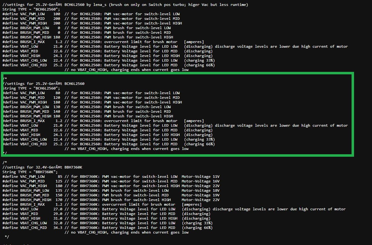
Konfigurationsdatei für PWM- und Batteriespannungswerte
HIGH #define BRUSH_PWM_LOW 0 // for BCHL2560: BRUSH for switch-level LOW #define BRUSH_PWM_MID 130 // for BCHL2560: BRUSH for switch-level MID #define BRUSH_PWM_HIGH 130 // for BCHL2560: BRUSH for switch-level
in „Bosch Athlet 25,2 V Akku 7 Stück Tauschen“ · Analoge Elektronik und Schaltungstechnik · · Screenshots
-
Datei
main_laeuft_14032021.c
the TMR2 to PR2 match interrupt IPR1bits.TMR1IP = 1; //TMR1 Overflow Interrupt Priority bit //1 = High priority //0 = Low priority IPR1bits.TMR2IP = 1; //TMR2 Overflow Interrupt Priority bit //1 = High priority //0 = Low priority //Timer2 Einstellungen //----------------------------------------------
in „C18_PIC18Fx_Code läuft nicht“ · Mikrocontroller und Digitale Elektronik ·
-
PDF
32mb_asyncpage_cr1_0_p24z.pdf
page 20. The Low-Z timings measure a 100mV transition away from the High-Z (V CCQ/2) level toward either VOH or VOL. 2. Low-Z to High-Z timings are tested with the circuit shown in Figure 15 on page 20. The High-Z timings
in „vfbga layout ohne durchkontaktierung möglich?“ · Platinen ·
-
PDF
8051.pdf
EPROM Only); V SS 0V) Symbol Parameter Min Typ(1) Max Unit Test (87C51/80C51BH) Conditions V Input Low Voltage (Except EA) b 0.5 0.2 V b 0.25 V IL CC VIL1 Input Low Voltage to EA 0 0.2 CCb 0.45 V VIH Input High Voltage (Except XTAL1, RST) 0CCV 1.0 VCCa 0.5 V a a VIH1 Input High Voltage (XTAL1, RST) 0.7
in „Mikrocontrollerboard: Funktioniert das?“ · Mikrocontroller und Digitale Elektronik ·
-
PDF
Datenblatt_Pegelwandler_TXS0108E.pdf
5.5 1.7 4.5 (high-to-low output) Open-drain driving ns Propagation Push-pull driving 3.8 4.3 tPLH delay time A-to-B 112 449 86 339 (low-to-high output) Open-drain driving ten Enable time OE-to-A or B Push-pull driving
in „Wozu Pull-Down Widerstand?“ · Mikrocontroller und Digitale Elektronik ·
-
Datei
prog.asm
|dd(dd)| | 4 | command5: cpi data, 'R' brne command6 ldi data, 0x28 ; read high byte rcall transfer ; #1 mov data, highAddress rcall transfer ; #2 mov data, lowAddress rcall transfer ; #3 ldi data, 0x00 rcall transfer ; #4 rcall transmit ldi data, 0x20 ; read low byte rcall transfer ; #1 mov data, highAddress rcall transfer ; #2 mov data, lowAddress rcall transfer ; #3 ldi data, 0x00 rcall transfer ; #4 rcall transmit ; autoincrement address ldi temp1, 1 clr temp2 add lowAddress, temp1 adc highAddress
-
Datei
T6963.c
Display's l schen void lcd_status(void) { DATA_DIR_IN(); // Port A als Eingang LCD_CD_H(); // Commando High LCD_RD_L(); // Read Low LCD_CE_L(); // Chip Enable Low LCD_STATUS = LCD_READ; // Status lesen LCD_CE_H(); // Chip Enable High LCD_RD_H(); // Read High LCD_STATUS &= (0x03); // Bits ausmaskieren } void lcd_status_am(void) { DATA_DIR_IN(); // Port 2 als Eingang LCD_CD_H(); // Commando High LCD_RD_L(); // Read Low LCD_CE_L(); // Chip Enable Low LCD_STATUS = LCD_READ; // Status lesen LCD_CE_H(); // Chip Enable High LCD_RD_H(); // Read High LCD_STATUS &= (0x08); // Bits ausmaskieren } void
-
Datei
1wire.s
DS_PIN,DS18b20 ;Wenn Pin High Fehler rjmp DS_error2 rjmp DS_ok ret DS_error: rcall lcd_clear ; Display löschen ldi ZL, LOW(error*2) ; Adresse des Strings in den ldi ZH, HIGH(error*2) ; Z-Pointer laden rcall lcd_flash_string ; Unterprogramm
in „ds18s20 atmega16 asm“ · Mikrocontroller und Digitale Elektronik ·
-
Datei
g_lcd.c
delay(clock=20000000) int status,st_ex, st_drw, st_adr, st_adw, rdata, wdata,i; reset() { output_high(pin_d4); delay_ms(1); output_low(pin_d4); } int check_status() { int status; output_high(pin_d3); //CD output_low(pin_d1); //RD output_high(pin_d0); //WR output_low(pin_d2); //CE delay_us(10); status
in „T6963 mit PIC16F877 und CCS“ · Mikrocontroller und Digitale Elektronik ·
-
PDF
Si_4420.pdf
Programmable in 0.1 V steps 2.25 5.35 V V lba Low battery detection accuracy +/-3 % V il Digital input low level voltage 0.3*V dd V V ih Digital input high level voltage 0.7*Vdd V I Digital input current V = 0 V -1 1 µA il il Iih Digital input current
-
Datei
LCD_Minimal.c
LCD_DATA_OUT DDRA = 0xFF /********************************************/ void LCD_WR_Trigger() { LCD_WR_LOW; _delay_us(5); LCD_WR_HIGH; } /********************************************/ void LCD_WriteCMD (uint8_t value) { LCD_RS_LOW; /* DC low: command DC high: data */ LCD_CS_LOW; LCD_DATA_PORT = value; LCD_WR_Trigger(); LCD_CS_HIGH; } /********************************************/ void LCD_WriteData (uint8_t value) { LCD_RS_HIGH; /* DC low: command DC high: data */ LCD_CS_LOW; LCD_DATA_PORT = value; LCD_WR_Trigger(); LCD_CS_HIGH
in „LCD mit ILI9325 funktioniert nicht!“ · Mikrocontroller und Digitale Elektronik ·
-
Datei
LCDprint.inc
'0' ;Ziffer für Tausender, Zahl ist jetzt negativ dec wl ;Tausender Stelle verkleinern und subi xl,low(-10000) ;1 Mio zur (negativen) Zahl addieren, sbci xh,high(-10000) ;bis Zahl wieder positiv wird sbci yl,byte3(-10000) ; brcs pc-4 ;noch negativ? ja... subi xl,low(10000) ;nein, 10000 von der (positiven
in „Konvertierung nach ASCII“ · Mikrocontroller und Digitale Elektronik ·
-
Datei
LCDprint.inc
'0' ;Ziffer für Tausender, Zahl ist jetzt negativ dec wl ;Tausender Stelle verkleinern und subi xl,low(-10000) ;1 Mio zur (negativen) Zahl addieren, sbci xh,high(-10000) ;bis Zahl wieder positiv wird sbci yl,byte3(-10000) ; brcs pc-4 ;noch negativ? ja... subi xl,low(10000) ;nein, 10000 von der (positiven
in „AD-Wandler - Fließkomma-Umwandlung“ · Mikrocontroller und Digitale Elektronik ·
-
PDF
AND9674-D.PDF
and power to the high−side gate drive circuitry of the ground−referenced low−side circuits. The high−voltage high−voltage gate−drive IC is the bootstrap power supply. gate−drive ICs are differentiated by unique level−shift
in „Bootstrap Kondensator richtig wählen“ · Analoge Elektronik und Schaltungstechnik ·
-
PDF
AD-PCB-Chapter4_Print_A.pdf
Applications Type Typical DA Advantages Disadvantages NPO Ceramics < 0.1% Small case size DA generally low Inexpensive (may not be Many vendors specified) Good stability Low maximum Low inductance value >0.2% Low inductance Poor stability Monolithic Ceramic (High K) Wide range of Poor DA values High voltage
in „ADCs: Digitale Masse und Oszillator an Analogmasse?“ · Analoge Elektronik und Schaltungstechnik ·
-
Datei
TST0_1_3.ASM
Reqeust 2 reti ; Timer/Counter 0 Compare Match reti ; Store Programm Memory Ready Reset_MC: ldi Temp0, Low(RAMEND) ; Load Low Ramend in Temp0 out SPL, Temp0 ; Set Low Stack Pointer with Temp0 ldi Temp0, High(RAMEND) ; Load High Ramend in Temp0 out SPH, Temp0 ; Set High Stack Pointer with Temp0 ser Temp0
in „ATMega8535 als Display Ansteuerung“ · Mikrocontroller und Digitale Elektronik ·
-
Datei
HEX_ASC_16.asm
: inc temp subi temp1, low (10000) sbci temp2, HIGH (10000) brcc FUNKTION_HEX_ASC_10000 dec temp subi temp, -48 ; HEX->ASC push temp ; temp auf dem Stack sichern subi temp1, low (-10000) sbci temp2, HIGH (-10000) clr temp FUNKTION_HEX_ASC
in „HEX-ASC Wandlung 16 Bit (Assembler) nur 5 Register“ · Projekte & Code ·
-
PDF
U2270B_.pdf
. Equivalent Circuit of Pin CFE 30 µA CFE 9 4684E–RFID–02/08 3.8 Function Table CFE MS COIL1 COIL2 Low Low High High Low High Low High High Low High High OE Output STANDBY U2270B Low Enabled Low Standby mode High Disabled High Active 4. Applications To achieve the system performance, consider the power-supply
in „Verzweiflung am U2270B“ · Mikrocontroller und Digitale Elektronik ·
-
PDF
KS0093.pdf
" IF = "Low" or "High": serial interface mode IF I When PS = High IF = "Low": 4-bit bus mode IF = "High": 8-bit bus mode SEG direction selection input When DIRS = "Low” DIRS I SEG1 → SEG2 → SEG79 → SEG80 When DIRS
in „LCD seriell ansteuern ST7093/KS0093“ · Mikrocontroller und Digitale Elektronik ·
-
Datei
tsv99x_series.txt
{IF(V(val_vdep_source)>=0, 0, V(val_vdep_source))} EVLIM_HIGH_VOUT NET0375 0 VCCP 0 1.0 R_ICCSAT_HIGH ICC_OUT_HIGH 0 1K R_ICCSAT_LOW ICC_OUT_LOW 0 1K RPROT_IN_P_VCCP NET0123 VCCP 15K RPROT_IN_M_VCCP VCCP NET0190 15K RD1 VCCP_ENHANCED VO_DIFF_PLUS {RD} RD2 VCCP_ENHANCED
in „Simulation LTSpice läuft extrem langsam (Filtersimulation OP Amp)“ · Analoge Elektronik und Schaltungstechnik ·
-
PDF
u2270b.pdf
Semiconductors Rev.A3, 13-Dec-96 U2270B Function Table CFE MS COIL1 COIL2 ÁÁÁÁÁÁÁÁÁÁÁÁÁÁÁÁÁÁÁÁÁÁÁÁÁÁÁÁÁÁÁÁ Low Low High High ÁÁÁÁÁÁÁÁÁÁÁÁÁÁÁÁÁÁÁÁÁÁÁÁÁÁÁÁÁÁÁÁ Low High Low High ÁÁÁÁÁÁÁÁÁÁÁÁÁHighÁÁÁÁÁÁÁÁÁÁÁÁÁÁÁ Low Á ÁÁÁÁÁÁÁÁÁÁÁÁÁÁÁ Á Á ÁÁÁÁÁÁÁÁÁÁÁÁÁÁÁ ÁÁÁÁÁÁÁÁÁ High ÁÁÁÁÁÁÁÁ High Á ÁÁÁÁÁÁÁÁÁÁÁÁÁÁÁ Á Á ÁÁÁÁÁÁÁÁÁÁÁÁÁÁÁ
in „Pollin RFID Entwicklungsboard“ · Mikrocontroller und Digitale Elektronik ·
-
PDF
ks0073.pdf
enable bit BE = “High”, makes user font of CGRAM and segment of SEGRAMblinking. The quantity of blink is assigned the highest 2 bit of CGRAM/SEGRAM. LP: Low power consumption mode enable bit When EXT port input is “Low”
in „RE bit beim KS0073“ · Mikrocontroller und Digitale Elektronik ·
-
PDF
ks0073.pdf
enable bit BE = “High”, makes user font of CGRAM and segment of SEGRAMblinking. The quantity of blink is assigned the highest 2 bit of CGRAM/SEGRAM. LP: Low power consumption mode enable bit When EXT port input is “Low”
in „EA DIP204-4 Datenblatt verständnis“ · Mikrocontroller und Digitale Elektronik ·
-
PDF
ks0073.pdf
enable bit BE = “High”, makes user font of CGRAM and segment of SEGRAMblinking. The quantity of blink is assigned the highest 2 bit of CGRAM/SEGRAM. LP: Low power consumption mode enable bit When EXT port input is “Low”
in „LCD Display DIP204-6“ · Mikrocontroller und Digitale Elektronik ·
-
PDF
ks0073.pdf
enable bit BE = “High”, makes user font of CGRAM and segment of SEGRAMblinking. The quantity of blink is assigned the highest 2 bit of CGRAM/SEGRAM. LP: Low power consumption mode enable bit When EXT port input is “Low”
in „Initialisierung von KS0073“ · Mikrocontroller und Digitale Elektronik ·
-
PDF
Display_driver_ks0073.pdf
enable bit BE = “High”, makes user font of CGRAM and segment of SEGRAMblinking. The quantity of blink is assigned the highest 2 bit of CGRAM/SEGRAM. LP: Low power consumption mode enable bit When EXT port input is “Low”
in „LCD Display ansteuern mit KS0073“ · Mikrocontroller und Digitale Elektronik ·
-
PDF
ks0073.pdf
enable bit BE = “High”, makes user font of CGRAM and segment of SEGRAMblinking. The quantity of blink is assigned the highest 2 bit of CGRAM/SEGRAM. LP: Low power consumption mode enable bit When EXT port input is “Low”
in „Probleme mit LCD“ · Mikrocontroller und Digitale Elektronik ·
-
PDF
hd6402.pdf
receiver buffer other lengths. register. 37 I CLS2 These inputs program the CHARACTER 16 I SFD A high level on STATUS FLAGS DISABLE forces LENGTH SELECTED (CLS1 low CLS2 low 5 bits) the outputs PE, FE, OE, DR, TBRE to a high im- (CLS1 high CLS2 low 6 bits) (CLS1 low CLS2 pedance state. high 7 bits) (CLS1 high CLS2 high 8 bits.) 17 I RRC The Receiver register clock is 16X the receiver 38 I CLS1 See Pin 37-CLS2. data rate. 39 I EPE When PI is low, a high level on EVEN PARITY 18 I DRR A low level on DATA RECEIVED
in „IC gesucht: RS-232 eingehendes Byte an 8 Ports“ · Mikrocontroller und Digitale Elektronik ·
-
Datei
push_mathe.inc
eingebunden ***" cpushdiv_32_16: push zl ;Zeiger zur Stack-Manipulation push zh push r16 ;Divosor low push r17 ;Divisor high push r18 ;Divident low push r19 ;Divident l-high push r20 ;Divident h-low push r21 ;Divident high push r22 ;Temp-Divisor low push r23 ;Temp-Divisor high push r24 ;Schleifenzähler
in „ATtiny45 - Timer 'Problem' - Assembler“ · Mikrocontroller und Digitale Elektronik ·
-
PDF
h-bridge-driver_hip4081a.pdf
input overrides BHI high level input. The pin can be driven by signal levels of 0V to 15V (no great). than V DD 3 DIS DISable input. Logic level input that when taken high sets all four outputs low. DIS high overrides all other
in „Motorsteuerung AVR Atmega per ISP flashen“ · Mikrocontroller und Digitale Elektronik ·
-
PDF
LYT4321E.pdf
LYT4211-4218/4311-4318 Topology Isolation Efficiency Cost THD Output Voltage Isolated Flyback Yes 88% High Best Any Buck No 92% Low Good Limited Tapped-Buck No 89% Middle Best Any Buck-Boost No 90% Low Best High-Voltage Table 2. Performance of Different Topologies in a Typical Non-Dimmable 10 W Low-Line
in „PI LYTSwitch, wofuer diese Diode“ · Analoge Elektronik und Schaltungstechnik ·
-
PDF
MAX3816A.pdf
positive level allowed 15 V if logic level is 0 and no other side % of HOLD Supply driver is asserting low on the Display 20 same node (series mode) side Threshold used to detect high-to-low % of High-to-Low Threshold V TRIGIH transition relative to supplCC(for cable 75 side, DD for display side) Supply Threshold used to detect low-to- Cable high transition relative to supplyide 12.5 % of Low-to-High Threshold VTRIGIL (VCC for cable side,DD for Display 17.5 Supply display side) side Output-High-State Current Limit Output in ramp-up
in „[S] Extender für HDMI über CAT5e (1080p@60Hz)“ · Markt ·
-
PDF
AD2500_Macro_Assembler_V402_Manual_Linker.pdf
follows: High digit of high byte of address Low digit of high byte of address High digit of mid byte of address Low digit of mid byte of address High digit of low byte of address Low digit of low byte of address
in „2500 A.D. Z80 Macro Assembler“ · Mikrocontroller und Digitale Elektronik ·
-
Datei
644-1.asm
; Cursor auf Stelle 1, Zeile 2 call lcd_command ldi ZL, LOW(Text02*2) ; Adresse des Strings in den ldi ZH, HIGH(Text02*2) ; Z-Pointer laden rcall lcd_flash_string jmp Menuer Seite_1: ldi ZL, LOW(Text11*2) ; Adresse des Strings in den ldi ZH, HIGH(Text11*2) ;
in „komisches Verhalten STK500 / atmega644P / 2x20Display“ · Mikrocontroller und Digitale Elektronik ·
-
Datei
main.c
2: if (Time_flag == 0) { tmp2 = Set_2_low; // User Low setting } else { tmp2 = Set_2_high; // User High setting } break; } if (Time_flag) { SYNC_OUT_ON } else { SYNC_OUT_OFF } OCR1B = tmp1 / 2; OCR1A = tmp2 / 2; // init LCD once per second,
in „Hilfe bei Arduino OLED I2C Menü“ · Mikrocontroller und Digitale Elektronik ·
-
Datei
main.c
(uint8_t paramter){ uint8_t i; PORTB &= ~(1<<DDB2); //turn CS low PORTC |= (1<<DDC0); //turn A0 high for(i = 0; i < 8; i++){ if(paramter & 128){ PORTB |= (1<<DDB3); //turn SDA high } else { PORTB &= ~(1<<DDB3); //turn SDA low } PORTB |= (1<<DDB5); //turn SCK high
in „TFT_ILI9163C mit Arduino richtig verbinden“ · Mikrocontroller und Digitale Elektronik ·
-
Datei
k2p11.asm
dunkel schalten ; ;Verkettete Liste Anfangswerte Zähler und Zeiger laden ; _loop: ldi xl,LOW (liste) ;X <- laufender Zeiger... ldi xh,HIGH(liste) ;...auf Listenelemente sts HIGH(kopfz+1),xh ;Kopfzeiger_High laden... sts LOW (kopfz),xl ;...Kopfzeiger_Low mit Anfangsadresse ; ; Verkettete Liste
in „Buch AVR von Günter Schmitt durcharbeiten“ · Mikrocontroller und Digitale Elektronik ·
-
PDF
irs2453d.pdf
Oscillator timing capacitor input 4 RT Oscillator timing resistor input 5 SD Shutdown input 6 LO1 Low side gate driver output 7 LO2 Low side gate driver output 8 VS2 High voltage floating supply return 9 HO2 High side gate driver output 10 VB2 High side gate driver floating supply 11 NC No connect 12
in „oscillator, 555, gate driver“ · Mikrocontroller und Digitale Elektronik ·
-
PDF
EKG_usw_Informationformedicalapplications_von_TI.pdf
1.55 OPA241 Very low power, high precision I S, D, Q 0.25 0.4 20 nA 45 0.035 0.01 2.7 to 36 0.03 1.06 OPA251 microPower, high CMRR I S, D, Q 0.25 0.4 2 nA 45 0.35 0.1 2.7 to 36 0.025 1.07 OPA244 microPower, SS, low cost
in „EKG Schaltung Neuling“ · Analoge Elektronik und Schaltungstechnik ·
-
Datei
GB_Geschenk_Abgespeckt_2sensoren.ino
(TP3B, LOW); delayMicroseconds(5); pinMode(TP1A,OUTPUT); digitalWrite(TP1A, HIGH); pinMode(TP2A,OUTPUT); digitalWrite(TP2A, HIGH); pinMode(TP3A,OUTPUT); digitalWrite(TP3A, HIGH); delayMicroseconds(5); pinMode(
in „ADC mit ATmega8A“ · Mikrocontroller und Digitale Elektronik ·
-
Datei
lm75_anzeige.h
Ansprechen des LM75 i2c_write(0); // Die "0" für lesen senden i2c_start(); i2c_write(++i2c_addr); higher_byte=i2c_read(1); // Empfang des higher_byte vom Temperatur-Register lower_byte=i2c_read(0); // Empfang des lower_byte vom Temperatur-Register i2c_stop(); // Ende zur Datenübertragung auf dem I2C-Bus
-
Datei
lm75_anzeige.h
Ansprechen des LM75 i2c_write(0); // Die "0" für lesen senden i2c_start(); i2c_write(++i2c_addr); higher_byte=i2c_read(1); // Empfang des higher_byte vom Temperatur-Register lower_byte=i2c_read(0); // Empfang des lower_byte vom Temperatur-Register i2c_stop(); // Ende zur Datenübertragung auf dem I2C-Bus