-
Datei
main.lst
\ VICVectAddr14: \ 00000000 DS8 4 \ In segment DATA_AN, at 0xfffff13c \ unsigned long volatile __data VICVectAddr15 \ VICVectAddr15: \ 00000000 DS8 4 \ In segment DATA_AN, at 0xfffff200 \ union <unnamed> volatile __
in „LPC2103 Speicherproblem“ · Mikrocontroller und Digitale Elektronik ·
-
Datei
ds1307.c
//RTC starten int sec; if (ds1307_started) return; sec = (read_ds1307(0) & (~0x80)); //CH = 0 -> start. write_ds1307(0,sec); ds1307_started = 1; } void stop_ds1307(){ //RTC stoppen int sec; sec = (read_ds1307(0) | 0x80); //CH = 1
in „DS1307 verhält sich komisch“ · Mikrocontroller und Digitale Elektronik ·
-
PDF
Infineon-IRFHS8342-DataSheet-v01_01-EN.pdf
IRFHS8342PbF HEXFET Power MOSFET V 30 V TOP VIEW DS V GS max ± 20 V D R DS(on) max D 1 6 D D 16.0 mΩ D G (@V GS = 10V) D 2 D 5 D Q g(typical) 4.2 nC D (@V = 4.5V) D S GS G 3 S 4 S S I D 8.5 d A 2mm x 2mm PQFN (@T c(Bottom) 25°C) Applications • Control
in „IC identifizieren“ · Analoge Elektronik und Schaltungstechnik ·
-
PDF
aod522.pdf
V 90 A D(n) DS GS VGS = 10 V,DI = 21.8 A 0.007 Drain-Source On-State Resistance RDS(on) VGS = 4.5 V,DI = 18A 0.009 a Forward Transconductance gfs V DS = 15 V,DI = 21.8 A 160 S b Dynam i Input Capacita ce Ciss 2201
in „Suche einfache Möglichkeit 24V 6A DC zu schalten“ · Analoge Elektronik und Schaltungstechnik ·
-
PDF
AN1325_Metall_Over_Cap.pdf
Application Maestro, CodeGuard, devices in life support and/or safety applications is entirely at dsPICDEM, dsPICDEM.net, dsPICworks, dsSPEAK, ECAN, the buyer’s risk, and the buyer agrees to defend, indemnify and ECONOMONITOR, FanSense, HI-TIDE, In-Circuit Serial hold harmless Microchip from any and
in „Tastenverriegelung (Tastensperre)“ · Mikrocontroller und Digitale Elektronik ·
-
PDF
bs1Appnotes.pdf
in °C or °F, as shown in the listing. Page 190 •BASICStampProgrammingManual1.9•Parallax,Inc. 23: DS1620 Digital Thermometer BASIC Stamp I Application Notes OnceyouhaveconfiguredtheDS1620,youdon’thavetoreconfigureit unlessyouwanttochangeasetting.TheDS1620storesitsconfiguration in EEPROM (electrically
in „Smartcard-Kode-Schloss mit PIC16F84“ · Mikrocontroller und Digitale Elektronik ·
-
PDF
dm45.pdf
gold) G 2 DQ1 20 DQ5 38 DQ36 56 DQ31 72-pin SIMM low profile (1.00") DM 3 DQ19 21 DQ23 39 Vss 57 DQ14 4 DQ2 22 DQ6 40 CAS0# 58 DQ32 72-pin SIMM (gold) low profile (1.00") DG 5 DQ20 23 DQ24 41 CAS2# 59 Vcc 6 DQ3 24 DQ7 42 CAS3# 60 DQ33 KEY TIMING PARAMETERS 7 DQ21 25 DQ25 43 CAS1# 61 DQ15 8 DQ4 26 DQ8
-
PDF
schiebereg.pdf
shift register clock input ST 12 storage register clock input CP OE 13 output enable (active LOW) DS 14 serial data input VCC 16 positive supply voltage handbook, halfpage 11 12 handbook, halfpage Q1 1 16 VCC SHCP STCP Q ' 9 Q2 2 15 Q0 7 Q0 15 Q3 3 14 DS 1 Q1 Q4 4 13 OE Q 2 595 2 Q5 5 12 STCP 14 D Q3
in „wie steuer ich nen sn7447 mit avr an??“ · Mikrocontroller und Digitale Elektronik ·
-
PDF
74HC_HCT595_CNV_3.pdf
shift register clock input ST 12 storage register clock input CP OE 13 output enable (active LOW) DS 14 serial data input VCC 16 positive supply voltage handbook, halfpage 11 12 handbook, halfpage Q1 1 16 VCC SHCP STCP Q ' 9 Q2 2 15 Q0 7 Q0 15 Q3 3 14 DS 1 Q1 Q4 4 13 OE Q 2 595 2 Q5 5 12 STCP 14 D Q3
in „LCD DEM20485 in gerade Zeile springen (c't-Bot)“ · Mikrocontroller und Digitale Elektronik ·
-
Datei
ds1820.h
(void) { bool bBit; DS1820_DisableInterrupts(); output_low(DS1820_DATAPIN); DS1820_DelayUs(DS1820_MSTR_BITSTART); input(DS1820_DATAPIN); DS1820_DelayUs(DS1820_BITREAD_DLY); bBit = input(DS1820_DATAPIN); DS1820_EnableInterrupts
-
Datei
ds1820.h
*************************************/ bool DS1820_ReadBit(void) { bool bBit; DS1820_DisableInterrupts(); output_low(DS1820_DATAPIN); DS1820_DelayUs(DS1820_MSTR_BITSTART); input(DS1820_DATAPIN); DS1820_DelayUs(DS1820_BITREAD_DLY); bBit = input(DS1820
in „ds18b20 temperaturmessung mit pic18f4550“ · Mikrocontroller und Digitale Elektronik ·
-
Datei
Compiler.h
// dsPIC33E processor #define COMPILER_MPLAB_C30 #include <p33Exxxx.h> #elif defined(__dsPIC30F__) && defined(__C30__) // Microchip C30 compiler // dsPIC30F processor #define COMPILER_MPLAB_C30 #include <p30fxxxx.h
in „Anfängerproblem PIC18“ · Mikrocontroller und Digitale Elektronik ·
-
PDF
Vishay-Silcnx_FET_VoltCntrlRES_AN105.pdf
Distortion vs. Temperature Without Feedback With Feedback Temperature (▯C) r = r r = 10 r r = r r = 10 r DS DS(on) DS DS(on) DS DS(on) DS DS(on) +125 >13% >6% <0.5% <0.5% +25 >10% >5% <0.5% <0.5% –55 3.9% 3.2% <0.5% <0.5% 4 Siliconix 10-Mar-97 AN105 Distortion resulting from changes in temperature is also
in „Spannungsgeregelter Widerstand“ · Analoge Elektronik und Schaltungstechnik ·
-
PDF
camaro_stand_alone.pdf
X6B S 3-2 +5V 1 L-Solenoid PC817 R7 4 4 R14 X11B X1C OK3 0 0 S 3 2 GND Ground X6C GND 4 4 JPINHD-1X1 PINHD-1X1 12V Ground G 6 1 7 1 JP9 X11A 7 0 X1D 220 Getriebe OUT 2 D D GND 1 2 IRF540 4 1 C C Getriebe OUT D3 D Q2 BSOL3 21 V V 14 1N4004 PC817
in „Stn1110 am atmega2560 uart probleme“ · Mikrocontroller und Digitale Elektronik ·
-
PDF
technical.pdf
V Th)2 (11.166) gm = β · (1 + λDS )(VGS − VTh) (11.167) γ gmb= g m √ (11.168) 2 Φ − VBS • linear region:DS < VGS − VTh Id= β · (1 + λDS ) · GS − VTh − VDS /2) ·DS (11.169) gds= β · (1 + λDS ) · GS − VTh − VDS ) + β ·λDS · (GS − VTh −
-
PDF
miniboard.pdf
N N N N N N N A2 GND_D11 GND_Y19 G13 G G G G G G G GND_A2 GND_G13 B1 XCF08PFS48C Y2 GND_Y2 GND_B1 L14 A A B F F F6 H K14 GND_K14 GND_L14 G12 GND_G12 GND_Y1 Y1 J14 GND_J14 GND_W1 W1 Y20 V14 M14 GND_Y20 GND_V14 A20 GND_M14 GND_A20 L7 M7 GND_M7 GND_L7 H14 G18 GND_G18 GND_H14 2.5V 2.5V 2.5V 2.5V N7 GND_N7
in „Xinlinx Virtex-4 FX12 363 / Miniboard / Clock Pin“ · FPGA, VHDL & Co. ·
-
PDF
BST-BMP180-DS000-07.pdf
BMP180 Data sheet Document revision 2.3 Document release date 25 May 2011 Document number BST-BMP180-DS000-07 Technical reference code(s) 0 273 300 244 Notes Data in this document are subject to change without notice. Product photos and pictures are for illustration purposes only and may differ from the
in „Suche Projektpartner für Kalmanfilter-Implementierung“ · Digitale Signalverarbeitung / DSP / Machine Learning ·
-
PDF
TPIC6C595D_16pin.pdf
L 30 pF, CC(FRQ) Logic supply current at frequency All outputs off, See Figures 2 and 6 1.2 5 mA V DS(on)= 0.5 V, IN= ID, N Nominal current T C 85°C, See Notes 5, 6, and 7 90 mA V DS = 30 V, V CC = 5.5 V 0.1 0.2 I Off-state drain current µA DSX V DS = 30 V, V CC = 5.5 V, 0.15 0.3 T C 125°C I = 50 mA,
in „Seriell ansteuern TPIC6C595, wie geht das ?“ · Mikrocontroller und Digitale Elektronik ·
-
PDF
atmel-flash-speicher.pdf
I/O6 NC No Connect I/O1 14 19 I/O5 I/O2 15 18 I/O4 CMOS Flash VSOP Top View (8 x 14 mm) or GND 16 17 I/O3 TSOP Top View (8 x 20 mm) Memory Type 1 PLCC Top View A11 1 32 OE 2 5 C E A9 2 A10 A A N N V W N C 31 A8 3 30 CE 4 3 2 1
in „Speicher für Messwerte“ · Mikrocontroller und Digitale Elektronik ·
-
PDF
ALD110800-1489.pdf
whichclassifiesthemasbothenhancementmode GN1 2 15 GN2 and depletion mode devices. When the gate is set at 0.00V, the drain M1 M2 14 D current is +1µA@ V DS = 0.1V, which allows a class of circuits with output DN1 3 N2 S 4 V+ 13 V+ voltage level biased at or near input voltage level without voltage level 12 shift. These devices exhibit
in „Radiobasteln - Was hat 2018 noch Aussicht auf Erfolg ?“ · HF, Funk und Felder ·
-
PDF
1-BTS7810K_11-03-2003.pdf
H – 26 35 mΩ ISH = 5 A on-resistance of highside T j= 25 °C switch Static drain-source RDS ON L – 14 17 mΩ ISL= 5 A; on-resistance of lowside V IL= 5 V switch T = 25 °C j Static path on-resistance RDS ON – – 100 mΩ R DS ON H R DS ON L ISH = 5 A; Short Circuit of highside switch to GND Initial peak SC
in „Kuehlkoerper“ · Mikrocontroller und Digitale Elektronik ·
-
PDF
BTS7810K_11-03-2003.pdf
H – 26 35 mΩ ISH = 5 A on-resistance of highside T j= 25 °C switch Static drain-source RDS ON L – 14 17 mΩ ISL= 5 A; on-resistance of lowside V IL= 5 V switch T = 25 °C j Static path on-resistance RDS ON – – 100 mΩ R DS ON H R DS ON L ISH = 5 A; Short Circuit of highside switch to GND Initial peak SC
in „Ansteuerung eines Magnetventils --> Frage zu Datenblatt“ · Analoge Elektronik und Schaltungstechnik ·
-
PDF
488161_1_.pdf
300 / 12,0 • 11,0 / 2000 1000 23,0 / 4500 100 300 / 12,0 • 13,0 / 2000 1000 26,0 / 4500 100 300 / 14,0 • 7,5 / 2000 1000 26,0 / 4500 100 300 / 14,0 • 10,0 / 2000 1000 26,0 / 4500 100 300 / 14,0 • 12,0 / 2000 1000 26,0 / 4500 100 300 / 14,0 • 14,0 / 2000 Diamantfeilen Spezialfeilen, mit dem härtesten
in „Funktionsweise von analogen elektronischen Drehzahlmessern?“ · Analoge Elektronik und Schaltungstechnik ·
-
PDF
MSP430F5438IPZ.pdf
Channel B: ADC12_A I/O Package (KB) (KB) UART/IrDA/ SPI/I C (Ch) Type SPI MSP430F5438 256 16 5, 3 7 4 4 14 ext / 2 int 87 100 PZ MSP430F5437 256 16 5, 3 7 2 2 14 ext / 2 int 67 80 PN MSP430F5436 192 16 5, 3 7 4 4 14 ext / 2 int 87 100 PZ MSP430F5435 192 16 5, 3 7 2 2 14 ext / 2 int 67 80 PN MSP430F5419 128
in „Strombelastbarkeit MSP430“ · Mikrocontroller und Digitale Elektronik ·
-
Datei
catneu2.asm
ph_lampe ds 16 ;Phasenanschnittswerte (Word) lampe ds 8 ;Empfangene Lampen-Kanal-Bytes (0..255) softstart ds 1 ;255 normal, nach Einschalten von 0 auf 255 l_softstart ds 1 ;Low-Byte von Softstart overheat ds 1 ;
in „DMX-Receiver“ · Mikrocontroller und Digitale Elektronik ·
-
PDF
DS1210.pdf
consumption. The 8-pin DIP package keeps PC board real estate requirements to a minimum. By combining the DS1210 Nonvolatile Controller Chip with a CMOS memory and batteries, nonvolatile RAM operation can be achieved. 1 of 6 111899 DS1210 OPERATION The DS1210 nonvolatile controller performs five circuit functions
in „Suche Chip aus Mega-Drive-2-Spielplatine“ · Mikrocontroller und Digitale Elektronik ·
-
PDF
DS1210.pdf
consumption. The 8-pin DIP package keeps PC board real estate requirements to a minimum. By combining the DS1210 Nonvolatile Controller Chip with a CMOS memory and batteries, nonvolatile RAM operation can be achieved. 1 of 6 111899 DS1210 OPERATION The DS1210 nonvolatile controller performs five circuit functions
in „DS1210 als Ersatz für BA6162?“ · Mikrocontroller und Digitale Elektronik ·
-
PDF
68332_test.pdf
A10 D12 119 D12 A12 52 A12 A12 25 A11 A12 25 A11 D13 118 D13 A13 56 A13 A13 4 A12 A13 4 A12 D14 117 57 A14 A14 28 A14 28 D15 116 D14 A14 58 A15 A15 3 A13 A15 3 A13 D15 A15 60 A16 A16 31 A14 A16 31 A14 CS2 140 A16 63 A17 A17 2 A15 A17 2 A15 CSBOOT A17 A18 A18 A16 A18 A16 141 BR/CS0 A18 64 A19 A19
in „Motorola MC68332 und BD32“ · Mikrocontroller und Digitale Elektronik ·
-
Datei
BAUD.ass
auf binaer einsparen bset STOP,#1 xmal 12 bit adresszaehler durchlaufen bset TAKT,#$B0 adressbyte ds1077 bset TAKT+1,#$02 commandmux ds1077 bset TAKT+2,#$1F muxmsb ds1077 bset TAKT+3,#$00 muxlsb ds1077 bset TAKT+4,#$B0 adressbyte ds1077 bset TAKT+5,#$01 commanddiv ds1077 bset TAKT+6,#$00 divmsb ds1077
-
PDF
irlml6401.pdf
On-Resistance Vs. Temperature www.irf.com 3 IRLML6401 1200 10 I = VGS = 0V, f = 1 MHZ D -4.3A Ciss = gs+ Cgd C ds SHORTED ) V DS =-10V 1000 C = C ( rss gd e 8 Coss = Cds Cgd a F Ciss o ( 800 V c e 6 n r i 600 o a - a t 4 C t C 400 a Coss , Crss S 200 G 2 - 0 0 1 10 100 0 4 8 12 16 V , Drain-to-Source Voltage (V) Q G Total Gate Charge (nC) DS Fig 5. Typical Capacitance Vs. Fig 6. Typical Gate Charge Vs. Drain-to-Source Voltage Gate-to-Source Voltage 100 1000 OPERATION IN THIS AREA LIMITED BY R DS(on) A t e )100 r ( u 10 n n TJ= 150 C e 10us
in „CMOS Transistoren“ · Mikrocontroller und Digitale Elektronik ·
-
PDF
IRLML6401.pdf
On-Resistance Vs. Temperature www.irf.com 3 IRLML6401 1200 10 I = VGS = 0V, f = 1 MHZ D -4.3A Ciss = gs+ Cgd C ds SHORTED ) V DS =-10V 1000 C = C ( rss gd e 8 Coss = Cds Cgd a F Ciss o ( 800 V c e 6 n r i 600 o a - a t 4 C t C 400 a Coss , Crss S 200 G 2 - 0 0 1 10 100 0 4 8 12 16 V , Drain-to-Source Voltage (V) Q G Total Gate Charge (nC) DS Fig 5. Typical Capacitance Vs. Fig 6. Typical Gate Charge Vs. Drain-to-Source Voltage Gate-to-Source Voltage 100 1000 OPERATION IN THIS AREA LIMITED BY R DS(on) A t e )100 r ( u 10 n n TJ= 150 C e 10us
in „parasitäres Glimmen beim LED-Muxing. Transistoren? Einstreuungen?“ · Mikrocontroller und Digitale Elektronik ·
-
PDF
IRLML6401.pdf
On-Resistance Vs. Temperature www.irf.com 3 IRLML6401 1200 10 I = VGS = 0V, f = 1 MHZ D -4.3A Ciss = gs+ Cgd C ds SHORTED ) V DS =-10V 1000 C = C ( rss gd e 8 Coss = Cds Cgd a F Ciss o ( 800 V c e 6 n r i 600 o a - a t 4 C t C 400 a Coss , Crss S 200 G 2 - 0 0 1 10 100 0 4 8 12 16 V , Drain-to-Source Voltage (V) Q G Total Gate Charge (nC) DS Fig 5. Typical Capacitance Vs. Fig 6. Typical Gate Charge Vs. Drain-to-Source Voltage Gate-to-Source Voltage 100 1000 OPERATION IN THIS AREA LIMITED BY R DS(on) A t e )100 r ( u 10 n n TJ= 150 C e 10us
in „LED Multiplexer glimmt“ · Mikrocontroller und Digitale Elektronik ·
-
PDF
LM3914.pdf
Voltage DS007970-22 DS007970-23 DS007970-24 Input Current Beyond LED Current vs LED Driver Current Signal Range (Pin 5) Reference Loading Regulation DS007970-25 DS007970-26 DS007970-27 Total Divider Resistance
in „Frage zu LM3914“ · Mikrocontroller und Digitale Elektronik ·
-
PDF
LM3914.pdf
Voltage DS007970-22 DS007970-23 DS007970-24 Input Current Beyond LED Current vs LED Driver Current Signal Range (Pin 5) Reference Loading Regulation DS007970-25 DS007970-26 DS007970-27 Total Divider Resistance
in „Drehzahlerfassung und Ausgabe“ · Mikrocontroller und Digitale Elektronik ·
-
PDF
LM3914.pdf
Voltage DS007970-22 DS007970-23 DS007970-24 Input Current Beyond LED Current vs LED Driver Current Signal Range (Pin 5) Reference Loading Regulation DS007970-25 DS007970-26 DS007970-27 Total Divider Resistance
in „LM 3914 Kaskade“ · Analoge Elektronik und Schaltungstechnik ·
-
PDF
LM3914.pdf
Voltage DS007970-22 DS007970-23 DS007970-24 Input Current Beyond LED Current vs LED Driver Current Signal Range (Pin 5) Reference Loading Regulation DS007970-25 DS007970-26 DS007970-27 Total Divider Resistance
in „LM3914 Display-Driver“ · Mikrocontroller und Digitale Elektronik ·
-
PDF
AON6500.pdf
Drain-Source Breakdown Voltage ID=250 A, V GSV 30 V V =30V, V =0V 1 IDSS Zero Gate Voltage Drain Current DS GS A T J55°C 5 IGSS Gate-Body leakage current V DS=0V, VGS ±20V 100 nA VGS(th) Gate Threshold Voltage V DS GS, D=250 A 1 1.4 2 V V =10V, I =20A 0.75 0.95 GS D m R DS(ON) Static Drain-Source On-Resistance
in „Unbekanntes Bauteil?“ · Analoge Elektronik und Schaltungstechnik ·
-
PDF
MCP3221.pdf
. 100 kHz. 2 4.13 I C Fast Mode Timing 2 I C specification where the frequency of SCL is 400 kHz. DS21732B-page 14 2003 Microchip Technology Inc. MCP3221 5.0 SERIAL COMMUNICATIONS Each data transfer is initiated with a START condition and terminated with a STOP condition. The number of 2 5.1 I C Bus
in „Suche Bauteilbezeichnung 5-Pin SOT-23 mit "S1SD" Marking“ · Mikrocontroller und Digitale Elektronik ·
-
PDF
mosfet_K3673.pdf
=0V 700 V Gate threshold voltage VGS(th) ID= 250 A VDS=V GS 3.0 5.0 V V DS=700V V GS=0V T c=25°C 25 µA Zero gate voltage drain current IDSS V DS=560V V GS=0V Tch=125°C 250 Gate-source leakage current IGSS V GS=±30V V DS=0V 100 nA Drain-source on-state resistance RDS(on) ID=
in „Mosfet K3673 01“ · Analoge Elektronik und Schaltungstechnik ·
-
PDF
ds18s20.pdf
COMMAND COMMAND COMMAND COMMAND COMMAND Y Y Y Y Y N DS18S20 TX MASTER T X FAMILY CODE BIT 0 ALARM 1 BYTE CONDITION ? Y DS18S20 TXBIT 0 DS18S20 X BIT 0 MASTER TXBIT 0 N N DS18S20 X BIT 0 BIT 0 SERIAL NUMBER MATCH? MATCH? 6 BYTES Y Y DS18S20 TX DS18S20 X BIT
in „Messabweichung beim 1-wire DS1“ · Mikrocontroller und Digitale Elektronik ·
-
PDF
datasheet_002.pdf
COMMAND COMMAND COMMAND COMMAND COMMAND Y Y Y Y Y N DS18S20 TX MASTER T X FAMILY CODE BIT 0 ALARM 1 BYTE CONDITION ? Y DS18S20 TXBIT 0 DS18S20 X BIT 0 MASTER TXBIT 0 N N DS18S20 X BIT 0 BIT 0 SERIAL NUMBER MATCH? MATCH? 6 BYTES Y Y DS18S20 TX DS18S20 X BIT
-
PDF
1.5KE6V8A.PDF
1.5KE15CA 12.80 14.30 15.80 1.0 5.0 21.2 71.0 0.084 1.5KE16A 1.5KE16CA 13.60 15.20 16.80 1.0 5.0 22.5 67.0 0.086 1.5KE18A 1.5KE18CA 15.30 17.10 18.90 1.0 5.0 25.2 59.5 0.088 1.5KE20A 1.5KE20CA 17.10 19.00 21.00 1.0 5.0
in „Welches Bauteil (Diode?) ist das?“ · Analoge Elektronik und Schaltungstechnik ·
-
PDF
DMOS_Analog_Switch_Introduction.pdf
SD5400 series comes in the This Application Note describes in detail the narrow body gull-wing SO-14 package. principle of operation of the SD210/5000 series of high-speed analog switches and switch arrays. It contains an explanation of the most Applications important switch characteristics, application
in „Gerät elektronisch abschalten“ · Mikrocontroller und Digitale Elektronik ·
-
 Bild
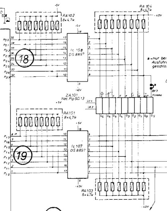
Ausschnitt eines Schaltplans
RA102 8x4,7k -5V P00 P01 P02 P03 P04 P05 P07 IC 108 DS 8897 19 18 17 16 15 14 13 12 11 10 9 8 7 6 5 2 1 0 ZA101 Nec. Fip 9D13 -5V RA101 8x4,7k -5V PG G5 G4 G3 G2 G1 G0 P17 P16 P15 P14 P13 P12 P11 P10 IC 107 DS 8897 18 17 16 15 14 13 12 11 10 9 8 7 6 5 2
in „VFD Segment leuchtet immer“ · Analoge Elektronik und Schaltungstechnik · · Schaltpläne
-
PDF
31029a.pdf
.............................................29-48 29 s S u t c o n 1997 Microchip Technology Inc. DS31029A page 29-1 PICmicro MID-RANGE MCU FAMILY 29.1 Introduction Each midrange instruction is a 14-bit word divided into an OPCODE which specifies the instruc- tion type and one or more operands which
in „PIC nach ändern von Code undefiniertes herumwüten des uC“ · Mikrocontroller und Digitale Elektronik ·
-
PDF
Wohnraumuhr2_Rev1.2.pdf
B21 9 f 74HC595N B6 R107 8 g B22 R123 8 g B7 R108 4 h u p B23 R124 4 h u p B8 R109 3 k B24 R125 3 k 14 15 B8 B9 R110 2 m g t r d B25 R126 2 m g t r d B SER QA R111 R127 B QB 1 B9 B10 R112 17 n B26 R128 17 n 11 SCK QC 2 B10 B11 R113 15 p B27 R129 15 p 10 SCL QD 3 B11 B12 14 r s B28 14 r s 4 B12 B13 R114 6 s B29 R130 6 s 12 QE 5 B13 B14 R115 7 t f e B30 R131 7 t f e RCK QF 6 B14 B15 R116 5u 12 B31 R132 5 u 12 QG 7 B15 DP DP QH 13 G QH* 9 74HC595N 14 15 B16 SER QA QB 1 B17 11 SCK QC 2 B18 C 10 SCL QD 3 B19 C QE 4 B20 12 5 B21 RCK QF
in „wohnraumuhr 2 - leiterplatte nach projekt scott huehn“ · Mikrocontroller und Digitale Elektronik ·
-
PDF
MCP73837.pdf
Current (I THERM ) FIGURE 2-18: Power Supply Ripple vs. Supply Voltage (V DD ). Rejection (PSRR). DS22071A-page 10 © 2007 Microchip Technology Inc. MCP73837/8 Note: Unless otherwise indicated, V DD = [VREG (typical) + 1V], OUT = 30 mA and T = A25°C, Constant-voltage mode. 16 0.1 1 0.1 14 A 0.9 OUT=
in „Verständnissfrage - MCP73837“ · Mikrocontroller und Digitale Elektronik ·
-
Datei
twi_lib.c
; twi1.Addr_SLA_Base = DS1631_BaseAdr; twi1.NrBytesToTransmit = 1; twi1.NrBytesToReceive = 0; twi1.TxRxBuffer[0] = DS1631_StartConvert; // &h51 TWI_TransmitReceive(); } // TWI_DS1631_StartConvertT // Reads Temperatur out of a
in „TWI MUX per SW an einem Port“ · Mikrocontroller und Digitale Elektronik ·
-
PDF
0704-015.pdf
current terminals to sensor pins*3 mm *Limits determined by separation of solder pad lands for leads. 14 ACS704ELC015-DS, Rev. 2 Worcester,Massachusetts01615-0036 (508)853-5000 www.allegromicro.com ACS704ELC-015 Chopper Stabilization Technique Chopper Stabilization is an innovative circuit technique that
in „Stromfluss detektor“ · Mikrocontroller und Digitale Elektronik ·
-
PDF
0704-015.pdf
current terminals to sensor pins*3 mm *Limits determined by separation of solder pad lands for leads. 14 ACS704ELC015-DS, Rev. 2 Worcester,Massachusetts01615-0036 (508)853-5000 www.allegromicro.com ACS704ELC-015 Chopper Stabilization Technique Chopper Stabilization is an innovative circuit technique that
in „Gibts eigentlich auch ADCs, die Strom messen?“ · Mikrocontroller und Digitale Elektronik ·