-
Datei
Testplatine.c
/* Testplatinenprogramm geschrieben von Mike Riedel Januar 2014 // Pinbelegung PIC 18F2420 RB7 RB6 RB5 RB4 RB3 RB2 RB1 RB0 VDD VSS RC7 RC6 RC5 RC4 | + ### ### ### ### ### ### ### ### ### ### ### ### ### ### + | | 28 27 26 25 24 23 22 21 20 19 18 17 16 15 | | +-+ | | | | | +-+ | |
in „Fehlerhafte Werte bei AD-Wandlung PIC18F2420“ · Mikrocontroller und Digitale Elektronik ·
-
Datei
I2C_test.asm
------------------------------------------------------------------------------------------- list p=16f887 ; festlegen welcher PIC #include <p16f887.inc> ; einbinden der .INClude - Datei ; Config-Word 1 & 2: __CONFIG _CONFIG1, _LVP_OFF & _FCMEN_OFF & _IESO_OFF & _BOR_OFF & _CPD_OFF & _CP_OFF & _MCLRE_ON
in „I2C und PIC16F887“ · Mikrocontroller und Digitale Elektronik ·
-
Datei
main.c
***************/ /* i.e. uint8_t <variable_name>; */ //PROGRAMM FOR BLINKING LED // // PROCESSOR : PIC16F877A #include <pic.h> #pragma config FOSC = INTRC_NOCLKOUT// Oscillator Selection bits (INTOSCIO oscillator: I/O function on RA6/OSC2/CLKOUT pin, I/O function on RA7/OSC1/CLKIN) #pragma config WDTE
in „PIC Anfängerproblem“ · Mikrocontroller und Digitale Elektronik ·
-
PDF
elektronische_Bauelemente.pdf
10 Power Switch ITS436L2 150 Leistungs-Multiplexer BTS432E2 28 quad-inverting power-driver HIP0081AS1 37 EPROM HN27512G-25 13 MCM27A08L 4 27C010L-15L 7 AM2732DC 3 D2732D 3 EPROM TMS-2708JL-35 8 EPROM MM2708Q 2 EPROM D27084C642 4 EPROM MCM2708C 1 EPROM NM27C512Q 4 EPROM M27C256B-12F1 1 EPROM M27512F1
-
Datei
Test_8.asm
; ;--Testprogramm : Automatisch bzw Tastendes hochzählen eines 7 Segment Displays------ ; list p=16F627 include "P16F627.inc" __CONFIG _BODEN_ON & _CP_OFF & _DATA_CP_OFF & _PWRTE_ON & _WDT_OFF & _LVP_OFF & _MCLRE_ON & _XT_OSC ;----------------------Variablen Benennung------------------------- TIMER0
in „PIC 16F627 ; 7Segment Ansteuerung“ · Mikrocontroller und Digitale Elektronik ·
-
 Bild
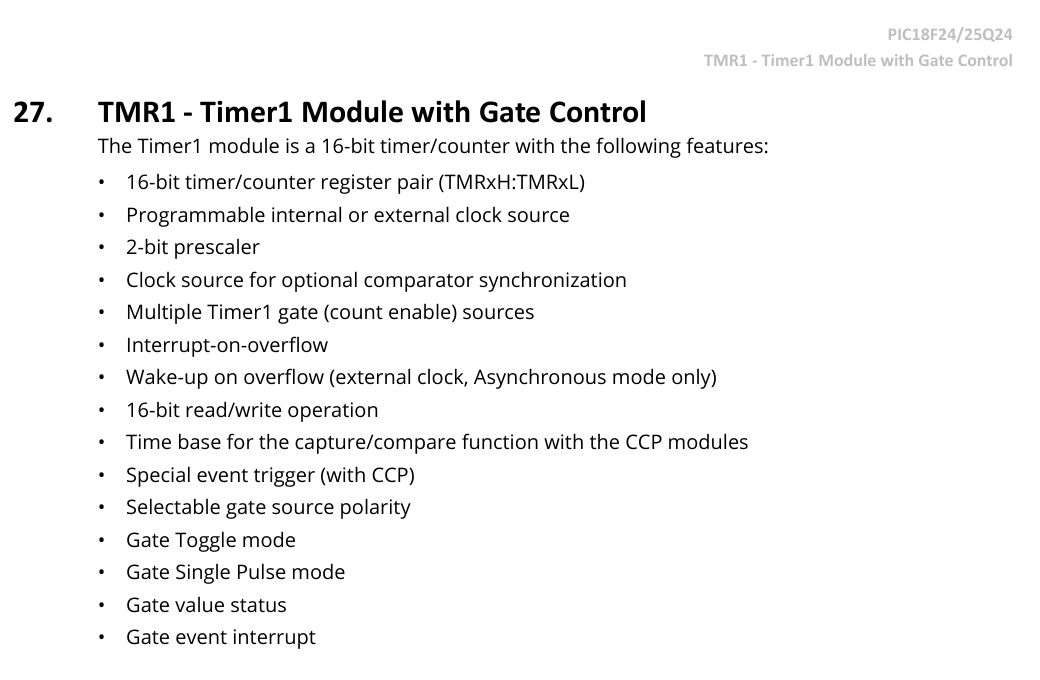
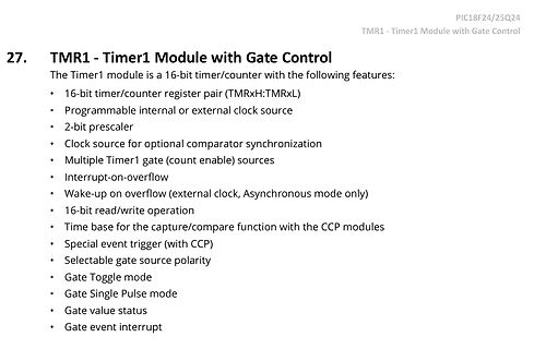
Beschreibung des TMR1 Timer1 Moduls
27. TMR1 - Timer1 Module with Gate Control PIC18F24/25Q24 TMR1 - Timer1 Module with Gate Control The Timer1 module is a 16-bit timer/counter with the following features: • 16-bit timer/counter register pair (
in „PIC Mikrocontroller noch aktuell ?“ · Mikrocontroller und Digitale Elektronik · · Screenshots
-
Datei
IICTSUS.ASM
list p=16f628A ;************************************************************** ;* Pinbelegung ;* ---------------------------------- ;* PORTA: ;* 0 - ;* 1 CLK in ;* 2 SDA in ;* 3 - ;* 4 - ;* 5 - ;* 6 - ;* 7 - ;
-
Datei
main.c
****************************************************** // // LED-Wecker unter Verwendung des // // PIC 16F716 // // // ************************************************************************************************ // **********************************************************************************
in „Stört mein Motor seinen PIC?“ · Mikrocontroller und Digitale Elektronik ·
-
Datei
FP.TXT
; RCS Header $Id: fp24.a16 2.7 1996/10/07 13:50:29 F.J.Testa Exp $ ; $Revision: 2.7 $ ; PIC16 24 BIT FLOATING POINT LIBRARY ; ; Unary operations: both input and output are in AEXP,AARG ; ; Binary operations: input in AEXP,AARG
in „Kann assembler file nicht builden“ · Mikrocontroller und Digitale Elektronik ·
-
PDF
schematics.pdf
C32 8Mhz POHALL3 L 3 PIU102 PC11 VCAP_1 PIU031 PC 100nF PIU103 PIU047 POFFUAU L T PIU102 PC12 VCAP_2 3 PC13 P0 P7 PI C PIU403 PC14-OSC32_IN(PC14) C16 C17 C PIU104 PC15-OSC32_OUT(PC15) P0 P7 2.2µF 2.2µF STM32F405RGT6 GND GND GND GND Title D
in „BLDC Motorcontroller 200A 48V basierend auf VESC“ · Analoge Elektronik und Schaltungstechnik ·
-
Datei
main.c
/* LCD SOFTWARE * ------------------------------------------------- * Hardware: * PIC PIN LCD-Pin Funktion * * 1 GND * 2 VDD +5V * 3 Kontrast (ca.8,2V) * RB4 13 4 I/OC1 * RB5 12 5 R/W * RB6 11 6 EX (enable) * RC0 16 7 DB0 * RC1 15 8 DB1 * RC2 14 9 DB2 * RC3 7 10 DB3 * RC4 6 11 DB4 *
in „[PIC]LCD mit m50530 Controler“ · Mikrocontroller und Digitale Elektronik ·
-
 Bild
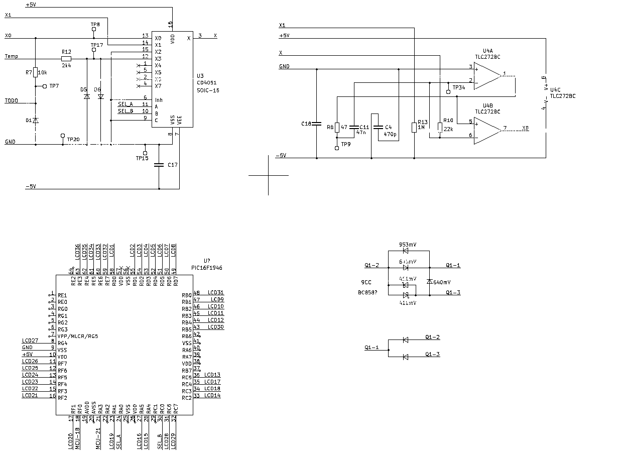
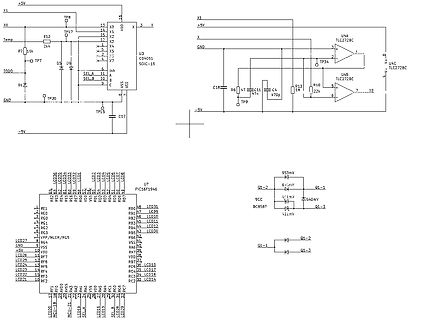
Schaltplan mit Operationsverstärkern und Mikrocontroller-Anschlüssen
X1, +5V, TP8, X0, R12, Temp, 2k4, X2, X3, X, U3 CD4051 SOIC-16, VDD, VEE, -5V, X5, X6, X7, SEL A, SEL B, Inh, A, B, C, D1, TODO, TP7, TP20, GND, TP15, C17, U4A TLC272BC, TP34, U4C TLC272BC, X0, R16, 22k, U4B TLC272BC, C18, R6, C11, 47n, C14, 470p, TP9, U7 PIC16F1946, LCD27 bis LCD14, VPP/MCLR/RG5, VSS, +5V, LCD26, LCD25, LCD24, LCD23, LCD22, LCD21, RF1 bis RF7, MCLR/RA5, RB0 bis RB7, VDD, VSS, RA0 bis RA7, RC0 bis RC7, LCD31 bis LCD14, SEL A, SEL B, 953mV
in „Ersa RDS 80 - Defekte Bauteile (Schaltplan benötigt)“ · Mikrocontroller und Digitale Elektronik · · Schaltpläne
-
Datei
MAIN.C
#include <pic16f6x.h> #define __CONFIG INTIO /* * Calculate preload value for one second timer */ #define PERIOD 1000000 // period in uS - one second here #define XTAL 4000000 // crystal frequency - 4MHz #define
in „Ich verstehe das nicht ....“ · Mikrocontroller und Digitale Elektronik ·
-
PDF
CP1_20201222.pdf
PI3A0 D E PIV408 D E PI5A08D E PIV608 D E PV7A0 D E PIVA08 D E PIV9A8 D E PI1008 D 20 GPA3 25 R45 1206 1k V5 F 16 E A F 16 E A F 16 E A F 16 E A F 16 E A F 16 E A F 16 E A F 16 E A F 16 E A F 16 E A PID020 INTA GPA4 PI102 CO65 1206 PI40NL N PI1A16 FF G H PIVA06 F FG H PI3A16 FF G H PIVA06 F FG H PV5A16F
in „Lerncomputer so wie KOSMOS CP1 nachbauen“ · Mikrocontroller und Digitale Elektronik ·
-
PDF
circuit.pdf
5 / 4 1 t D F R - S o l a r 5 0 3 9 0 2 / 1 0 . 1 10 0 . 1 Q 0 A C T 2 1 1 2 V T S A 4 L i Regulator . 8 C E Y 2 R V O3 . 3 V S V s s S V I N E H B EHs5 H b m 1 0 0 1 G A 4 t & S 1 0 0 3 O 6 8 0 4 N E 0 5 C 1 2 0 4 Sy 1 0 0 2 E H PIC16F627A-1/S0 2 0 0 2 1 0 0 1 1 0 0 2 D e t e c t o r Voltage (3V) 1 0 0 1 B 8 P F OpenD r a i n 1 0 0 2
in „Steuerplatine Solar Rollladenmotor 12V“ · Haus & Smart Home ·
-
Datei
spi.c
#include <stdio.h> #include <stdlib.h> #include <xc.h> #include <pic16f15244.h> #include <xc.h> #include "rfm69registers.h" #include "spi.h" #define _XTAL_FREQ 1000000 volatile char bufferflag = 0; void init_spi() { //RB4 is clock , RB6 is SDI miso , RC2 enable, RB7
in „PIC16f15244 RFM69 sendet nicht“ · Mikrocontroller und Digitale Elektronik ·
-
Datei
uvbel.asm
list p=16f628 errorlevel -302 ;unterdrückt Warnungen ;************************************************************** ;* Leiterplatten-UV-Belichtungsgerät ;* ;* ;* PORTA:0 Taster UP ;Zeit erhöhen ;* 1 Taster DOWN
in „nochmal PIC 16F628 EEprom“ · Mikrocontroller und Digitale Elektronik ·
-
Datei
main.asm
LIST P=PIC12HV615 #include <p12HV615.inc> __config 0x3F8C ; __CONFIG _CONFIG1, _FOSC_INTOSCIO & _WDTE_ON & _PWRTE_ON & _MCLRE_OFF & _CP_ON & _IOSCFS_8MHZ & _BOREN_ON ;==========================================
in „JVC Autoradio steuern“ · Mikrocontroller und Digitale Elektronik ·
-
Datei
main.c
*******************************************************************/ /* */ /* LCD_Testprogramm mit PIC 16F1829 */ /* */ /******************************************************************************************/ #include <16F1829.H> #include "stdlib.h" #include "stdio.h" #include "string.h" #include
in „LCD-Ansteuerung über PIC 16F1829“ · Mikrocontroller und Digitale Elektronik ·
-
PDF
20002234D.pdf
1.7V VOUT V IN 976 k + C IN C OUT E 4.7 µF EN V FB 10 µF I A K 562 k A GND - L1 4.7 µH VOUT V IN SW 5.0V @ 300 mA 3.0V to 4.2V V OUTS V IN V OUTP 976 k + CIN COUT 4.7 µF EN VFB 10 µF N - 309 k L -
in „NRF24L01+ durch MCP1640 gestört?“ · Mikrocontroller und Digitale Elektronik ·
-
PDF
25040.pdf
www.microchip.com. © 2006 Microchip Technology Inc. DS21204E-page 3 25AA040/25LC040/25C040 FIGURE 1-1: HOLD TIMING CS 17 17 16 16 SCK 18 19 High-impedance SO n + 2 n + 1 n n n - 1 Don’t Care 5 SI n + 2 n + 1 n n n - 1 HOLD FIGURE 1-2: SERIAL INPUT TIMING 4 CS 12 2 11 Mode 1,1 7 8 3 SCK Mode 0,0 5 6
in „Eeprom Philip Pines Auslesen mit CH341“ · Fahrzeugelektronik ·
-
Datei
240x128.ASM
: * ; * ; * ; * ; * ;********************************************************************** list p=16f877 ; list directive to define processor #include <p16f877.inc> ; processor specific variable definitions __CONFIG _CP_OFF & _WDT_OFF & _BODEN_ON & _PWRTE_ON & _RC_OSC & _WRT_ENABLE_ON & _LVP_OFF & _
in „T6963C mit PIC 16F877“ · Mikrocontroller und Digitale Elektronik ·
-
PDF
37378-DI300.pdf
L R8 10V 1 IC1 3 10k HT1036 SMD T2 SMD 2 C2 D5 9 R6 Aus 3 D 5 k D 47k C4 D7 V DS R 0 S SMD 13 100p Z 1 BC848 100u Z1 SMD SMD 16V Ein IC2 3,6V 8 GND Vcc 1 k 7 GP0 GP5 2 R 6 Q1 5 6 GP1 GP4 3 R3 1M 5 GP2 GP3 4 455
in „Mos-Fet wird heis“ · Analoge Elektronik und Schaltungstechnik ·
-
PDF
37378-DI300.pdf
L R8 10V 1 IC1 3 10k HT1036 SMD T2 SMD 2 C2 D5 9 R6 Aus 3 D 5 k D 47k C4 D7 V DS R 0 S SMD 13 100p Z 1 BC848 100u Z1 SMD SMD 16V Ein IC2 3,6V 8 GND Vcc 1 k 7 GP0 GP5 2 R 6 Q1 5 6 GP1 GP4 3 R3 1M 5 GP2 GP3 4 455
in „Dimmer will nicht richtig dimmen“ · Mikrocontroller und Digitale Elektronik ·
-
Datei
1io.asm
h'04' ; FSR mit 85 laden movlw b'11111111' ; = PORT A 1 = Eingang ueber w movwf h'00' ; und FSR nach 85 (Trisa) laden zugross clrf h'0F' ; start movlw h'F7' ; Weil die bloeden Pic's kein compare (Vergleich) Befehl kennen movwf h'10' ; muss man sich das selber
in „Pic-Abfrage“ · Mikrocontroller und Digitale Elektronik ·
-
Datei
probieren.asm
; TID 10 Stellen Display Anzeige ; Überarbeitet Version von Marco Reinke (DG1YIQ) ; Features: Festtext ; Anpassung an Atmega 8 von PIC 16F88 ; Version v0.2 .include "m8def.inc" ;Include Datei Atmega8 ;--- Reset und Interruptvectoren; VNr. Bezeichnung begin: rjmp main ; 1 Power
in „Hat schonmal einer ein Opel TID ->erfolgreich<-angesteuert ?“ · Mikrocontroller und Digitale Elektronik ·
-
Datei
I2C_test.asm
------------------------------------------------------------------------------------------- list p=16f887 ; festlegen welcher PIC #include <p16f887.inc> ; einbinden der .INClude - Datei ; Config-Word 1 & 2: __CONFIG _CONFIG1, _LVP_OFF & _FCMEN_OFF & _IESO_OFF & _BOR_OFF & _CPD_OFF & _CP_OFF & _MCLRE_ON
in „Welchen Takt einstellen (I2C)“ · Mikrocontroller und Digitale Elektronik ·
-
Datei
ini.txt
rrorlevel -302 #include <P16f873a.inc> #define zero STATUS,Z #define carry STATUS,C bank1 macro bsf STATUS,RP0 bcf STATUS,RP1 endm bank0 macro bcf STATUS,RP0 bcf STATUS,RP1 endm W EQU H'0000' F EQU H'0001' cblock 0x20 temp,prozentt
in „pic16f873a--PORTA0-4“ · Mikrocontroller und Digitale Elektronik ·
-
PDF
MCP41010.pdf
Figure 2-25 Resistor Terminals Voltage Range V A,B,W 0 — V DD Note 4 Capacitance (Aor CB) — 15 — pF f = 1 MHz, Code = 80h, see Figure 2-30 Capacitance CW — 5.6 — pF f = 1 MHz, Code = 80h, see Figure 2-30 Dynamic Characteristics (All dynamic characteristics use V5V) DD Bandwidth -3dB BW — 1 — MHz V
in „Widerstand regeln“ · Mikrocontroller und Digitale Elektronik ·
-
PDF
11195c.pdf
Figure 2-25 Resistor Terminals Voltage Range V A,B,W 0 — V DD Note 4 Capacitance (Aor CB) — 15 — pF f = 1 MHz, Code = 80h, see Figure 2-30 Capacitance CW — 5.6 — pF f = 1 MHz, Code = 80h, see Figure 2-30 Dynamic Characteristics (All dynamic characteristics use V5V) DD Bandwidth -3dB BW — 1 — MHz V
in „DC-DC Wandler mit MCP42010“ · Mikrocontroller und Digitale Elektronik ·
-
PDF
mcp41xxx.pdf
Figure 2-25 Resistor Terminals Voltage Range V A,B,W 0 — V DD Note 4 Capacitance (Aor CB) — 15 — pF f = 1 MHz, Code = 80h, see Figure 2-30 Capacitance CW — 5.6 — pF f = 1 MHz, Code = 80h, see Figure 2-30 Dynamic Characteristics (All dynamic characteristics use V5V) DD Bandwidth -3dB BW — 1 — MHz V
in „Schaltregler, Feedback und Op Amp“ · Analoge Elektronik und Schaltungstechnik ·
-
PDF
Datenblatt.pdf
910 kΩ 91 kΩ D1 0.1 µF 5.1 VZ Output 9 Common 7 VREF Rp 1 IBIAS Offset 100 kΩ VSS Input 20 kΩ Digital Voltage 4 Ground (0 to 10V) Analog Ground Component Selection F/S Freq. C REF C INT 1 kHz 2200 pF 4700 pF 10 kHz
in „Frequenz-Spannungswandler OP-Verstärkung“ · Mikrocontroller und Digitale Elektronik ·
-
Datei
user.c
char input_buffer[64]; char output_buffer[64]; char channel; int samples[5]; rom char welcome[]={"PIC18F4550 Full-Speed USB - CDC RS-232 Emulation Demo\r\n\r\n"}; rom char ansi_clrscr[]={"\x1b[2J"}; // ANSI Clear Screen Command /** P R I V A T E P R O T O T Y P E S **********************************
in „usb und pic18f2550“ · Mikrocontroller und Digitale Elektronik ·
-
Datei
CAN_RS232.asm
Processor 18F258 include p18F258.inc CONFIG OSC = HS CONFIG WDT = OFF TEMP1 equ 0x00 ;Temp-Register FF equ 0x0c ;ASCII Form Feed CR equ 0x0d ;ASCII Carriage Return LF equ 0x0a ;ASCII Line Feed BS equ 0x08 ;ASCII Back
in „PIC18F258 sendet kein CAN-Telegramm“ · Mikrocontroller und Digitale Elektronik ·
-
Datei
read_cf_as.asm
list p=16f877 include p16f877.inc count1 equ 0x20 ;Zählervariblen count2 equ 0x21 count3 equ 0x22 lo_byte0 equ 0x30 ;Ergebniszelle hi_byte0 equ 0x31 ;Ergebniszelle lo_byte1 equ 0x32 ;Ergebniszelle hi_byte1 equ
in „CompactFlasch-Karte im Memory Mode ansteuern“ · Mikrocontroller und Digitale Elektronik ·
-
PDF
Aim_TTi_QL_Series_II_Service_Manual_48511-1740.pdf
, R19, R111 ,R117, R122-123 ,R130, 23105-2120 RES SM0805 1K20F W1 R20 23105-2150 RES SM0805 1K50F W1 R29 23105-2220 RES SM0805 2K20F W1 R109 23105-2470 RES SM0805 4K70F W1 R16-18, R112 ,R121 23105-2510 RES SM0805 5K10F W1 R21-22 ,R132 23105-2560 RES SM0805 5K60F
in „wegen Aim TTi Netzteil Qualität“ · Analoge Elektronik und Schaltungstechnik ·
-
PDF
TBC-Enhancer_User-Manual_ENG.pdf
. Accordingly the [Pic 1/2] and [Pic 1 +2] keys can be used to control the freeze-frame - Practice: 1. Freeze a video with the freeze-frame function and then experiment with the [Pic 1/2] and the [Pic 1+2] keys. 2. Freezeasportsrecordingoranotherrecordingwithfastcameramovementandnotetheflickering.Nowexperimentwiththe
in „TBC-Enhancer (electronic design) funktioniert nicht“ · Mikrocontroller und Digitale Elektronik ·
-
Datei
Test_5.asm
; ; Testprogramm ; list p=16F627 ; Prozessortyp wird ausgewählt! include "P16F627.inc" ; die Include Datei mit vielen Festlegungen wird geladen ; z.B. die Standartnamen für wichtige Register und Bits festgelegt __CONFIG _BODEN_ON
in „PIC16F627 , Warteschleife“ · Mikrocontroller und Digitale Elektronik ·
-
PDF
MachXO2FamilyDataSheet.pdf
Architecture MachXO2 Family Data Sheet Figure 2-4. Slice Diagram FCO To Different Slice/PFU Slice FXB OFX1 FXA A1 CO F1 B1 F/SUM C1 D1 LUT4 & D Q1 Carry Flip-flop/ Latch CI To M1 Routing M0 LUT5 From Mux Routing OFX0 A0 CO B0 C0 LUT4 & F0 D0 Carry F/SUM D Q0 CI Flip-flop/ Latch CE CLK LSR Memory & FCI From
in „Statemachine springt in falsche "states" warum?“ · FPGA, VHDL & Co. ·
-
Datei
compile_kicad_mw_debug.txt
static_cast< wxGLCanvas* >( const_cast< HIDPI_GL_CANVAS* >( this ))->GetBackingScaleFactor(); //#else return 1.0f; //#endif >make -i kicad [ 0%] Built target polygon [ 67%] Built target bitmaps [ 67%] Generating version string header -- Using Git to determine build version string. -- Found Git: /usr/bin/git (
in „KiCad 5.0.2 - Absturz beim Footprint-Editor Aufruf“ · Platinen ·
-
Datei
GlobalDefinitions.h
double Temperature; double Humidity; double Battery_Voltage; double Sensor_Capacity; }substation_Type1; //Lightsensor typedef struct { uint16_t RAW_Red; uint16_t RAW_Green; uint16_t RAW_Blue; uint16_t RAW_Clear; int8_t gain; uint16_t blue; uint16_t red; uint16_t green; uint16_t clear; }Light_Type1; //
in „interner RTC oder externer“ · Mikrocontroller und Digitale Elektronik ·
-
PDF
Code_fuer_Zimmerbeleuchtung__Stand_25.09.2019_.pdf
#include "config.h" #include <xc.h> #include <pic16f688.h> //Zimmerbeleuchtung für das Haus #define RAUM_1a PORTAbits.RA0 //1. LED für Raum 1 liegt an Port A RA0 #define RAUM_1b PORTAbits.RA1 //2. LED für Raum 1 liegt an Port A RA1 #define RAUM_2a
in „PIC 16F688 Timereinstellung / Timerstart“ · Mikrocontroller und Digitale Elektronik ·
-
PDF
CAN_monitor_with_MAX32.pdf
canM od1(CAN::CAN1); //thisobjectusesCANm odule1 CAN canM od2(CAN::CAN2); //thisobjectusesCANm odule2 uint8_t CAN1M essageFifoArea[2*8*16]; uint8_t CAN2M essageFifoArea[2*8*16]; staticvolatileboolisCAN1MsgReceived
in „Microchip springt auf den Arduino Zug auf“ · Mikrocontroller und Digitale Elektronik ·
-
 Bild
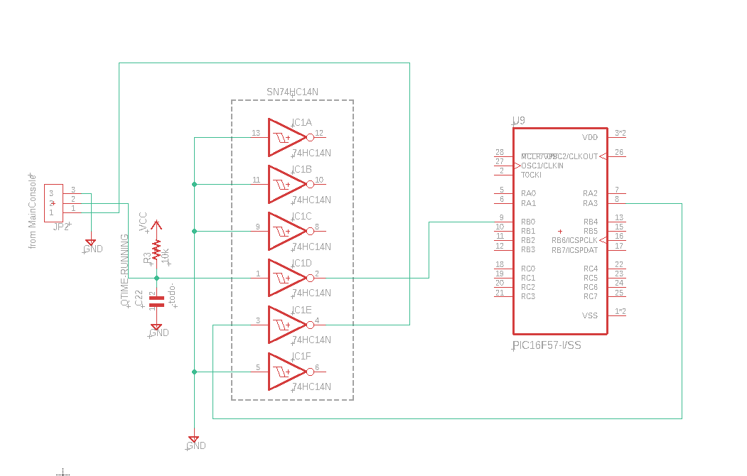
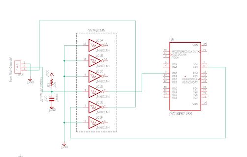
Schaltplan mit SN74HC14N und PIC16F57-I/SS
from MainConsole, JP2, VCC, GND, R3 10k, TIME_RUNNING, SN74HC14N, 1C1A, 1C1B, 1C1C, 1C1D, 1C1E, 1C1F, U9, PIC16F57-I/SS, MCLR/VPP, OSC1/CLKIN, TOCKI, VDD, RA0, RA1, RA2, RA3, RB0, RB1, RB2, RB3, RB4, RB5, RB6/ICSPCLK, RB7/ICSPDAT, RC4, RC5, RC6, RC7, VSS
in „Schmitt-Trigger 74HC14 mit Level Shifter“ · Mikrocontroller und Digitale Elektronik · · Schaltpläne
-
Datei
NEW_MAP.txt
// FIRMWARE REPLACEMENT FOR CHATPAD's pic16f883 // see attached documents to learn more // release 0.3.1 from jean : giancarlotodone at yahoo dot it // for the Open Keyboard Project // thanks alot to Gidi (who owns an half of my chatpad, call
in „Chatpad PIC16F883“ · Mikrocontroller und Digitale Elektronik ·
-
PDF
MSP-EXP430G2_LaunchPad.pdf
F2xx 16-bit Ultra-Low-Power Microcontroller, 1kB Flash, 128B RAM, 16-Bit Sigma-Delta A/D, USI for SPI/I2C MSP430F2011 F2xx 16-bit Ultra-Low-Power Microcontroller, 2kB Flash, 128B RAM, Comparator MSP430F2012
in „gutes Übersetzungsprogramm für Datenblätter gesucht“ · Offtopic ·
-
 Bild
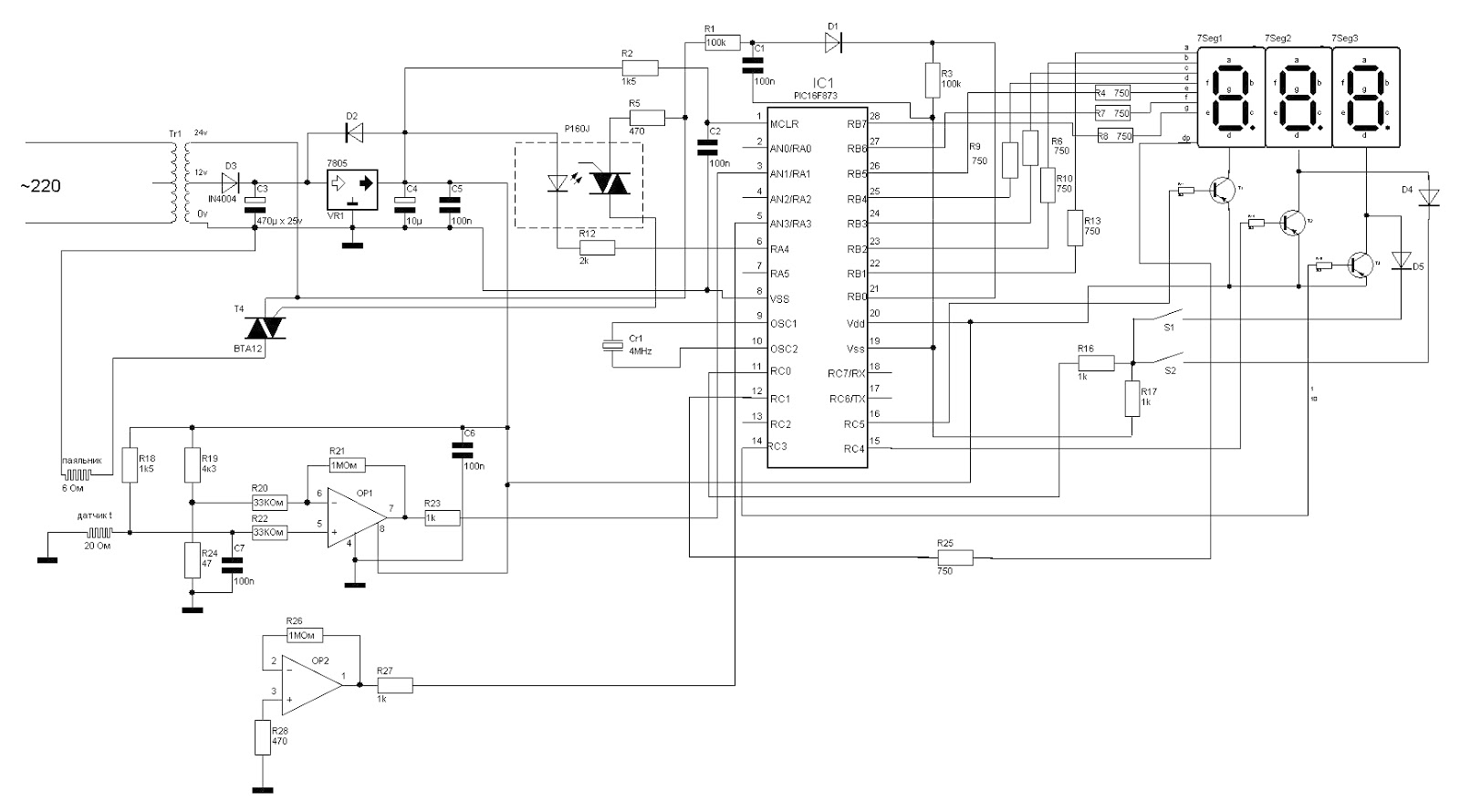
Schaltplan mit Mikrocontroller und 7-Segment-Anzeige
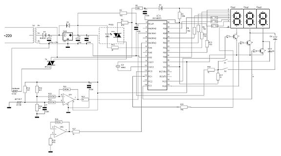
~220 Tr1 24v D3 1N4004 0v R2 1k R1 100k C1 D1 IC1 PIC16F873 MCLR RB7 7Seg1 7Seg2 7Seg3 R3 100k R4 750 R5 100n C2 470 P160J R6 750 R7 750 R8 750 R9 750 R10 750 R13 750 R16 750 R17 750 R20 330k R21 1M R22 750 R23 750 R24 20 Ohm R25 750 R26 1M R27 1k R28 47u C6 100n C7 100n T4 BTA12 S1 S2 Vdd Vss AN0 bis AN4 RA0 bis RA5 RC0 bis RC6 OP1 OP2
in „Weller WSD81 Fehlermeldung“ · Mechanik, Gehäuse, Werkzeug · · Schaltpläne
-
Datei
led.c
/******************************************************************/ /*LED Demo for PIC16F877 by MH */ /******************************************************************/ void delay(uns8 ms) // Unterprogramm zum Abwarten einer { // angegebenen Anzahl von Millisekunden while(ms){ // Schleife
-
 Bild
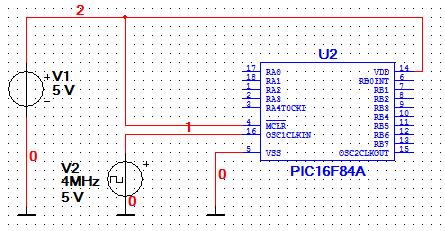
Schaltplan mit PIC16F84A Mikrocontroller
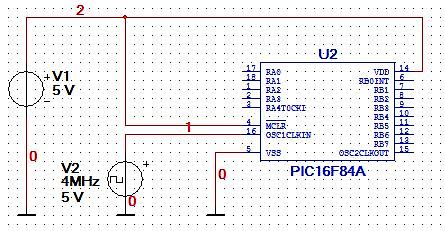
2 V1 5V 18 RA5 1 RAS 2 RAS 3 RA4TOCKI 4 MCLR 16 OSC1CLKIN 5 VSS 0 V2 4MHz 5V 0 U2 14 VDD 6 RB0INT 7 RB1 8 RB2 9 RB8 10 RB4 11 RB5 12 RB6 13 RB7 15 OSC2CLKOUT PIC16F84A
in „Multisim - PIC Schaltung arbeitet nicht!“ · Mikrocontroller und Digitale Elektronik · · Schaltpläne
-
PDF
MT2278_Abstract_1_.pdf
purpose of this paper is twofold; to demonstrate the concept of Pulse Oximetry using a Microchip dsPIC30F Digital Signal Processor and as an entrant into the 2007 Microchip 16-Bit Embedded Control Design Contest sponsored by Microchip and Circuit Cellar. Over the past number of years I have had experience
in „Oximeter im Eigenbau“ · Mikrocontroller und Digitale Elektronik ·