Package Outline (K4) b3 A E E1 c2 4 L3 θ1 D1 H D 1 2 3 L4 L5 Note 1 View B b2 e b Front View Rear View Side View Gauge Plane A1 Seating L2 Plane θ L L1 View B Note: 1. Although 4 terminal locations are shown, only 3 are functional. Lead number 2 was removed. θ Symbol A A1 b b2 b3 c2 D D1 E E1 e H L L1 L2
500 http://deb.debian.org/debian bookworm/main amd64 Packages [/code] Mischen von unstable/sid und stable Paketen kann man auch machen, führt aber oft wg. nicht erfüllbaren Abhängigkeiten zu Problemen. Sollte man die Finger von lassen, wenn man nicht dazu bereit ist das nachher auch selber wieder
0.1 Transceiver height, rear D 13.4 ± 0.1 Transceiver width, rear E 1.0 Maximum Extension of front sides outside of cage, see Note 2 Figure 1B F 2.3 Reference Location of cage grounding springs from centerline, top G 4.2 Reference Location of side cage grounding springs from top H 2.0 Maximum Width of
features two PCB Transport placement head: the high-precision Direction Pick & Place Head is on one side and the 6-Nozzle or the 12-Nozzle high-speed Collect & Place Head is on the other side of the gantry. When ordering a SIPLACE F 5HM it is possible to choose between the 6-Nozzle and the 12-Nozzle high
collections.deque functionality. • Add keypad_demux.DemuxKeyMatrix: use multiplexer for one side of a keypad matrix. • Add integration-based debouncing to keypad. • supervisor.Runtime.serial_bytes_available now returns a count instead of a bool. • Incompatible change: floppyio
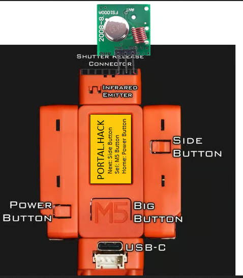
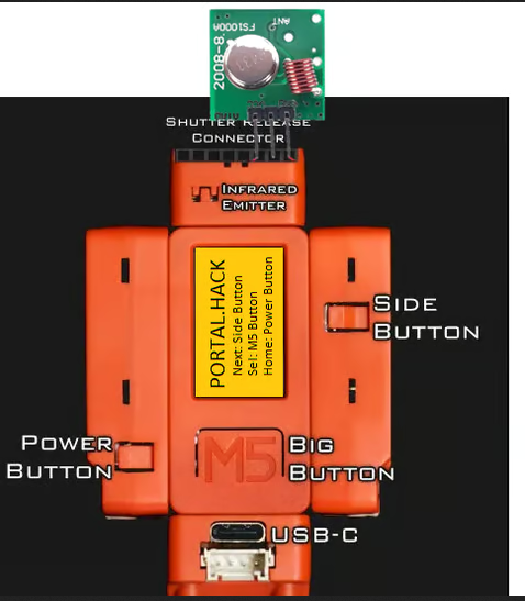
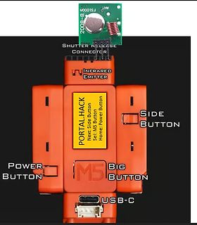
ANT FS1000A 2008-8 SHUTTER RELEASE CONNECTOR INFRARED EMITTER PORTAL.HACK Next: Side Button Sel: M5 Button Home: Power Button SIDE BUTTON POWER BUTTON M5 BIG BUTTON USB-C
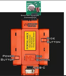
ANT 2008-8 SHUTTER RELEASE CONNECTOR INFRARED EMITTER PORTAL.HACK Next: Side Button Sel: M5 Button Home: Power Button SIDE BUTTON POWER BUTTON M5 BIG BUTTON USB-C
.......................................... 28 9.1 10K loading (Line Out / Surround / Center LFE / Side Surround) Frequency Response 28 9.2 10K loading (Line Out / Surround / Center LFE / Side Surround) Passband Ripple....29 9.3 10K loading (Line Out / Surround / Center LFE / Side Surround) THD+N Curve
voltage and constant current regulation The iW1817 is a high performance with PrimAccurate™ primary-side-only feedback AC/DC power supply control device which uses digital control ●● AccuSwitch™ technology with integrated 800V bipolar technology to build peak-current junction transistor (BJT) modePWMflybackpowersupplies. ●● Primary-side sensing technology eliminates opto- This device includes an internal isolators and simplifies design power BJT and operates in quasi- ●● DIP package for higher power and for single-sided board resonant
...............................................................86 8.10 Valid Part Numbers and Top Side Marking........................................................................87 9. REVISION HISTORY.................................................................................................
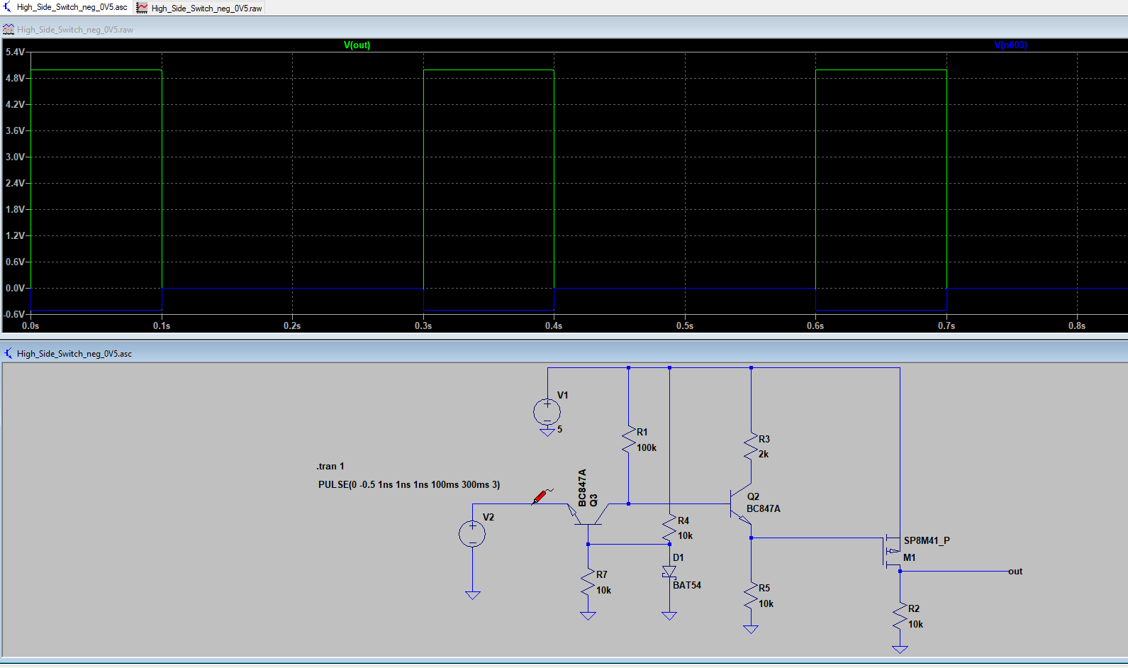
Du das mit einem Relais erledigen, im besseren Fall machst Du das mit einem Mosfet, der als High-Side-Switch zwischen Stromversorgung des Lüfters und dem Lüfter hängt, den Du dann mit einem der Ausgänge Deines BananaPi ansteuerst. Die Massen beider Stromquellen müssen natürlich miteinander verbunden
das mit einem Relais erledigen, im > besseren Fall machst Du das mit einem Mosfet, der als High-Side-Switch > zwischen Stromversorgung des Lüfters und dem Lüfter hängt, den Du dann > mit einem der Ausgänge Deines BananaPi ansteuerst. > > Die Massen beider Stromquellen müssen natürlich miteinander
primary current can Trises the output voltage rise period. be calculated with Equation (9): Primary-Side Inductor Design (Lm) Pin The HF500-30 uses internal slope av (9) Vin(min) compensation to support CCM and duty cycle exceeding 50% working condition. Use K to P The peak value of the primary current
Anhalter Ins All. https://hoerspiele.dra.de/kurzinfo.php?WGT=Per%20Anhalter%20ins%20All%20(Langfassung)&SID https://archive.org/details/05-adams-douglas-per-anhalter-ins-all/01++AdamsDouglas+-+Per+Anhalter+ins+All.mp3
Ins All. > https://hoerspiele.dra.de/kurzinfo.php?WGT=Per%20Anhalter%20ins%20All%20(Langfassung)&SID > https://archive.org/details/05-adams-douglas-per-anhalter-ins-all/01++AdamsDouglas+-+Per+Anhalter+ins+All.mp3 Danke für den Tipp, hab mal reingehört, scheint ja eine komplette Neuanfertigung zu
and to save on the cost of the primary protector ● Using such a technique will require a robust PHY side protection device and one such option is the SPLV2.8-4 shown below. It should be noted that this device will only provide differential protection between the data pairs. ● If longitudinal and differential
frequencies.This simple approach may try 400V at 500A, which is correct for the V130LA20A; to have undesirable side effects, such as a) unwanted prove the correctness of our “educated guess” we resonances with inductive components located elsewhere in calculate I, the circuit leading to high peak voltages; b) high
available on the Allegro website. 2The Allegro evaluation board has 1500 mm of 2 oz. copper on each side, connected to pins 1 and 2, and to pins 3 and 4, with thermal vias connect- ing the layers. Performance values include the power consumed by the PCB. Further details on the board are available from
voltage source generated photovoltage and current are available at powered by an input LED. The input side of the the output pins of the device. If no more current is photovoltaic MOSFET driver consists of an LED. produced from the solar cells, a capacitive load will Current flow causes the LED to emit light
1 L A B H0 W D 4 5 W 2 L 1 P 0 D0 Direction of Unreeling Cross Section A-B Figure 1 t Reel Upper Side n Type Direction of a Unreeling c Lower Side w 1 Cross Section w 2 Optional Shape: Circular or Polygonal Figure 2 Warning ■ Users should independently evaluate the suitability of and test each product
the flyback converter, age (V , 200V/div), the supply voltage (V , 5V/div), the L lk1is the primary-side leakage inductance, n is the turns ds CC feedback voltage (V fb, 1V/div), and the drain current (I ,d ratio of the transformer, R sn is the snubber resistance, and 0.2A/div), respectively. The maximum
____________ 17 xPort® Pro Embedded Device Server Integration Guide 4 List of Figures Figure 2-1. Side View of the xPort Pro____________________________________ 8 Figure 2-2. xPort Pro Block Diagram _____________________________________ 8 Figure 2-3. xPort Pro LEDs ___________________________________
Krone das Dach z.T. überragt. Wenn die explodiert wird wohl das Dach dran glauben. On the positive side haben wir inzwischen FTTH und also mit Kupfertelefonie kein Problem mehr. Dieter D. schrieb im Beitrag #7667648: > Möglich, aber es könnte trotzdem noch die Schrittspannung des > abfließenden Blitzstromes
does not require any additional circuitry to translate between the different bus voltages. When one side of the PCA9515 is pulled LOW by a device on the I C-bus, a CMOS hysteresis type input detects the falling edge and causes an internal driver on the other side to turn on, thus causing the other side
muss ehrlich zugeben, dass ich mit der Digikey Suche nicht so vertraut war und deshalb gerade Low Side Gate Driver nicht mit UVLO gefunden habe, da der Parameter in der Suche wo man das angeben kann nicht vorhanden ist. Nach langer Suche habe ich es dann aufgegeben und habe einen mit High Side Variante
muss ehrlich zugeben, dass ich mit der Digikey Suche nicht so vertraut war und deshalb gerade Low Side Gate Driver nicht mit UVLO gefunden habe, da der Parameter in der Suche wo man das angeben kann nicht vorhanden ist. Nach langer Suche habe ich es dann aufgegeben und habe einen mit High Side
and AUX lanes. In this particular application the AC coupling capacitors are shown on the connector side. The AC coupling capacitors may also be placed on the signal path on controller side. The AUX+ line must be pulled-down weakly through a resistor to ground and the AUX– line must be pulled-up weakly
zwei 5V Netzteile parallel geschaltet, Funktionsüberwachung mit kleinem µC und Shunts am GND (LowSide) der Netzteile. Netzteile per Justierung auf 5,1V gestellt und von Hand "ausbalanciert" Zur Notversorgung eine ideale Diode und StepDown mit Speisung aus Autobatterie, eingestellt auf 4,9 oder 5V
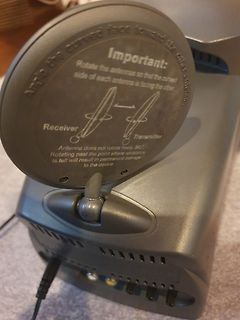
Important:
Rotate the antennas so that the curved
side of each antenna is facing the other
Receiver Transmitter
Antenna does not rotate freely 360°.
Rotating past the point where resistance
is felt will result in permanent damage
to the device.
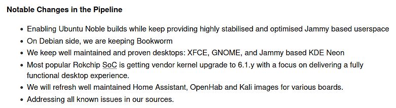
Noble builds while keep providing highly stabilised and optimised Jammy based userspace
• On Debian side, we are keeping Bookworm
• We keep well maintained and proven desktops: XFCE, GNOME, and Jammy based KDE Neon
• Most popular Rokchip SoC is getting vendor kernel upgrade to 6.1.y with a focus on delivering
controlled soldering irons, set at 270°C, with special-tips to contact all solder-joints from both sides of the package at the same time, remove part with tweezers when pad solder is liquid. May 2023 152/154 Rev. 1.3 Micro Crystal DTCXO Temp. Compensated Real-Time Clock Module RV-3032-C7 13.PACKING &
START=60&OFFSET=30&CCOUNTRY=628&LANGUAGE=de&CCOUNTRY=628&LANGUAGE=de&CCOUNTRY=628&LANGUAGE=de&nbc=1&SID=9287a89daf4f151446ae48f4aab07db41bcb19c007d7d258c6846 schlagen einheitlich 2,2 kOhm vor. Zur Mikrofonempfindlichkeit gibt es eine Schalldruck-Pegelangabe bei 1 kHz bezogen auf 1V/Pascal, meistens um
wäre. https://juris.bundesgerichtshof.de/cgi-bin/rechtsprechung/document.py?Gericht=bgh&Art=en&sid=0&client=3&nr=30855&pos=0&anz=1 Nachdem also der TO (= Käufer) von ebay den Kaufpreis zurückerhalten hat, muss der Verkäufer sich mit dem TO wegen des weiterhin offenen Kaufpreises selber streiten
msg5150607/#msg5150607 Außerdem ist selbst der 8er deutlich „moderner“ als das, was es bei Debian (incl. SID) gibt :( https://www.mikrocontroller.net/topic/567558#7664444
msg5150607 > > Außerdem ist selbst der 8er deutlich „moderner“ als das, was es bei > Debian (incl. SID) gibt :( > > https://www.mikrocontroller.net/topic/567558#7664444 Ja, klar, es gibt immer wieder alte Projekte, wo das dann durch immer mehr features zum Problem wird. Allerdings ist dieses Komponententesterprojekt
Oder muss ich beim einschalten der PWM eine bestimmte Reihenfolge beachten? Z.B. erst 50% nur low side für ein paar Zyklen und dann high aktivieren? Und ein ganz komisches Phänomen hab ich noch gehabt: als ich den lüfter im laufenden Betrieb abgesteckt habe ist der Controller gestorben (hoher Stromverbrauch
seinMCUDas Ausgangslogiksignal ist direkt mit dem verbundenEG2132auf dem Eingangskanal. Die High-Side-High-Side- und Low-Side-Low-Side-Ausgangstreiber können bis zu sinken1,5Aund maximaler Ausgangsstrom bis zu1A,High-End-Oberarmkanal kann ertragen300VSpannung ist die Leitungsverzögerung zwischen dem
effect sensors should have low pass filters. A simple RC network works. Input: None. Output: None. Side Effects: None. Overview: This interrupt represent Hall C ISR. Hall C -> RB5 -> IC8. This is generated by the input Capture Channel IC8. The purpose of this ISR is to Calculate the actual mechanical
# of ENABLE pins nd PCA9515 21 1 communication with the other side. In the 2 case, both DesignCon 2003 TecForum I C Bus Overview 64 masters are located in each side of the PCA9515 and the control is basically the same as above for the 400 Slide 64 kHz devices. Due
the fault current or high ambient temperature is of foils and leads. The foils are attached on both sides of the removed and/or the power is switched off, the polymer starts polymer sheet. One lead is connected to a foil by soldering. cooling, recrystallizing, shrinking, and restoring the device to a The

 Bild
Bild
 Bild
Bild
 Bild
Bild
 Bild
Bild
 Bild
Bild
 Bild
Bild
 Bild
Bild
 Bild
Bild
 Bild
Bild
 Bild
Bild
 Bild
Bild