-
PDF
project.pdf
P P P P P P P P P P P P P P V V C33 100nF 6 7 8 9 0 1 2 3 4 5 6 7 8 9 0 1 2 3 4 5 6 7 8 9 0 STM32F407VGT6 +5V +5V P2 +5V P3 2 2 2 2 3 3 3 3 3 3 3 3 3 3 4 4 4 4 4 4 4 4 4 4 5 M1OUTA 1 M2OUTA 1 R21 2 R23 2 +3.3V 3.3k 3.3k GND C38 P10 ENC1B 3 8 ENC2B 3 8 +3.3V 6 k 0 7 X X +3.3V 1 N 4 C 4 C R 1 5 R T R
in „Schaltplan so richtig? STM32F407VG“ · Mikrocontroller und Digitale Elektronik ·
-
PDF
project.pdf
P P P P P P P P P P P P P P V V C33 100nF 6 7 8 9 0 1 2 3 4 5 6 7 8 9 0 1 2 3 4 5 6 7 8 9 0 STM32F407VGT6 +5V +5V P2 +5V P3 2 2 2 2 3 3 3 3 3 3 3 3 3 3 4 4 4 4 4 4 4 4 4 4 5 M1OUTA 1 M2OUTA 1 R21 2 R23 2 +3.3V 3.3k 3.3k GND C38 P10 ENC1B 3 8 ENC2B 3 8 +3.3V 6 k 0 7 X X +3.3V 1 N 4 C 4 C R 1 5 R T R
in „Schaltplan so richtig? STM32F407VG“ · Mikrocontroller und Digitale Elektronik ·
-
 Bild
Bild
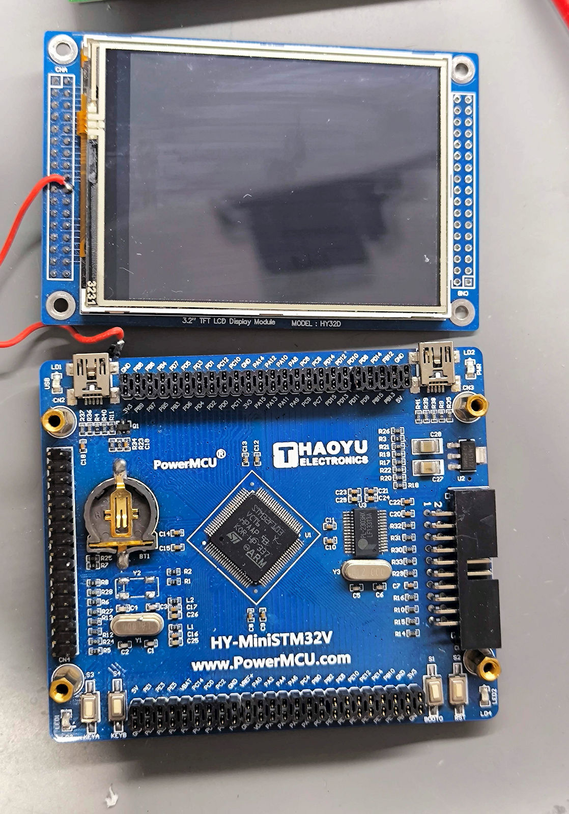
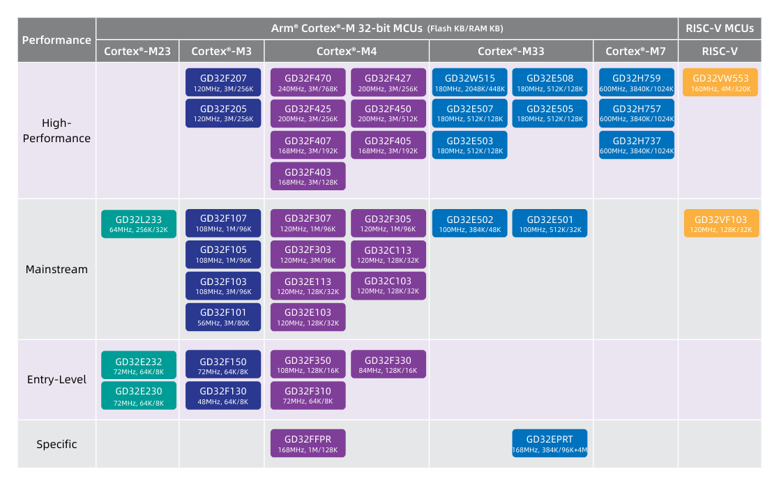
Mikrocontroller-Board mit TFT-Display
3.2" TFT LCD Display Module MODEL: HY32D PowerMCU THAOYU ELECTRONICS STM32F407VGT6 ARM HY-MiniSTM32V www.PowerMCU.com
in „[V] Diverse Evaluation-Boards - ca. 2014-2016“ · Markt · · Platinenfotos
-
Datei
eeprom.c
!= SUCCESS) return 0xff; /* Wichtiger Hinweis, bzgl der Reihenfolge des Bit Setzens, Manual. STM32F407, S834 Die Konfiguration muss VOR dem Buszugriff erfolgen, d.h. das Datenbyte wird erst ganz zum Schluss ausgelesen */ // NACK einstellen E2PROM anzuzeigen, dass keine weiteren Daten angefordert sind
in „STM32F4xx: 24LC512 EEPROM Zugriffsroutinen“ · Projekte & Code ·
-
Datei
eeprom.c
!= SUCCESS) return 0xff; /* Wichtiger Hinweis, bzgl der Reihenfolge des Bit Setzens, Manual. STM32F407, S834 Die Konfiguration muss VOR dem Buszugriff erfolgen, d.h. das Datenbyte wird erst ganz zum Schluss ausgelesen */ // NACK einstellen E2PROM anzuzeigen, dass keine weiteren Daten angefordert sind
in „Organisation der Header und Includes“ · Mikrocontroller und Digitale Elektronik ·
-
 Bild
Bild
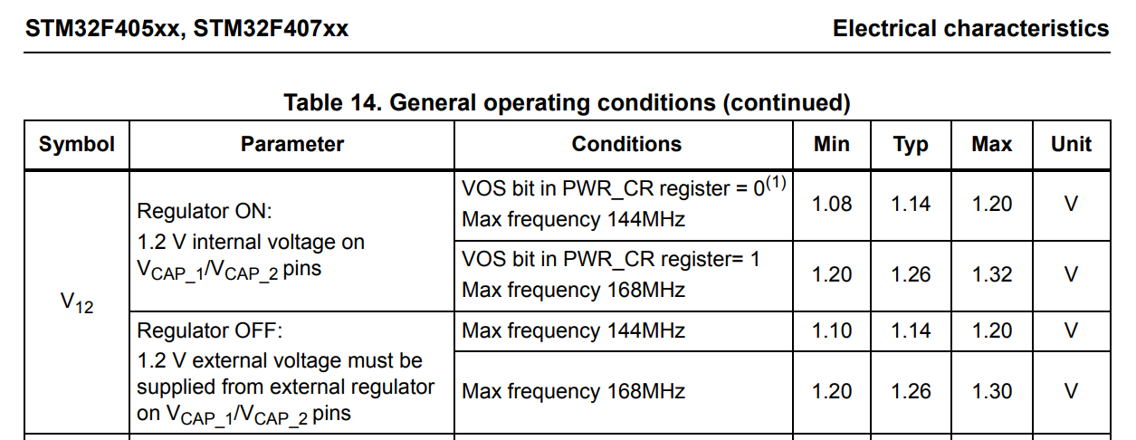
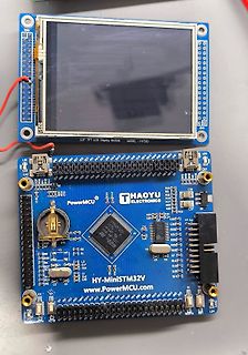
Tabelle der elektrischen Charakteristiken eines STM32F405xx Mikrocontrollers
STM32F405xx, STM32F407xx Electrical characteristics Table 14. General operating conditions (continued) Symbol Parameter Conditions Min Typ Max Unit V12 Regulator ON: 1.2 V internal voltage on VCAP_1/VCAP_2 pins VOS bit in
in „STM32F4 zieht zu viel Strom“ · Mikrocontroller und Digitale Elektronik · · Screenshots
-
 Bild
Bild
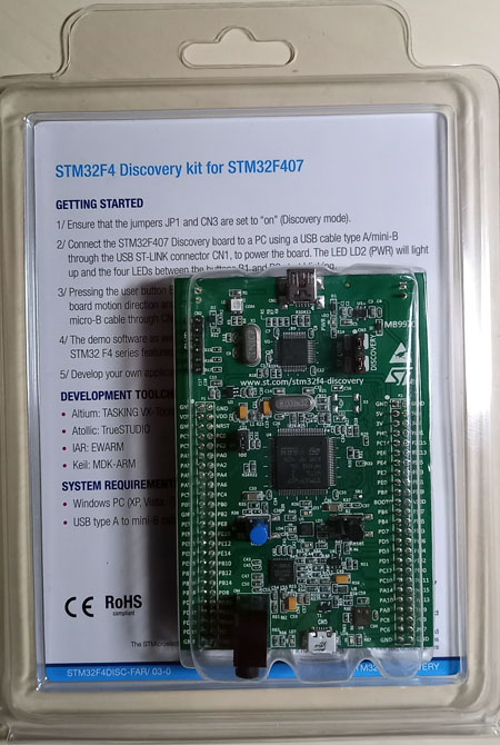
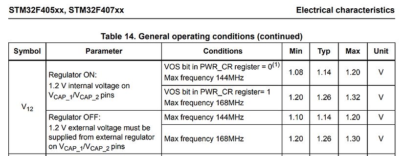
STM32F4 Discovery kit in Verpackung
STM32F4 Discovery kit for STM32F407 GETTING STARTED 1/ Ensure that the jumpers JP1 and CN3 are set to "on" (Discovery mode). 2/ Connect the STM32F4 Discovery board to a PC using a USB cable Type A/mini-B through the USB ST-LINK connector
in „[V] Evalboards, passive Bauteile, Netzteile, Relais,.“ · Markt · · Platinenfotos
-
PDF
STM32F4-BASE_BRD.pdf
E E E R1 C2 L L L 1 SV2 20 1 SV3 10 01.03.2012 03:41:16 C:\Users\SuperK\13-Eagle\1-Projekte\STM32F407Vx_Baseboard\STM32F4-BASE.brd
in „STM32F407 (100pin) Basisboard - Review bitte“ · Mikrocontroller und Digitale Elektronik ·
-
Datei
eeprom.c
!= SUCCESS) return 0xff; /* Wichtiger Hinweis, bzgl der Reihenfolge des Bit Setzens, Manual. STM32F407, S834 Die Konfiguration muss VOR dem Buszugriff erfolgen, d.h. das Datenbyte wird erst ganz zum Schluss ausgelesen */ // NACK einstellen E2PROM anzuzeigen, dass keine weiteren Daten angefordert sind
in „GCC Optimierung killt Funktion“ · Mikrocontroller und Digitale Elektronik ·
-
Datei
eeprom.c
!= SUCCESS) return 0xff; /* Wichtiger Hinweis, bzgl der Reihenfolge des Bit Setzens, Manual. STM32F407, S834 Die Konfiguration muss VOR dem Buszugriff erfolgen, d.h. das Datenbyte wird erst ganz zum Schluss ausgelesen */ // NACK einstellen E2PROM anzuzeigen, dass keine weiteren Daten angefordert sind
in „Lebensdauer von lokalen Variablen“ · Softwareentwicklung ·
-
PDF
3DSanner_Stromlaufplan1.pdf
VCAP1 P$81 TDI P$138 PA15 PE0 P$169 FSMC_BLN0 P$6 VBAT VCAP2 P$125 PB0 P$56 PB0 PF15 P$65 A9 STM32F407IGT6 C17 C18 PB1 P$57 PB1 PF14 P$64 A8 PB2 P$58 PB2 PF13 P$63 A7 2.2nF 2.2nF B TDO/SWO P$162 PB3 PF12 P$59 A6 B JTAG=> TRST P$163 PB4 PF11 P$28 USB1_OVRCURR PB5 P$164 PB5 PF10 P$27 GND GND GND SCPB7
in „STM32 Boot0 Problem“ · Mikrocontroller und Digitale Elektronik ·
-
 Bild
Bild
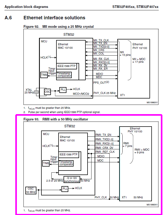
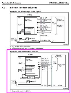
Blockschaltbilder Ethernet-Schnittstellen STM32
Application block diagrams STM32F405xx, STM32F407xx A.6 Ethernet interface solutions Figure 92. MII mode using a 25 MHz crystal STM32 MCU Ethernet MAC 10/100 HCLK(1) MII TX_CLK MII TX_EN MII TXD[3:0] MII CRS MII COL MII RX_CLK MII RXD[3:0] MII RX_DV
in „STM32F4x7, Ethernet, DP83848I“ · Mikrocontroller und Digitale Elektronik · · Screenshots
-
PDF
STM32F4-BASEbrd.pdf
72C R1 C2 e L L L S 1 SV2 20 1 SV3 10 01.03.2012 18:44:54 C:\Users\SuperK\13-Eagle\1-Projekte\STM32F407Vx_Baseboard\STM32F4-BASE.brd
in „STM32F407 (100pin) Basisboard - Review bitte“ · Mikrocontroller und Digitale Elektronik ·
-
Datei
ARM-STM32F4-Serie-Daten.txt
Zähler: 14 Timer Prozessor-Serie: ARM Cortex-M Art des Programmspeichers: Flash Serie: STM32F4 STM32F407VGT6 ============= ARM Mikrocontroller - MCU ARM M4 1024 FLASH 168 Mhz 192kB SRAM Kern: ARM Cortex M4 Datenbus-Weite: 32 bit Maximale Taktfrequenz: 168 MHz Programmspeichergröße: 1024 kB RAM-Datengröße
in „STM32F407VGT6 Pinkompatibilität zu den F427/F437 Typen ?“ · Mikrocontroller und Digitale Elektronik ·
-
 Bild
Bild
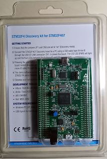
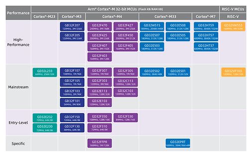
Übersichtstabelle der Arm Cortex-M und RISC-V Mikrocontroller
120MHz, 3M/256K GD32F450 200MHz, 3M/512K GD32E507 180MHz, 512K/128K GD32H757 600MHz, 3840K/1024K GD32F407 168MHz, 3M/192K GD32F403 168MHz, 3M/128K Mainstream GD32L233 64MHz, 256K/32K GD32F107 108MHz, 1M/96K GD32F307 120MHz, 1M/96K GD32F305 120MHz, 1M/96K GD32E502 100MHz, 384K/48K GD32E501 100MHz, 512K/32K
in „Neuer WCH-Mikrocontroller, IoT-Datenfunkupdates, MaixPy und mehr“ · Mikrocontroller und Digitale Elektronik · · Screenshots
-
Datei
Blinky.txt
********************** // Hardwarebasis: F4DISCOVERY // Programm: Blinky // Mikrocontroller: STM32F407VG (ARM 32-bit CORTEX-M4) // Speicher: 1MB FLASH, 192KB SRAM // Taktfrequenz: Quarz: 8MHz, mit PLL auf: 168MHz // Stand: 16.12.2012 // IDE/Compiler: CooCox CoIDE 1.5.1 //*****************************
in „Delay für STM32F4Discovery“ · Mikrocontroller und Digitale Elektronik ·
-
Datei
build.xml
STM32F4XX"/> <define name="USE_STDPERIPH_DRIVER"/> <define name="__ASSEMBLY__"/> <define name="STM32F407VG"/> </defineset> <!-- include compile path --> <includepath path="."/> <includepath path="cmsis"/> <includepath path="CoOS/kernel"/> <includepath path="CoOS/portable"/> <includepath path="cmsis_boot
in „STM32F4 CoOS“ · Mikrocontroller und Digitale Elektronik ·
-
Datei
stm32-families.txt
DIE413 STM32F405O(E-G)Yx DIE413 STM32F405RGTx DIE413 STM32F405VGTx DIE413 STM32F405ZGTx DIE413 STM32F407I(E-G)Hx DIE413 STM32F407I(E-G)Tx DIE413 STM32F407V(E-G)Tx DIE413 STM32F407Z(E-G)Tx DIE413 STM32F415OGYx DIE413 STM32F415RGTx DIE413 STM32F415VGTx DIE413 STM32F415ZGTx DIE413 STM32F417I(E-G)Hx DIE413
in „Controller mit größerem Flash als angegeben?“ · Mikrocontroller und Digitale Elektronik ·
-
PDF
file.pdf
Hardware and layout UM1472 Figure 6. STM32F407VGT6 block diagram ##-▯DATA▯2!-▯▯▯▯+" %XTERNAL▯MEMORY #,+▯▯.%▯;▯▯▯=▯▯!;▯▯▯▯= CONTROLLER▯▯&3-# $;▯▯▯▯=▯▯/%.▯▯7%.▯▯ .*4234▯▯*4$)▯▯ !("▯ 32!-▯▯032!-▯▯./2▯&LASH▯ .",;▯▯▯=▯▯.,▯▯.2%' *4$/▯37$▯▯*4$/ *4!'▯▯▯
in „STM32 FW_LIB wozu dient RCC_APB2PeriphClockCmd?“ · Mikrocontroller und Digitale Elektronik ·
-
PDF
TOBBY.pdf
applications) Microcontroller ARM STM32F107VC :90 DMIPS, 256KB Flash, 64KB RAM, 12Bit ADC or ARM STM32F407VE: 210 DMIPS, 512KB Flash, 192KB RAM, 12 Bit ADC incl. micro SD-card socket, USB, Ethernet RJ45 Drive 2 Gear boxed mini DC-motors (3-6VDC) incl. driver circuit and encoder disk (50 or 100 increments
in „TOBBY THE ROBBY“ · Markt ·
-
Datei
main.cpp
/ check against system clock timeStart = us_ticker_read(); } int main() { printf("Hello from STM32F407VE\n"); initHardwareTimeout(); int timeout = 2000; // µs startHardwareTimeout(timeout); ThisThread::sleep_for(1000); // sleep for 1s and let timeout ISR execute int measuredDiff = timeNow-timeStart;
in „STM32F407 OnePulse Timer“ · Mikrocontroller und Digitale Elektronik ·
-
Datei
EclipseInstallation.txt
Cross ARM C Linker - General: Pfad zum Linkerskript einfügen: "${workspace_loc:/${ProjName}/stm32f407_flash.ld}" - Libraries: (-l) m c Karteireiter Toolchains: - Karteireiter Build Steps - Pre-Bild Steps: (zeigt die Compilerversion bei jedem Kompiliervorgang) ${cross_prefix}${cross_c}${cross_suffix}
in „Ambilight mit STM32F4discovery und TVP5150AM1“ · Mikrocontroller und Digitale Elektronik ·
-
Datei
linker.ld
--------------------------------------- * Linker script for running in internal FLASH on the STM32F407VG *----------------------------------------------------------------------------*/ OUTPUT_FORMAT("elf32-littlearm", "elf32-littlearm", "elf32-littlearm") OUTPUT_ARCH(arm) SEARCH_DIR(.) /* Memory Spaces
in „STm32Fxxx: Kleiner Gefallen vom einem Profi erbeten“ · Mikrocontroller und Digitale Elektronik ·
-
Datei
stm32f4xx_ram.ld
*************************************** * History: * * 03.06.2012 mifi First Version for the stm32f407ig, based on an * example from the CMSIS packages of ARM. * 27.12.2012 mifi Tested with STM32F4-Discovery too. * 16.02.2013 mifi Align bss and heap too. **********************************************
in „ARM - Probleme mit sprintf (Linkerfehler)“ · Mikrocontroller und Digitale Elektronik ·
-
Datei
arm-gcc-link_-_Kopie.ld
***************************** ** ** File : stm32_flash.ld ** ** Abstract : Linker script for STM32F407VG Device with ** 1024KByte FLASH, 192KByte RAM ** ** Set heap size, stack size and stack location according ** to application requirements. ** ** Set memory bank area and size if external memory is
in „Hardfault-Interrupt bei malloc wenn kein Speicher verfügbar“ · Mikrocontroller und Digitale Elektronik ·
-
Datei
spi_oled.c
#include "STM32F4xx.h" #include "_mcpr_stm32f407.h" #include "spi_oled.h" #include "tools.h" #include "timer.h" void spiInit(void) { //CONFIGURE I/Os FOR SPI2 //SCLK = PB13 setOutputPort(B, 13, ALTERNATIVE, PUSHPULL, HIGH, LOWSTATE); //AFRH Register
in „0,96 Oled mit STM32F407“ · Mikrocontroller und Digitale Elektronik ·
-
Datei
build_console.txt
ffunction-sections -Os -std=c99 -g -c -D__FPU_USED -DSTM32F4XX -DUSE_STDPERIPH_DRIVER -D__ASSEMBLY__ -DSTM32F407VG -IC:\CooCox\CoIDE\workspace\STM32F4_Discovery_CoOS -IC:\CooCox\CoIDE\workspace\STM32F4_Discovery_CoOS\cmsis -IC:\CooCox\CoIDE\workspace\STM32F4_Discovery_CoOS\CoOS\kernel -IC:\CooCox\CoIDE\workspace
in „STM32F4 CoOS“ · Mikrocontroller und Digitale Elektronik ·
-
Datei
spi_oled.c
#include "STM32F4xx.h" #include "_mcpr_stm32f407.h" #include "spi_oled.h" #include "tools.h" #include "timer.h" void spiInit(void) { //CONFIGURE I/Os FOR SPI2 //SCLK = PB13 setOutputPort(B, 13, ALTERNATIVE, PUSHPULL, HIGH, LOWSTATE); //AFRH Register
in „0,96 Oled mit STM32F407“ · Mikrocontroller und Digitale Elektronik ·
-
Datei
stm32-families.txt
DIE413 STM32F405O(E-G)Yx DIE413 STM32F405RGTx DIE413 STM32F405VGTx DIE413 STM32F405ZGTx DIE413 STM32F407I(E-G)Hx DIE413 STM32F407I(E-G)Tx DIE413 STM32F407V(E-G)Tx DIE413 STM32F407Z(E-G)Tx DIE413 STM32F415OGYx DIE413 STM32F415RGTx DIE413 STM32F415VGTx DIE413 STM32F415ZGTx DIE413 STM32F417I(E-G)Hx DIE413
in „Controller mit größerem Flash als angegeben?“ · Mikrocontroller und Digitale Elektronik ·
-
PDF
MB997.pdf
POPC133 PC13 PIU407PC13 BOOT0 PIU4094BO T0 PIR300PIR3001 PIR210PIR2102 PIC2701 PIC2702 I2 0 STM32F407VGT6 R0 6.8pF VDD U4B4B POBO T0 R313 COSB1 PISB15PISPOPC15 PIU401VDD5 VSS5 PIU4010 10K I0 SCOSB15 Not Fitted PIU401VDD12 VSS4 PIU4027 R2 L1L CR23 PIU402VDD4 VSS2 PIU4074 PIL101 PIL102PIR230PIR2301 PIU405VDD1
in „Mit STM32F4 einen Laser ansteuern“ · Mikrocontroller und Digitale Elektronik ·
-
Datei
stm32_flash.ld
***************************** ** ** File : stm32_flash.ld ** ** Abstract : Linker script for STM32F407VE Device with ** 512KByte FLASH, 192KByte RAM ** ** Set heap size, stack size and stack location according ** to application requirements. ** ** Set memory bank area and size if external memory is used
in „STM32F4 C++ springt bei __libc_init_array in den HardFault“ · Mikrocontroller und Digitale Elektronik ·
-
Datei
I2CPort.cpp
* Taken from Tutorial * https://sites.google.com/site/johnkneenmicrocontrollers/18b-i2c/i2c_stm32f407#linki2cpins */ #include "I2CPort.h" #include <stdio.h> #include <stdlib.h> #include "diag/Trace.h" I2CPort::I2CPort(unsigned int port, unsigned int sdaPin, unsigned int sclPin): _port(port), _sdaPin
in „I2C auf dem STM32 F411RE“ · Mikrocontroller und Digitale Elektronik ·
-
Datei
error.txt
/opt/cmake-3.26.4-linux-x86_64/bin/cmake --build /home/jojo/projects/mbed-ce-hello-world/build/JZ_F407VE_STM32CUBE-Debug --config Debug --target flash-Fingerprint -- exited with code: 1 [driver] Build completed: 00:00:02.168 [build] Build finished with exit code 1
in „C++: Callback Funktion kann nicht aufgelöst werden“ · Mikrocontroller und Digitale Elektronik ·
-
PDF
sammelbestellung.pdf
STM32F4DISCOVERY Hersteller: STMicroelectronics 1 Versand sofort Beschr.: Entwicklungsboards und Kits - ARM STM32F407 HIGH PERF DISCOVERY BOARD RoHS: RoHS-konform 8,87 € 8,87 € Mouser-Nr.: 511-STM32F3DISCOVERY 1 Verfügbarkeit Herst.- Nr.: STM32F3DISCOVERY 0 Versand sofort Hersteller: STMicroelectronics 1 Im Lieferrückstand
-
Datei
build_output.txt
compiled. [cc] arm-none-eabi-gcc -mcpu=cortex-m4 -mthumb -Wall -ffunction-sections -g -O3 -c -DSTM32F407VG -DSTM32F4XX -DUSE_STDPERIPH_DRIVER -IC:\projekte\examples -IC:\projekte\examples\tryWave\AudioPlayer1\cmsis -IC:\projekte\examples\tryWave\AudioPlayer1\STM32F4xx_StdPeriph_Driver\inc -IC:\projekte
in „STM32F4 Discovery Audio DAC CS43L22“ · Mikrocontroller und Digitale Elektronik ·
-
Datei
serial_stm32.c
/** @file serial_stm32.c @brief serial handling using CubeMx @platform developed on STM32F407 using ARM-CC @see for DMA receive see https://my.st.com/public/STe2ecommunities/mcu/Lists/STM32Java/Flat.aspx?RootFolder=https%3a%2f%2fmy.st.com%2fpublic%2fSTe2ecommunities%2fmcu%2fLists%2fSTM32Java
in „STM32 HAL UART Mysterium oder bin ich dumm?“ · Mikrocontroller und Digitale Elektronik ·
-
Datei
NF-Generator-407.c
/* STM32F407 www.mino-elektronik.de 2016-11-08 */ #include <stdio.h> #include <stdint.h> #include <stdlib.h> #include <stm32f4xx.h> #include <stm32f4xx_gpio.h> #include <stm32f4xx_rcc.h> // LCD-Routinen in anderem
in „Frequenz Erzeugung mit avr“ · Mikrocontroller und Digitale Elektronik ·
-
PDF
PitschLight_Doku_V1.2.pdf
letzten Änderung eines Parameters wird der aktuelle Stand der Parameter in den FLASH-Speicher des STM32F407 geschrieben, so dass die Parameter auch nach Abschalten der Versorgungsspannung beim späteren Einschalten wieder zur Verfügung stehen und verwendet werden. Nach Änderung eines Parameters sollte daher
in „Ambilight mit STM32F4discovery und TVP5150AM1“ · Mikrocontroller und Digitale Elektronik ·
-
Datei
compilerrun.txt
sp-d16 -mthumb -Wall -ffunction-sections -O0 -mfloat-abi=hard -g -c -DUSE_STDPERIPH_DRIVER -DSTM32F407VG -IX:\05_foreignSTM32solutions\AudioPlayer1\AudioPlayer1 -IX:\05_foreignSTM32solutions\AudioPlayer1\AudioPlayer1\cmsis -IX:\05_foreignSTM32solutions\AudioPlayer1\AudioPlayer1\cmsis_boot -IX:\05_foreignSTM32solutions
in „STM32F4 Discovery Audio DAC CS43L22“ · Mikrocontroller und Digitale Elektronik ·
-
Datei
SchaltTiny.txt
1001B0009C838B83109299001092980078948B8185 :1001C0009C810097A9F080917F008F5F80937F00D2 :1001D00080917F00853160F080917F008D3140F407 :1001E00089819A812B813C81820F931F9A83898315 :1001F00080917F008E31B8F2F89489819A8196952A :10020000879596958795969587952C010F900F90D9 :100210000F900F90CF91DF910895DF93CF93CDB7DB :10022000DEB727970FB6F894DEBF0FBECDBF9B8316
in „Hex Code in AtTiny25 übertragen“ · Mikrocontroller und Digitale Elektronik ·
-
Datei
myfirst.s
ldr r1, = RCC_AHB1ENR @ p. 242 und p. 266 manual RM00090 (Rev 18) @ dm00031020-stm32f405-415-stm32f407......pdf ldr r0, = BIT20+0x1f @ Enable Port A,B,C,D,E str r0, [r1] @ Set PORTB pins 10 and 11 in alternate function mode ldr r1, = GPIOB_MODER ldr r0, = 0x00A00280 @ 00000280 is Reset value for Port
in „Assemblerprogramm zur Ausgabe eines Zeichens auf UART3“ · Mikrocontroller und Digitale Elektronik ·
-
PDF
MK_STM32F4_Sensorboard_Schematic.pdf
_2_MOSI GND + 1 2 VREF+ PA3/USART2_RX USART2_RX C5 GND SDO 5 SPI3_2_MISO 1 CS SPI3_CS_BMA180 STM32F407VGT_SORT Not in use 6 NC 4 VREF+ 11 NC INT INT_BMA180 V U$100 V 2 4 5 0 0 12 NC 3 3 A A A B B B C C C C C C C C D E E E E E E GND NC D + + P P P P P P P P P P P P P P P P P P P P P D D D 4 VCC ENABLE
in „I2C-Kommunikation stoppt nach ca. 1-5 Sekunden“ · Mikrocontroller und Digitale Elektronik ·
-
PDF
MK_STM32F4_Sensorboard_Schematic-2.pdf
_2_MOSI GND + 1 2 VREF+ PA3/USART2_RX USART2_RX C5 GND SDO 5 SPI3_2_MISO 1 CS SPI3_CS_BMA180 STM32F407VGT_SORT Not in use 6 NC 4 VREF+ 11 NC INT INT_BMA180 V U$100 V 2 4 5 0 0 12 NC 3 3 A A A B B B C C C C C C C C D E E E E E E GND NC D + + P P P P P P P P P P P P P P P P P P P P P D D D 4 VCC ENABLE
in „EAGLE: Sprungfahnen“ · Platinen ·
-
Datei
HD66766_example.c
LCD Driver IC: Hitachi HD66766 // IM0=Low, IM1=High, 16-bit interface, 80-mcu-family // MCU: STM32 F407 VET6 // ========================================================(C) 2/2026 Ma_Baker============= // ======================================================================================== // Disclaimer
in „LCD-Modul F51661GNCJU-MLW-AA * Info *“ · Mikrocontroller und Digitale Elektronik ·
-
Datei
myfirst.s
ldr r1, = RCC_AHB1ENR @ p. 242 und p. 266 manual RM00090 (Rev 18) @ dm00031020-stm32f405-415-stm32f407......pdf ldr r0, = BIT20+0x1f @ Enable Port A,B,C,D,E str r0, [r1] @ Set PORTB pins 10 and 11 in alternate function mode ldr r1, = GPIOB_MODER ldr r0, = 0x00A00280 @ 00000280 is Reset value for Port
in „Assemblerprogramm zur Ausgabe eines Zeichens auf UART3“ · Mikrocontroller und Digitale Elektronik ·
-
Datei
myfirst.s
ldr r1, = RCC_AHB1ENR @ p. 242 und p. 266 manual RM00090 (Rev 18) @ dm00031020-stm32f405-415-stm32f407......pdf ldr r0, = BIT20+0x1f @ Enable Port A,B,C,D,E str r0, [r1] @ Set PORTB pins 10 and 11 in alternate function mode ldr r1, = GPIOB_MODER ldr r0, = 0x00A00280 @ 00000280 is Reset value for Port
in „STM32CubeIDE - kann man dem gdb server einen Schalter mitgeben?“ · Mikrocontroller und Digitale Elektronik ·
-
Datei
myfirst168.s
ldr r1, = RCC_AHB1ENR @ p. 242 und p. 266 manual RM00090 (Rev 18) @ dm00031020-stm32f405-415-stm32f407......pdf ldr r0, = BIT20+0x1f @ Enable Port A,B,C,D,E str r0, [r1] @ Set PORTB pins 10 and 11 in alternate function mode ldr r1, = GPIOB_MODER ldr r0, = 0x00A00280 @ 00000280 is Reset value for Port
in „STM32CubeIDE - kann man dem gdb server einen Schalter mitgeben?“ · Mikrocontroller und Digitale Elektronik ·
-
Datei
0800012c.asm
f807 lsr.w r8, r2, r7 8000322: 408b lsls r3, r1 8000324: ea48 0303 orr.w r3, r8, r3 8000328: fa26 f407 lsr.w r4, r6, r7 800032c: ea4f 4e13 mov.w lr, r3, lsr #16 8000330: fbb4 f9fe udiv r9, r4, lr 8000334: fa1f fc83 uxth.w ip, r3 8000338: fb0e 4419 mls r4, lr, r9, r4 800033c: 408e lsls r6, r1 800033e:
in „uint64_t auf STM32F103“ · Mikrocontroller und Digitale Elektronik ·
-
Datei
test_O1.asm
00000000 l d .debug_frame 00000000 .debug_frame 00000000 l df *ABS* 00000000 obj/cmsis/startup_stm32f407xx.o 0800028a l .text 00000000 LoopCopyDataInit 08000282 l .text 00000000 CopyDataInit 080002a2 l .text 00000000 LoopFillZerobss 0800029c l .text 00000000 FillZerobss 080002d0 l .text 00000000 Infinite_Loop
in „C++ Exceptions mit gcc-arm-none-eabi“ · Mikrocontroller und Digitale Elektronik ·
-
Datei
test_O2.asm
00000000 l d .debug_frame 00000000 .debug_frame 00000000 l df *ABS* 00000000 obj/cmsis/startup_stm32f407xx.o 0800028a l .text 00000000 LoopCopyDataInit 08000282 l .text 00000000 CopyDataInit 080002a2 l .text 00000000 LoopFillZerobss 0800029c l .text 00000000 FillZerobss 080002d0 l .text 00000000 Infinite_Loop
in „C++ Exceptions mit gcc-arm-none-eabi“ · Mikrocontroller und Digitale Elektronik ·