kam ich immer mit i2c au, dies kann das BTM222 nicht. Auch finde ich es langsam nervig ständig PCA9515 als i2c levelshifter einzusetzen. Werden teuer auf dauer, habe ich gerade nicht da und kriege ich bis zum Wochenende nicht. Gleiches gilt für UART levelshifter. Daher kam mir diese idee. Freue mich
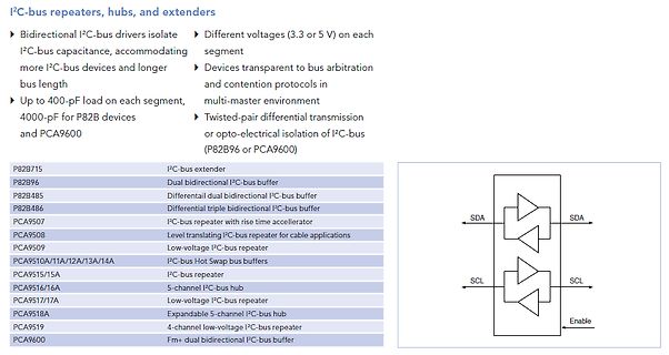
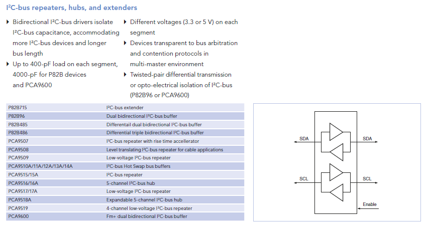
I²C-Bus eigentl. nur mit entsprechenden Treibern realisieren, z.B.: P82B715 I²C-Bus Extender PCA9515 I²C-Bus Repeater Mit dem SHT11 habe ich (durch die Verringerung des Pull-Ups an SDA auf 1k) aber auch schon Messwerte über ca. 2m Flachbandkabel übertragen.
wenn es unbedingt I²C sein soll dann könnte ein PCA9515 (100m bei 400khz) das Problem lösen. Sollte Übertragungsgeschwindigkeit keine Rolle spielen einfach die Frequenz herabsetzen.
Ja der AVR läuft mit 5V, dazwischen habe ich aber einen PCA9515 der zwischen 5V und 3V shiftet. Alle geposteten Messungen habe ich selbstverständlich auf der 3V Seite vorgenommen!
sehr sauber aus. der AVR läuft mit 5V/12 MHz, das Display mit 3.3V, dazwischen hängt sogar ein PCA9515 als Pegelwandler. Pullups sind 4k7 (jeweils am AVR und am Display) und 10k am Pegelwandler. ich bin mir nun nicht sicher, was mir das Display damit sagen will. Für "ich hab grad keine zeit" wäre
dann stimme ich Michl zu. Du solltest es mit Busextendern versuchen (z.B. dem PCA9513 oder dem PCA9515). Reiche Auswahl findest Du hier http://www.nxp.com/#/page/content=[f=/dynamic/datasheets/tid-71114_sid-41735/data.xml] mare_crisium
Geschwindigkeit s.o. Beispiel: I2C-Bus: gemeinsam 3.3V und 5V. MSP430 an 3,3V/5V: slaa148.pdf Philips PCA9515: I2C Puffer mit Pegelwandlung. Der PCA9515 ist ein I2C-Bus Repeater, welcher I2C Busse mit verschiedenen Spannungen isoliert. Verfügbar bei Reichelt und DigiKey. AN97055 von Philips, "Bi-directional
> sollte)? Du meinst z.B. 1,8V <-> 3,3V <-> 5V? Das kommt auf den Pegelwandler an. Mit dem PCA9515 z.B. geht es nicht (Details siehe Datenblatt), mit dem PCA9306 dagegen geht es. Mit der Simpelvariante miteinem MOSFET aus der Philips-Application-Note wäre ich vorsichtig, da der nach low schaltende
PCA9517 is unpowered. The 2.7 V to 5.5 V bus B-side drivers behave much like the drivers on the PCA9515A device, while the adjustable voltage bus A-side drivers drive more current and eliminate the static offset voltage. This results in a LOW on the B-side translating into a nearly 0 V LOW on the A-side
SDA und SCL haben keine zusätzliche Beschaltung. Der Raspberry besitzt aber einen I2C Repeater (PCA9515) ohne Pullups. Allerdings gehe ich nicht davon aus, dass diese Platine speziell für Rolladenmotoren ist. PE und N hätte man sich dafür sparen können. Auch die ungerade Zahl von 11 Relais spricht
without exceeding the 400 pF specs. A total of 400 pF would be allowed on each side of the interface. PCA9515 can also be used to link (just) two standard 400pF busses like this. It IS allowed to interconnect, say, 10 of these interfaces together on the ‘new’ bus formed by the linked TxD/RxD pins and thus
without exceeding the 400 pF specs. A total of 400 pF would be allowed on each side of the interface. PCA9515 can also be used to link (just) two standard 400pF busses like this. It IS allowed to interconnect, say, 10 of these interfaces together on the ‘new’ bus formed by the linked TxD/RxD pins and thus
Liebe Leute, laut Anhang ist im Datenblatt als typische Applikation links der Host mit 3,3V und rechts ein Slave mit 5V abgebildet. Bei mir ist es genau umgekehrt. Ich habe einen Atmega mit 5V und einen I2C Slave mit 3,3V. Kann ich den Baustein auch umgekehrt benutzen? Also Versorgung, Enable mit dem Slave links anschließen und den Host rechts. Ist das dem Bus egal? Wo ist denn der Unterschied beim I2C von Master und Slave am Bus? Freu mich auf Antworten. P.S. Aufgrund der Recherche hier im Forum, kenne ich die Möglichkeiten, SCA und SCL direkt mit 10k auf 3,3V zu legen, oder auch
fast mode plus I C-bus devices in additional to SMBus. The TCA9406 is not a bus buffer like the PCA9515A and PCA9517. It provides both level translation and physically isolates the capacitance to either side of the bus when both sides are connected. The I offfeature can be utilized to isolate the bus
similar buffers that rely on special logic thresholds for their operation, for example PCA9511, PCA9515, or PCA9518. The Sx/Sy side is only intended DESCRIPTION 2 2 The P82B96 is a bipolar IC that creates a non-latching, for, and compatible with, the normal I C logic voltage levels of I C 2 master and
similar buffers that rely on special logic thresholds for their operation, for example PCA9511, PCA9515, or PCA9518. The Sx/Sy side is only intended DESCRIPTION 2 2 The P82B96 is a bipolar IC that creates a non-latching, for, and compatible with, the normal I C logic voltage levels of I C 2 master and
similar buffers that rely on special logic thresholds for their operation, for example PCA9511, PCA9515, or PCA9518. The Sx/Sy side is only intended DESCRIPTION 2 2 The P82B96 is a bipolar IC that creates a non-latching, for, and compatible with, the normal I C logic voltage levels of I C 2 master and
similar buffers that rely on special logic thresholds for their operation, for example PCA9511, PCA9515, or PCA9518. The Sx/Sy side is only intended DESCRIPTION 2 2 The P82B96 is a bipolar IC that creates a non-latching, for, and compatible with, the normal I C logic voltage levels of I C 2 master and
similar buffers that rely on special logic thresholds for their operation, for example PCA9511, PCA9515, or PCA9518. The Sx/Sy side is only intended DESCRIPTION 2 2 The P82B96 is a bipolar IC that creates a non-latching, for, and compatible with, the normal I C logic voltage levels of I C 2 master and
similar buffers that rely on special logic thresholds for their operation, for example PCA9511, PCA9515, or PCA9518. The 2 Sx/Sy side is only intended for, and compatible with, the normal I C-bus logic voltage levels of I C-bus master and slave chips, or even Tx/Rx signals of a second P82B96 if required
segments using bus buffers, multiplexers or switches. Figure 43 shows an example of a bus that uses a PCA9515 buffer to deal with high bus capacitance. Each segment is then allowed to have the maximum capacitance so the total bus can have twice the maximum UM10204 All information provided in this document
segments using bus buffers, multiplexers or switches. Figure 43 shows an example of a bus that uses a PCA9515 buffer to deal with high bus capacitance. Each segment is then allowed to have the maximum capacitance so the total bus can have twice the maximum UM10204 All information provided in this document
segments using bus buffers, multiplexers or switches. Figure 43 shows an example of a bus that uses a PCA9515 buffer to deal with high bus capacitance. Each segment is then allowed to have the maximum capacitance so the total bus can have twice the maximum UM10204 All information provided in this document
segments using bus buffers, multiplexers or switches. Figure 43 shows an example of a bus that uses a PCA9515 buffer to deal with high bus capacitance. Each segment is then allowed to have the maximum capacitance so the total bus can have twice the maximum UM10204 All information provided in this document
segments using bus buffers, multiplexers or switches. Figure 43 shows an example of a bus that uses a PCA9515 buffer to deal with high bus capacitance. Each segment is then allowed to have the maximum capacitance so the total bus can have twice the maximum UM10204 All information provided in this document
segments using bus buffers, multiplexers or switches. Figure 43 shows an example of a bus that uses a PCA9515 buffer to deal with high bus capacitance. Each segment is then allowed to have the maximum capacitance so the total bus can have twice the maximum UM10204 All information provided in this document

 Bild
Bild