-
Datei
z80.asm
temp,0 bootwait2: dec temp brne bootwait2 pop temp dec temp brne bootwait1 .endif rcall printstr .db "CPM on an AVR, v1.0",13,0,0 rcall printstr .db "Initing mmc...",13,0 rcall mmcInit .if MEMTEST rcall printstr .db "Testing RAM...",13,0 ;Fill RAM ldi adrl,0 ldi adrh,0 ramtestw: mov temp,adrh eor temp
in „CP/M auf ATmega88“ · Mikrocontroller und Digitale Elektronik ·
-
 Bild
Bild
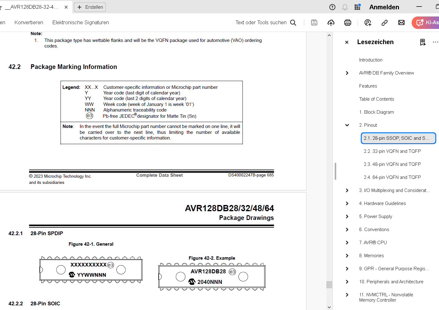
Datenblatt Ausschnitt AVR128DB Package Marking Information
information. © 2023 Microchip Technology Inc. and its subsidiaries Complete Data Sheet DS40002247B-page 685 AVR128DB28/32/48/64 Package Drawings 42.2.1 28-Pin SPDIP Figure 42-1. General XXXXXXXXXX e3 Y YWWNNN Figure 42-2. Example AVR128DB e3 2040NNN 42.2.2 28-Pin SOIC
in „AVR128DA64 TCA1 funktioniert nicht mit alternativen Output?“ · Mikrocontroller und Digitale Elektronik · · Screenshots
-
PDF
mikrobeginner_gesamt.pdf
Typdefinition in der def.inc eine Fehlermeldung resultiert. Das hat historische Grün- de, weil die ersten AVR-Typen noch gar keine Zeigerregister hatten. Damit ist unsere Notentabelle klar: hier ist sie. Notentabelle: .db 1<<CS01, 71 ; c' #9 .db 1<<CS00, 214 ; F #19 .db 1<<CS01, 169 ; a #0 .db 1<<CS01, 63 ;
in „Attiny26 PortD“ · Mikrocontroller und Digitale Elektronik ·
-
PDF
AVR_tutorial.pdf
einen kompatiblen (z.B. KS0070) und haben 14 oder 16 Pins. Die Pinbelegung ist praktisch immer gleich: 48 Pin # Bezeichnung Funktion 1 Vss GND 2 Vcc 5V 3 Vee Kontrastspannung (0V bis 5V) 4 RS Register Select (Befehle/Daten) 5 RW Read/Write 6 E Enable 7 DB0 Datenbit 0 8 DB1 Datenbit 1 9 DB2 Datenbit 2 10
in „AVR-Tutorial als PDF bzw *.doc“ · Mikrocontroller und Digitale Elektronik ·
-
PDF
kicad_8450_dcm_liste_neu_v3.pdf
TQFP32, 128K Flash, 16K RAM, 48MHz, CortexM0+ SAMD20E17A-MU QFN32, 128K Flash, 16K RAM, 48MHz, CortexM0+ SAMD20G14A-AU TQFP48, 16K Flash, 2K RAM, 48MHz, CortexM0+ SAMD20G14A-MU QFN48, 16K Flash, 2K RAM, 48MHz,
in „KiCAD Eeschema, Bibliotheksdokumentation *.dcm als PDF-Datei“ · Platinen ·
-
PDF
8-bit-MCU-Overview.pdf
3 ATmega324PB 44 32 2 1.8–5.5 20 10 8 2 2 2 1 1 1 1 5 AVR-DB Family 28-64 32-128 4–16 512 1.8–5.5 24 12 22 10 2-3 -4 9–18 3–7 1 1– 3–6 1–2 3 ATtiny42x/82x/162x/322x 14-24 4-32 0.5-3 128 1.8-5.5 20 12 15 6x 12 8 6 2 1 3 AVR-DA Family 28-64 32-128 4–16 512 1.8–5.5 24 12 22 10 -3 16 16 1 5 3–6 1–2 3 AVR-DD Family 14-32 16–64 2–8 256 1.8–5.5 24 12 23 10 1 16
in „Moderne AVR (Nachfolger Atmega und Attiny)“ · Mikrocontroller und Digitale Elektronik ·
-
PDF
8-bit-MCU-Overview.pdf
3 ATmega324PB 44 32 2 1.8–5.5 20 10 8 2 2 2 1 1 1 1 5 AVR-DB Family 28-64 32-128 4–16 512 1.8–5.5 24 12 22 10 2-3 -4 9–18 3–7 1 1– 3–6 1–2 3 ATtiny42x/82x/162x/322x 14-24 4-32 0.5-3 128 1.8-5.5 20 12 15 6x 12 8 6 2 1 3 AVR-DA Family 28-64 32-128 4–16 512 1.8–5.5 24 12 22 10 -3 16 16 1 5 3–6 1–2 3 AVR-DD Family 14-32 16–64 2–8 256 1.8–5.5 24 12 23 10 1 16
in „AVR®DD family, low pin count devices“ · Mikrocontroller und Digitale Elektronik ·
-
PDF
8-bit-MCU-Overview.pdf
3 ATmega324PB 44 32 2 1.8–5.5 20 10 8 2 2 2 1 1 1 1 5 AVR-DB Family 28-64 32-128 4–16 512 1.8–5.5 24 12 22 10 2-3 -4 9–18 3–7 1 1– 3–6 1–2 3 ATtiny42x/82x/162x/322x 14-24 4-32 0.5-3 128 1.8-5.5 20 12 15 6x 12 8 6 2 1 3 AVR-DA Family 28-64 32-128 4–16 512 1.8–5.5 24 12 22 10 -3 16 16 1 5 3–6 1–2 3 AVR-DD Family 14-32 16–64 2–8 256 1.8–5.5 24 12 23 10 1 16
in „AVR®DD family, low pin count devices“ · Mikrocontroller und Digitale Elektronik ·
-
PDF
AVR-ASM-Tutorial_16_05_08_v2.pdf
einem Timer?.........................................................................................128 13.10 Weblinks ...........................................................................................................................128 14 AVR-Tutorial: Uhr....................................
in „AVR-ASM-Tutorial: PDF 16.5.08“ · www.mikrocontroller.net ·
-
Datei
Ansteuerung_SED1374.asm
$F0,$48,$48,$70,$48,$48,$F0,$00 ; B .db $70,$88,$80,$80,$80,$88,$70,$00 ; C .db $F0,$48,$48,$48,$48,$48,$F0,$00 ; D .db $F8,$80,$80,$F8,$80,$80,$F8,$00 ; E .db $F8,$80,$80,$F0,$80,$80,$80,$00 ; F .db $70,$88
in „Strings im Flash“ · Mikrocontroller und Digitale Elektronik ·
-
Datei
Assembler.s
equ flashEnd = 0 .equ flashSize = 0 .equ intVectorSize = 0 .equ uartCount = 0 .equ stackEnd = 0 .equ AVR_CORE = 3 .equ AvrAccessHigh = 1 .device atmega32 .equ _CLOCK = 4000000 .equ stackSize = 128 .set FracDecimals = 7 ;avrEqus .equ bootStart = 0x0 .equ sramStart = 96 .equ sramEnd = 2143 .equ xramEnd =
in „ISR macht Newbie fertig :P“ · Mikrocontroller und Digitale Elektronik ·
-
PDF
XPLAIN_Shematic.pdf
TILLER D NORWAY Date: 08.05.2009 15:10:18 PAGE: 1 of 5 Document number: A08-0551 Revision: A TITLE: AVR1907: Xplain evaluation board, Top-Level Xplain.SchDoc 1 2 3 4 5 6 7 8 1 2 3 4 5 6 7 8 2 3 1 1 T T JTAG/PDIInterface PQ2 NTC_EN XMEGA_PDI_DATA XMEGA_PDI_DATA XMEGA_RESET_PDI_CLK XMEGA_RESET_PDI_CLK PQ3
in „Xplain: Schaltplan gesucht“ · Mikrocontroller und Digitale Elektronik ·
-
Datei
avr_cpm.asm
<OCIE1A) sts TIMSK1,temp #endif sei .if BOOTWAIT ldi temp,10 rcall delay_ms .endif rcall printstr .db "CPM on an AVR, v1.0",13,0,0 rcall printstr .db "Initing mmc...",13,0 rcall mmcInit .if MEMTEST rcall printstr .db "Testing RAM: fill...",0,0 ;Fill RAM ldi adrl,0 ldi adrh,0 ramtestw: mov temp,adrh eor
in „CP/M auf ATmega88“ · Mikrocontroller und Digitale Elektronik ·
-
Datei
bios6V127.asm
; dcr c ; jnz rdsek_l ; dcr b ; jnz rdsek_l ; shld datadr ; Bufferadresse sichern ret ; ; ; msg1: db 0ah db 0dh db "T" db "h" db "i" db "s" db 20h db "i" db "s" db 20h db "6" ; 60 K db "0" db 20h db "K" db 20h db "C" db "P" db "/" db "M" db 20h db "R" db "e" db "l" db "." db 20h db "2" db "." db "2"
in „Suche MOPPEL Projekt in Heft oder .PDF“ · Mikrocontroller und Digitale Elektronik ·
-
PDF
AVR-ASM-Tutorial_16_05_08_v1.pdf
aufgerufen wurde, das R17 geändert hat. Auch in diesem Fall kann man bei der Simulation des Programms imAVR-Studio die Beeinflussung des Stacks durch die Befehle push und pop genau nachvollziehen. - 48 - 6.3 Sprung zu beliebigerAdresse Der AVR besitzt keinen Befehl, um direkt zu einerAdresse zu springen,
in „AVR-ASM-Tutorial: PDF 16.5.08“ · www.mikrocontroller.net ·
-
Datei
avr-m8_z80.asm
2 pop temp ;2 dec temp ;1 brne bootwait1 ;2 (3*256 + 5) * 256 = 198K cycles .endif rcall printstr .db "CPM on an AVR, v1.0",13,0,0 rcall printstr .db "Initing mmc...",13,0 rcall mmcInit .if MEMTEST rcall printstr .db "Testing RAM...",13,0 ;Fill RAM ldi adrl,0 ldi adrh,0 ramtestw: mov temp,adrh eor temp
in „CP/M auf ATmega88“ · Mikrocontroller und Digitale Elektronik ·
-
Datei
avr-m8_z80.asm
2 pop temp ;2 dec temp ;1 brne bootwait1 ;2 (3*256 + 5) * 256 = 198K cycles .endif rcall printstr .db "CPM on an AVR, v1.0",13,0,0 rcall printstr .db "Initing mmc...",13,0 rcall mmcInit .if MEMTEST rcall printstr .db "Testing RAM...",13,0 ;Fill RAM ldi adrl,0 ldi adrh,0 ramtestw: mov temp,adrh eor temp
in „CP/M auf ATmega88“ · Mikrocontroller und Digitale Elektronik ·
-
PDF
AVR-Tutorial.pdf
LCD V GND (beim TC1602E: V ) 1 SS CC V 2 CC +5 V (beim TC1602E: Gnd) V 3 EE GND , Poti oder PWM amAVR 4 RS PD4 amAVR 5 RW GND 6 E PD5 amAVR 7 DB0 nicht angeschlossen 8 DB1 nicht angeschlossen 9 DB2 nicht angeschlossen 10 DB3 nicht angeschlossen 11 DB4 PD0 amAVR 12 DB5 PD1 amAVR 13 DB6 PD2 amAVR 14 DB7
in „AVR-Tutorial als PDF“ · Offtopic ·
-
Datei
take4.lst
26 .stabs "float:t(0,12)=r(0,1);4;0;",128,0,1,0 27 .stabs "double:t(0,13)=r(0,1);4;0;",128,0,1,0 28 .stabs "long double:t(0,14)=r(0,1);4;0;",128,0,1,0 29 .stabs "void:t(0,15)=(0,15)",128,0,1,0 30 .stabs "/usr/lib/gcc/avr/4.3.4/../../../avr/
in „Byteweise mit Carry addieren?“ · Mikrocontroller und Digitale Elektronik ·
-
Datei
Temp.asm
data shift reg+buf .DB -1 ;R22:Rtxreg:RS232 tx data shift reg+buf .DB 0 ;R23:Ramuxctr:AMUX index ctr .DB -1 ;R24: .DB -1 ;R25: .DB -1 ;R26 .DB -1 ;R27 .DB -1 ;R28: RrpmL rpm ctr .DB -1 ;R29: RrpmH .DB 30 ;R30 .DB 0 ;R31 ;
in „Tiny26 Programm ändern in Programm für Mega8“ · Mikrocontroller und Digitale Elektronik ·
-
Datei
foo.dwarf-3.txt
LASF937 .byte 0x4 .file 12 "e:\\winavr\\4.8_2013-03-06\\avr\\include\\avr\\io.h" .byte 0x3 .uleb128 0x7 .uleb128 0xc .byte 0x5 .uleb128 0x61 .long .LASF938 .file 13 "e:\\winavr\\4.8_2013-03-06\\avr\\include\\avr\\sfr_defs.h" .byte 0x3 .uleb128 0x63 .uleb128
in „Simple C Frage zum Typ enum“ · Mikrocontroller und Digitale Elektronik ·
-
Datei
lcd.c
",""}; unsigned char C_Taste[]={0x1b,0x54,0x48,53,53,53,2,"C",""}; unsigned char S_Taste[]={0x1b,0x54,0x48,54,54,54,2,"S",""}; unsigned char HP_Taste[]={0x1b,0x54,0x48,55,55,55,2,"HP",""}; unsigned char Summe_Taste[]={0x1b,0x54,0x48,56,56,56,2,"M
in „Probleme mit Touch-Panal und RS232“ · Mikrocontroller und Digitale Elektronik ·
-
PDF
AVR-ASM_Tutorial.pdf
verbinden: Pinnum Bezeichnu Anschluss mer ng LCD 1 Vss GND 2 Vcc 5V 3 Vee GND oder Poti 4 RS PD4 am AVR 5 RW GND 6 E PD5 am AVR 7 DB0 nicht angeschlossen 8 DB1 nicht angeschlossen 9 DB2 nicht angeschlossen 10 DB3 nicht angeschlossen 11 DB4 PD0 am AVR 12 DB5 PD1 am AVR 13 DB6 PD2 am AVR 14 DB7 PD3 am AVR
in „AVR-Tutorial als PDF“ · Offtopic ·
-
Datei
UI-Messung_Textpad_erweitert.asm
$99, $99, $99 .db $99, $A9, $AA, $AA, $AA, $AA, $AA, $AA, $AA, $AA, $AA, $BA, $BB, $BB .db $BB, $BB, $BB, $BB, $BB, $BB, $BB, $BB, $BB, $BB, $BB, $CB, $CC, $CC .db $CC, $CC, $CC, $CC, $CC, $CC, $CC, $CC, $CC, $DD, $DD, $DD, $DD, $DD .db $DD, $DD, $DD, $DD, $DD, $DD, $DD, $EE, $EE, $EE, $EE, $EE, $EE, $EE .db $EE, $EE, $EE, $EE, $EE, $EE, $EE, $EE, $EE, $EE, $EE, $EE, $EE, $EE .db $EE, $EE, $EE, $EE, $EE, $EE, $EE, $EE, $EE, $EE, $EE
in „Ungenauigkeit beim ATtiny26 ADC“ · Mikrocontroller und Digitale Elektronik ·
-
Datei
fcntl.lst
42 .stabs "C:/PROGRA~1/AVRGCC/avr/include/inttypes.h",130,0,0,0 43 .stabs "int8_t:t(5,1)=(0,10)",128,0,24,0 44 .stabs "uint8_t:t(5,2)=(0,11)",128,0,25,0 45 .stabs "int16_t:t(5,3)=(0,1)",128,0,27,0 46 .stabs "uint16_t:t(5,4)=(0,4)",128,0,28,0 47 .stabs "int32_t:t(5,5)=(0,3)",128,0,30,0 48 .stabs "uint32_t:t(5,6)=(0,5)",128,0,31,0 49 .stabs "int64_t:t(5,7)=(0,6)",128,0,33,0 50 .stabs "uint64_t:t(5,8)=(0,7)",128,0,34,0 51 .stabs "intptr_t:t(5,9)=(5,3)",128,0,36,0 52 .stabs "uintptr_t
in „Compiler-Fehler?“ · Mikrocontroller und Digitale Elektronik ·
-
Datei
lcd.S.txt
vom Arduino D-Pin 8 dauerhaft auf GND verbinden und spart sich einen I/O-Pin vom Arduino ein ! // DB7 - Arduino D-Pin 2 / Atmel PD2 // DB6 - Arduino D-Pin 3 / Atmel PD3 // DB5 - Arduino D-Pin 4 / Atmel PD4 // DB4 - Arduino D-Pin 5 / Atmel PD5 // Wartezeiten für Wartefunktionen: // shortwait: r16 x 3
in „LCD-Display funktioniert nur nach Übertragung des Programms“ · Mikrocontroller und Digitale Elektronik ·
-
Datei
lcd.S.txt
vom Arduino D-Pin 8 dauerhaft auf GND verbinden und spart sich einen I/O-Pin vom Arduino ein ! // DB7 - Arduino D-Pin 2 / Atmel PD2 // DB6 - Arduino D-Pin 3 / Atmel PD3 // DB5 - Arduino D-Pin 4 / Atmel PD4 // DB4 - Arduino D-Pin 5 / Atmel PD5 // Wartezeiten für Wartefunktionen: // shortwait: r16 x 3
in „LCD-Display funktioniert nur nach Übertragung des Programms“ · Mikrocontroller und Digitale Elektronik ·
-
Datei
ALgAn102.bas
' 8 .db $00 , $0c , $52 , $52 , $3c , $00 ' 9 .db $00 , $04 , $7e , $00 , $60 , $18 ' : [1/] .db $06 , $00 , $64 , $52 , $52 , $4c ' ; [/2] .db $06 , $00 , $18 , $14 , $7e , $10 ' < [/4] .db $00 , $14 , $14 , $14 , $14 , $00 ' = .db $7f , $09 , $19 , $66 , $00 , $38 ' > [Ready] .db $54 , $54 , $58 , $00 , $20 , $54 ' ? .db $54 , $78 , $00 , $30 , $48 , $48 ' @ .db $7f , $00 , $4c , $50 , $30 , $1c ' A $end Asm
in „Bascom .def not found“ · Mikrocontroller und Digitale Elektronik ·
-
Datei
910.asm
revision codes ;* ;*************************************************************************** SW_Ver: .db "32",0,0 HW_Ver: .db "12",0,0 ;*************************************************************************** ;* ;* TABLE ;* ID string "AVR ISP" ;* ;*************************************************************************** ID_Str: .db "AVR ISP",0 ChipID: ;only to recognize a programmed device .db "Ver.3.2 (dualLED support,7.3728Mhz, 115.200 baud) for APP Note 910, AT90S2313 " .db "www.mikrocontroller-projekte.de, 18.Nov.2003" ;***
in „avr910 programmer“ · Mikrocontroller und Digitale Elektronik ·
-
PDF
Umsetzung_und_Implementierung_einer_FFT_f_r_8.pdf
Gewichtsfaktor rcall mpy8s ;8*8Bit = 16Bit - Routine ldi counter1,7 rescale_fensterung: ;rescale(I*x*128)/128 --> 7x ;shieben rechts lsr m8sH ror m8sL dec counter1 brne rescale_fensterung st X+,m8sL ;save Samplewert dec counter2 ;Alle Samples durchlaufen? brne loop_fensterung Hamming_Window: .db 10,15,29,51,75,98,116,126,126,116,98,75,51,29,15,10 Rectangle_Window: .db 128,128,128,128,128,128,128,128,128,128,128,128,128,128,128,128 Alexander Liebhold 13 15.02.2008 Umsetzung und Implementation einer FFT für 8-Bit Mikrocontroller Alexander Liebhold 14 15.02.2008
in „FFT Tutorial für AVR“ · Mikrocontroller und Digitale Elektronik ·
-
Datei
Schrittmotor.asm
OVF ;0x0044 ; Timer3 Overflow ; reti ;rjmp Posit -Test- ;Zurueck: .ORG 0x0100 ; Adresse 0x200 MTab: .db 0,2,3,5,6,8,9,11,13,14,16,17,19,20,22,24,25,27,28,30,31,33,34,36,38,39,41,42,44,45,47,48 .db 50,51,53,55,56,58,59,61,62,64,65,67,68,70,71,73,74,76,77,79,80,82,83,85,86,88,89,91,92,94,95,96 .db 98,99,101,102,104,105,107,108,109,111,112,114,115,116,118,119,121,122,123,125,126,128,129,130,132,133,134,136,137,138,140,141
in „Spielerei mit einem 2- und 5-Phasen-Schrittmotor“ · Projekte & Code ·
-
PDF
ATMega128CAN11_short.pdf
( ( ( C ( ( T ( (NC = Do not connect (May be used in future devices) (2) Timer2 Oscillator 2 ATmega128CAN11 4251A–AVR–May 2003 ATmega128CAN11 Overview The ATmega128CAN11 is a low-power CMOS 8-bit microcontroller based on the AVR enhanced RISC architecture. By executing powerful instructions in a single
in „ATmega128CAN11“ · Mikrocontroller und Digitale Elektronik ·
-
PDF
ATMega128CAN11_short.pdf
( ( ( C ( ( T ( (NC = Do not connect (May be used in future devices) (2) Timer2 Oscillator 2 ATmega128CAN11 4251A–AVR–May 2003 ATmega128CAN11 Overview The ATmega128CAN11 is a low-power CMOS 8-bit microcontroller based on the AVR enhanced RISC architecture. By executing powerful instructions in a single
in „ATmega128CAN11“ · Mikrocontroller und Digitale Elektronik ·
-
Datei
Schrittmotor.asm
",10,13 .db "? - Info",10,13 .db "P - laufe auf Position",10,13 .db "S - Schrittweite 1-256",10,13 .db "V - Vorteiler Taktgeber 1..5",10,13 .db "A - Position auf 0 setzen ",10,13 .db "W - Laufe auf Winkel x,x",10,13 .db "B - Betriebsart Motor 1..3",10,13 .db "G - Geschwindigkeit Motor 1..65535",10,13 .db "Z - Zeit abwarten -Abbruch mit x-",10,13 .db 10,13,0,0 ;LF CR - Ende Text Textcr: .db 10,13,0,0 ;CR Textnb: .db
in „Spielerei mit einem 5-Phasen-Schrittmotor“ · Projekte & Code ·
-
PDF
Akkulader_Beschreibung.pdf
; KeyTxtM12: .DB "Entlade...# ",0,19 .DW KeyM121 .DB "Laden...# ",0,16 .DW KeyM122 .DB "Kapazit...# ",0,19 .DW KeyM123 .DB "Erhaltg...# ",0,19 Akkulader, Beschreibung 58 info@avr-asm-tutorial.net .DW KeyM124 .DW 0xFFFF
in „2A 1s Li-ion Lader + Protection“ · Analoge Elektronik und Schaltungstechnik ·
-
Datei
Copy_of_Temp_01.ASM
,high(100) brsh sub_100 subi ACC,(-48) rcall LCD_zeichen ldi ACC,10 sub_10: dec ACC subi Zahl_l,low(-10) sbci Zahl_h,high(-10) brlo sub_10 subi ACC,(-48) rcall LCD_zeichen mov ACC,Zahl_l subi ACC,(-48) rcall LCD_zeichen ldi Loopcounter2,200
in „Fehlermeldung wenn zu gross“ · Mikrocontroller und Digitale Elektronik ·
-
Datei
config_328.h
PORTD /* port data register */ #define LCD_DDR DDRD /* port data direction register */ #define LCD_DB_STD /* use standard pins 0-3 for DB4-7 */ #define LCD_DB4 PD0 /* port pin used for DB4 */ #define LCD_DB5 PD1 /* port pin used for DB5 */ #define LCD_DB6 PD2 /* port pin used for DB6 */ #define LCD_DB7
in „ComponentTester-1.42m problem“ · Mikrocontroller und Digitale Elektronik ·
-
Datei
config_328.h
PORTD /* port data register */ #define LCD_DDR DDRD /* port data direction register */ #define LCD_DB_STD /* use standard pins 0-3 for DB4-7 */ #define LCD_DB4 PD0 /* port pin used for DB4 */ #define LCD_DB5 PD1 /* port pin used for DB5 */ #define LCD_DB6 PD2 /* port pin used for DB6 */ #define LCD_DB7
-
Datei
Schrittmotor.asm
OVF ;0x0044 ; Timer3 Overflow ; reti ;rjmp Posit -Test- ;Zurueck: .ORG 0x0100 ; Adresse 0x200 MTab: .db 0,2,3,5,6,8,9,11,13,14,16,17,19,20,22,24,25,27,28,30,31,33,34,36,38,39,41,42,44,45,47,48 .db 50,51,53,55,56,58,59,61,62,64,65,67,68,70,71,73,74,76,77,79,80,82,83,85,86,88,89,91,92,94,95,96 .db 98,99,101,102,104,105,107,108,109,111,112,114,115,116,118,119,121,122,123,125,126,128,129,130,132,133,134,136,137,138,140,141
in „Spielerei mit einem 2- und 5-Phasen-Schrittmotor“ · Projekte & Code ·
-
Datei
SPDIF-Gen_v1.3_ADC.asm
SampleRate = 44100 ; Hz ; Setzt auch gleich die Bits im Subcode richtig. Zumindest für 32, 44.1 und 48kHz .equ Clock = SampleRate*256 ; 8.192MHz f. 32kHz; 11.2896MHz f. 44.1kHz; 12.288MHz f. 48kHz; 16.384MHz f. 64kHz; 22.5792MHz f. 88.2kHz .equ Baudrate = SampleRate*128 .equ BaudValue = (Clock / (2*Baudrate
in „ATmega328 und SPDIF 24 Bit digital Audio“ · Mikrocontroller und Digitale Elektronik ·
-
Datei
8080int-jmp.asm
... .equ ZFL_S = 7 .equ ZFL_Z = 6 .equ ZFL_H = 4 .equ ZFL_P = 2 .equ ZFL_N = 1 .equ ZFL_C = 0 .equ AVR_T = SREG_T .equ AVR_H = SREG_H .equ AVR_S = SREG_S .equ AVR_V = SREG_V .equ AVR_N = SREG_N .equ AVR_Z = SREG_Z .equ AVR_C = SREG_C ;------------------------------------------------; ; Load table value
in „CP/M auf ATmega88“ · Mikrocontroller und Digitale Elektronik ·
-
Datei
8080int-jmp.asm
... .equ ZFL_S = 7 .equ ZFL_Z = 6 .equ ZFL_H = 4 .equ ZFL_P = 2 .equ ZFL_N = 1 .equ ZFL_C = 0 .equ AVR_T = SREG_T .equ AVR_H = SREG_H .equ AVR_S = SREG_S .equ AVR_V = SREG_V .equ AVR_N = SREG_N .equ AVR_Z = SREG_Z .equ AVR_C = SREG_C ;------------------------------------------------; ; Load table value
in „CP/M auf ATmega88“ · Mikrocontroller und Digitale Elektronik ·
-
PDF
Umsetzung_und_Implementierung_einer_FFT_f_r_8.pdf
Gewichtsfaktor rcall mpy8s ;8*8Bit = 16Bit - Routine ldi counter1,7 rescale_fensterung: ;rescale(I*x*128)/128 --> 7x ;shieben rechts lsr m8sH ror m8sL dec counter1 brne rescale_fensterung st X+,m8sL ;save Samplewert dec counter2 ;Alle Samples durchlaufen? brne loop_fensterung Hamming_Window: .db 10,15,29,51,75,98,116,126,126,116,98,75,51,29,15,10 Rectangle_Window: .db 128,128,128,128,128,128,128,128,128,128,128,128,128,128,128,128 Alexander Liebhold 13 15.02.2008 Umsetzung und Implementation einer FFT für 8-Bit Mikrocontroller 2.3 Bit-Reversal-Sort Die nächste Aufgabe
in „FFT Tutorial für AVR“ · Mikrocontroller und Digitale Elektronik ·
-
Datei
TempMess.asm
USI_OVF_ISR_END USI_OVF_ISR_END: pop ZL pop ZH pop temp out SREG, temp pop temp reti helloworld: .db "Hello World!\n",0,0 bitreverse: .db 0,128, 64,192, 32,160, 96,224 .db 16,144, 80,208, 48,176,112,240 .db 8,136, 72,200, 40,168,104,232 .db 24,152, 88,216, 56,184,120,248 .db 4,132, 68,196, 36,164,100,228
in „ATtiny85 UART mit USI [ASM]: Wo liegt der Fehler?“ · Mikrocontroller und Digitale Elektronik ·
-
Datei
8080int-jmp.asm
... .equ ZFL_S = 7 .equ ZFL_Z = 6 .equ ZFL_H = 4 .equ ZFL_P = 2 .equ ZFL_N = 1 .equ ZFL_C = 0 .equ AVR_T = SREG_T .equ AVR_H = SREG_H .equ AVR_S = SREG_S .equ AVR_V = SREG_V .equ AVR_N = SREG_N .equ AVR_Z = SREG_Z .equ AVR_C = SREG_C ;------------------------------------------------; ; Load table value
in „CP/M auf ATmega88“ · Mikrocontroller und Digitale Elektronik ·
-
PDF
Elektronikladen07.pdf
Debugger stehen für diesen Zweck preisgünstige Tools zur Verfügung. TECHNISCHE DATEN ▯ MCU MC9S12C128 im LQFP48 Gehäuse ▯ Low-Power Colpitts Oszillator mit 16 MHz Quarz ▯ interner Bustakt mit PLL bis zu 25 MHz! ▯ 128 KB Flash, 4 KB RAM ▯ Serielle Schnittstellen: SPI, SCI, CAN Alle Preisangaben verstehen
in „MC68000 von Motorolla“ · Mikrocontroller und Digitale Elektronik ·
-
PDF
beginner_de.pdf
Baudot-Code für deutsche Fernschreiber und durch den Morse- Code für ergraute Marinefunker übertroffen. Avr-Asm-Tutorial 31 http://www.avr-asm-tutorial.net In diesem Code-System wird die 0 durch die dezimale Ziffer 48 (hexadezimal: 30, binär: 0011.0000), die 9 durch die dezimale Ziffer 57 (hexadezimal: 39
in „Langzeittimer für Anfänger“ · Mikrocontroller und Digitale Elektronik ·
-
PDF
AVR_beginner_de.pdf
Baudot-Code für deutsche Fernschreiber und durch den Morse- Code für ergraute Marinefunker übertroffen. Avr-Asm-Tutorial 31 http://www.avr-asm-tutorial.net In diesem Code-System wird die 0 durch die dezimale Ziffer 48 (hexadezimal: 30, binär: 0011.0000), die 9 durch die dezimale Ziffer 57 (hexadezimal: 39
in „Anfang, aber wie?“ · Mikrocontroller und Digitale Elektronik ·
-
PDF
beginner_de.pdf
Baudot-Code für deutsche Fernschreiber und durch den Morse- Code für ergraute Marinefunker übertroffen. Avr-Asm-Tutorial 31 http://www.avr-asm-tutorial.net In diesem Code-System wird die 0 durch die dezimale Ziffer 48 (hexadezimal: 30, binär: 0011.0000), die 9 durch die dezimale Ziffer 57 (hexadezimal: 39
in „kommentierter Befehlssatz in deutsch ATmega16“ · Mikrocontroller und Digitale Elektronik ·
-
PDF
beginner_de.pdf
Baudot-Code für deutsche Fernschreiber und durch den Morse- Code für ergraute Marinefunker übertroffen. Avr-Asm-Tutorial 31 http://www.avr-asm-tutorial.net In diesem Code-System wird die 0 durch die dezimale Ziffer 48 (hexadezimal: 30, binär: 0011.0000), die 9 durch die dezimale Ziffer 57 (hexadezimal: 39
in „Spannungsveränderung schaltet Relais für ca. 30Sek->nur wi“ · Analoge Elektronik und Schaltungstechnik ·