-
Datei
lcd_m50530.c
nicht angeschlossen Pin 04 Data2 nicht angeschlossen Pin 05 Data3 nicht angeschlossen Pin 06 Data4 AVR Port Bit 0 Pin 07 Data5 AVR Port Bit 1 Pin 08 Data6 AVR Port Bit 2 Pin 09 Data7 AVR Port Bit 3 Pin 10 EX (Execute) AVR Port Bit 4* Pin 11 R/W (Read/Write) AVR Port Bit 5* Pin 12 OC2 AVR Port Bit 7*
in „Zwei Pins von PORTB frei geben und dafür zwei Pins von PORTD bekommen?“ · Mikrocontroller und Digitale Elektronik ·
-
Datei
lcd_m50530.c
nicht angeschlossen Pin 04 Data2 nicht angeschlossen Pin 05 Data3 nicht angeschlossen Pin 06 Data4 AVR Port Bit 0 Pin 07 Data5 AVR Port Bit 1 Pin 08 Data6 AVR Port Bit 2 Pin 09 Data7 AVR Port Bit 3 Pin 10 EX (Execute) AVR Port Bit 4* Pin 11 R/W (Read/Write) AVR Port Bit 5* Pin 12 OC2 AVR Port Bit 7*
in „LCD-Problem nach Änderung der Pinbelegung“ · Mikrocontroller und Digitale Elektronik ·
-
Datei
Temp.asm
.ORG 0x00 REGTAB: .equ DIT_DUR= 30 .equ C_RT0RV= 152 ;TMR0_RV, 1MHz/104=1M/(256-152)...9615 Bd ; .DB -1 ;R0: .DB -1 ;R1: Rrxptr .DB 16 ;R2: RT0dv16 .DB -1 ;R3: RT0dv64 .DB 0 ;R4: Rtxbytes .DB -1 ;R5: Rpa: PINA Backup/PINCHG .DB C_RT0RV ;R6: Rcwdiv .DB -1 ;R7: .DB -1 ;R8: .DB DIT_DUR ;R9: Rdit .DB 3*
in „Tiny26 Programm ändern in Programm für Mega8“ · Mikrocontroller und Digitale Elektronik ·
-
PDF
ttester.pdf
abgleichen. (a) zusammengebaut (b) mit abgenommenem Display Abbildung 2.23. Bestückter Bausatz mit 128x64 Pixel Display Der später erschienene Bausatz verwendet ein Farbdisplay mit ST7735 Controller (128x160 Pi- xel) und hat zusätzlich zum Fequenzeingang noch einen Eingang für Spannungsmessung und einen
-
PDF
Akkulader_Beschreibung.pdf
; KeyTxtM12: .DB "Entlade...# ",0,19 .DW KeyM121 .DB "Laden...# ",0,16 .DW KeyM122 .DB "Kapazit...# ",0,19 .DW KeyM123 .DB "Erhaltg...# ",0,19 Akkulader, Beschreibung 58 info@avr-asm-tutorial.net .DW KeyM124 .DW 0xFFFF
in „2A 1s Li-ion Lader + Protection“ · Analoge Elektronik und Schaltungstechnik ·
-
Datei
foo.dwarf-3.txt
LASF937 .byte 0x4 .file 12 "e:\\winavr\\4.8_2013-03-06\\avr\\include\\avr\\io.h" .byte 0x3 .uleb128 0x7 .uleb128 0xc .byte 0x5 .uleb128 0x61 .long .LASF938 .file 13 "e:\\winavr\\4.8_2013-03-06\\avr\\include\\avr\\sfr_defs.h" .byte 0x3 .uleb128 0x63 .uleb128
in „Simple C Frage zum Typ enum“ · Mikrocontroller und Digitale Elektronik ·
-
Datei
8515FZM1.asm
holen sub xl,altzeit ;Zeitstempeldifferenz etwa 512 oder 1536 cpi xl,16 ;Takte? (8 oder 24, da VT=64, Ergebnis im Carry) ror sr3 ;Carry von oben ins ror sr2 ;Eingangs- ror sr1 ;Schieberegister ror sr0 ;schieben brne impuls_e ;unteres Byte 0? (Präambel) nein... cpi sr1,128 ;Präambel und Startbit? brne
in „Timer1: Compare-mode spinnt“ · Mikrocontroller und Digitale Elektronik ·
-
Datei
avr910.asm
official! .db 0x04 ,0x40 ;m649 avr910-Devicecode not official! .db 0x05 ,0x40 ;m6490 avr910-Devicecode not official! .db 0x06 ,0x40 ;90PWM2 avr910-Devicecode not official! .db 0x07 ,0x40 ;90PWM3 avr910-Devicecode
-
Datei
avr910.asm
official! .db 0x04 ,0x40 ;m649 avr910-Devicecode not official! .db 0x05 ,0x40 ;m6490 avr910-Devicecode not official! .db 0x06 ,0x40 ;90PWM2 avr910-Devicecode not official! .db 0x07 ,0x40 ;90PWM3 avr910-Devicecode
-
Datei
PC_DIMMER_AT90S2313.asm
.DB 117,118,118,119,119,120,120,121,121,122,122,123,123,124,124,125 .DB 125,125,126,126,127,127,128,128,129,129,130,130,131,131,132,132 .DB 133,133,134,134,135,135,136,136,137,137,138,138,139,139,140,140
in „AT90S2313 Code für ATtiny2313 angleichen“ · Mikrocontroller und Digitale Elektronik ·
-
Datei
PC_DIMMER_AT90S2313.asm
.DB 117,118,118,119,119,120,120,121,121,122,122,123,123,124,124,125 .DB 125,125,126,126,127,127,128,128,129,129,130,130,131,131,132,132 .DB 133,133,134,134,135,135,136,136,137,137,138,138,139,139,140,140
in „PWM-Signal durch 3-Phasen-AC gestört?“ · Mikrocontroller und Digitale Elektronik ·
-
Datei
lcd_m50530_nacher.c
nicht angeschlossen Pin 04 Data2 nicht angeschlossen Pin 05 Data3 nicht angeschlossen Pin 06 Data4 AVR Port Bit 0 Pin 07 Data5 AVR Port Bit 1 Pin 08 Data6 AVR Port Bit 2 Pin 09 Data7 AVR Port Bit 3 Pin 10 EX (Execute) AVR Port Bit 4* Pin 11 R/W (Read/Write) AVR Port Bit 5* Pin 12 OC2 AVR Port Bit 7*
in „LCD-Problem nach Änderung der Pinbelegung“ · Mikrocontroller und Digitale Elektronik ·
-
Datei
DZM.asm
* ;* IC-Pinbeschaltung AT90S2313 ;* ;* 1 = Reset-Schaltung (R/C-Glied gegen Vcc 5V) ;* 2 = PD0 --> DB4 an LCD (Pin 11) ;* 3 = PD1 --> DB5 an LCD (Pin 12) ;* 4 = XTAL 4MHz ;* 5 = XTAL 4MHz ;* 6 = PD2 --> DB6 an LCD (Pin 13) ;* 7 = PD3 --> DB7 an LCD (Pin 14) ;* 8 = PD4 --> RS an LCD (Pin 4) ;* 9 = PD5
in „Assembler: Problem mit Registerpaar“ · Mikrocontroller und Digitale Elektronik ·
-
Datei
bp12000.c
#include <stdlib.h> #include <stdio.h> #include <string.h> #include <stdint.h> #include <avr/io.h> #include <avr/pgmspace.h> #include <avr/interrupt.h> #include <util/delay.h> #include "lcd-500.h" /* FIR filter designed with http://t-filter.appspot.com sampling frequency: 12000 Hz fixed point precision: 8 bits * 0 Hz - 800 Hz gain = 0 desired attenuation = -40 dB actual attenuation = n/a * 1000 Hz - 2600 Hz gain = 1 desired ripple = 3 dB actual ripple = n/a * 2800 Hz - 6000 Hz gain = 0 desired attenuation = -40 dB actual attenuation = n/a */ #define BP8_TAP_NUM
in „software Tiefpassfilter“ · Digitale Signalverarbeitung / DSP / Machine Learning ·
-
Datei
AVR910JS_2313_v3_3.asm
yet ;ATmega103 .db 0x41,'P' ;ATmega603 .db 0x42,'P' ;ATmega128 .db 0x43,'P' ;ATmega128 BOOT .db 0x44,'P' ;ATmega64 .db 0x45,'P' ;* v1.40 ;ATmega64 BOOT .db 0x46,'P' ;* v1.40 0x47 unused yet ;AT90S2323 .db 0x48,0 ;From
in „AVR - suche Datei avr910.asm von Atmel“ · Mikrocontroller und Digitale Elektronik ·
-
Datei
lcd_m50530.c
nicht angeschlossen Pin 04 Data2 nicht angeschlossen Pin 05 Data3 nicht angeschlossen Pin 06 Data4 AVR Port Bit 0 Pin 07 Data5 AVR Port Bit 1 Pin 08 Data6 AVR Port Bit 2 Pin 09 Data7 AVR Port Bit 3 Pin 10 EX (Execute) AVR Port Bit 4* Pin 11 R/W (Read/Write) AVR Port Bit 5* Pin 12 OC2 AVR Port Bit 7*
in „LCD-Problem nach Änderung der Pinbelegung“ · Mikrocontroller und Digitale Elektronik ·
-
Datei
lcd_m50530.c
nicht angeschlossen Pin 04 Data2 nicht angeschlossen Pin 05 Data3 nicht angeschlossen Pin 06 Data4 AVR Port Bit 0 Pin 07 Data5 AVR Port Bit 1 Pin 08 Data6 AVR Port Bit 2 Pin 09 Data7 AVR Port Bit 3 Pin 10 EX (Execute) AVR Port Bit 4* Pin 11 R/W (Read/Write) AVR Port Bit 5* Pin 12 OC2 AVR Port Bit 7*
in „LCD-Problem nach Änderung der Pinbelegung“ · Mikrocontroller und Digitale Elektronik ·
-
Datei
avr910_2313_v38c.asm
official! .db 0x04 ,0x40 ;m649 avr910-Devicecode not official! .db 0x05 ,0x40 ;m6490 avr910-Devicecode not official! .db 0x06 ,0x40 ;90PWM2 avr910-Devicecode not official! .db 0x07 ,0x40 ;90PWM3 avr910-Devicecode
in „Programmer incl. neuem Code für Atmel AN910“ · Projekte & Code ·
-
Datei
lcd_m50530.c
nicht angeschlossen Pin 04 Data2 nicht angeschlossen Pin 05 Data3 nicht angeschlossen Pin 06 Data4 AVR Port Bit 0 Pin 07 Data5 AVR Port Bit 1 Pin 08 Data6 AVR Port Bit 2 Pin 09 Data7 AVR Port Bit 3 Pin 10 EX (Execute) AVR Port Bit 4* Pin 11 R/W (Read/Write) AVR Port Bit 5* Pin 12 OC2 AVR Port Bit 7*
in „Kodierfehler, welche ich nicht gelöst bekommen habe“ · Mikrocontroller und Digitale Elektronik ·
-
Datei
01_prog.c
**********/ #include <stdio.h> #include <stdlib.h> #include <math.h> #include <string.h> #include <avr/io.h> #include <avr/interrupt.h> #include <avr/signal.h> #include <avr/iom16.h> //für ATmega16 #include <avr/pgmspace.h> #include <avr/eeprom.h> //#include <AT163I2CB.h> #include "LCD.C" #include "A2D.C
in „Zwei displays mit Atmega 16“ · Mikrocontroller und Digitale Elektronik ·
-
Datei
AVR910JS_2313_v3_3_STK500.asm
0x3c-0x40 unused yet ; ;ATmega103 ; .db 0x41,'P' ; ;ATmega603 ; .db 0x42,'P' ; ;ATmega128 ; .db 0x43,'P' ; ;ATmega128 BOOT ; .db 0x44,'P' ; ;ATmega64 ; .db 0x45,'P' ;* v1.40 ; ;ATmega64 BOOT ; .db 0x46,'P' ;* v1.40 0x47 unused yet ; ;AT90S2323
in „STK500 spinnt“ · Mikrocontroller und Digitale Elektronik ·
-
Datei
Compiling.txt
FLMAP_SECTION1=0x8000,--section-start=.FLMAP_SECTION2=0x10000,--section-start=.FLMAP_SECTION3=0x18000 -mmcu=avr128db64 -o "C:\\Users\\Worker\\AppData\\Local\\Temp\\arduino_build_389122/Modellbahn_TestEncoderInterfacePCF8575_PCA9685_FRAM_010.ino.elf" "C:\\Users\\Worker\\AppData\\Local\\Temp\\arduino_build_389122
in „BFD DWARF Error - avr-gcc 13.2 & binutils 2.41“ · Mikrocontroller und Digitale Elektronik ·
-
PDF
STK200.pdf
configuration etc. ATmega103 Bootloader support, including placing of Reset and Interrupt Vectors ATmega128 Output type can be Assembler or C code Runs under all Windows operating systems Atmel AVR Studio Atmel’s superb development environment, AVR Studio 4, is included on the CD so you do not have to download
in „Wer kennt dieses AVR-Board?“ · Mikrocontroller und Digitale Elektronik ·
-
 Bild
Bild
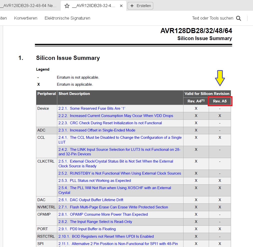
Silicon Issue Summary Tabelle AVR128DB28/32/48/64
AVR128DB28/32/48/64 Silicon Issue Summary Legend Erratum is not applicable. Erratum is applicable. Peripheral Short Description Valid for Silicon Revision Device 2.2.1. Some Reserved Fuse Bits Are '1' Rev
in „AVR128DA64 TCA1 funktioniert nicht mit alternativen Output?“ · Mikrocontroller und Digitale Elektronik · · Screenshots
-
Datei
lcd.h
to newer AVR-GCC compiler !" #endif #include <inttypes.h> #include <avr/pgmspace.h> #include "main.h" #if LCD_IO_MODE #elif defined(__AVR_AT90S4414__) || defined(__AVR_AT90S8515__) || defined(__AVR_ATmega64__) || \ defined(__AVR_ATmega8515__)|| defined(__AVR_ATmega103__) || defined(__AVR_ATmega128__) || \ defined(__AVR_ATmega161__) || defined(__AVR_ATmega162__) /* * memory mapped mode is only supported when the device has an
in „DCF auf INT0“ · Mikrocontroller und Digitale Elektronik ·
-
Datei
mw_lcd.h
to newer AVR-GCC compiler !" #endif #include <inttypes.h> #include <avr/pgmspace.h> #include "mw_main.h" #if LCD_IO_MODE #elif defined(__AVR_AT90S4414__) || defined(__AVR_AT90S8515__) || defined(__AVR_ATmega64__) || \ defined(__AVR_ATmega8515__)|| defined(__AVR_ATmega103__) || defined(__AVR_ATmega128__) || \ defined(__AVR_ATmega161__) || defined(__AVR_ATmega162__) /* * memory mapped mode is only supported when the device has an
in „DCF auf INT0“ · Mikrocontroller und Digitale Elektronik ·
-
Datei
avr_cpm.asm
<OCIE1A) sts TIMSK1,temp #endif sei .if BOOTWAIT ldi temp,10 rcall delay_ms .endif rcall printstr .db "CPM on an AVR, v1.0",13,0,0 rcall printstr .db "Initing mmc...",13,0 rcall mmcInit .if MEMTEST rcall printstr .db "Testing RAM: fill...",0,0 ;Fill RAM ldi adrl,0 ldi adrh,0 ramtestw: mov temp,adrh eor
in „CP/M auf ATmega88“ · Mikrocontroller und Digitale Elektronik ·
-
PDF
avr-gcc_14_rodata.pdf
Microchip Studio 7 Notiz für mich, Programm: Frequenzmesser mit AVR128DB48 Flags: -Os -ffunction-sections -fdata-sections -fpack-struct -fshort-enums -Wall -Wundef -c -flto -v avr-gcc binutils avrLibC zusätzliche Flags Flash RAM Bytes 7.5.0 2.40 2.1 -std=c++17 5220
in „GCC v14 Release“ · Mikrocontroller und Digitale Elektronik ·
-
Datei
avr-m8_z80.asm
2 pop temp ;2 dec temp ;1 brne bootwait1 ;2 (3*256 + 5) * 256 = 198K cycles .endif rcall printstr .db "CPM on an AVR, v1.0",13,0,0 rcall printstr .db "Initing mmc...",13,0 rcall mmcInit .if MEMTEST rcall printstr .db "Testing RAM...",13,0 ;Fill RAM ldi adrl,0 ldi adrh,0 ramtestw: mov temp,adrh eor temp
in „CP/M auf ATmega88“ · Mikrocontroller und Digitale Elektronik ·
-
Datei
avr-m8_z80.asm
2 pop temp ;2 dec temp ;1 brne bootwait1 ;2 (3*256 + 5) * 256 = 198K cycles .endif rcall printstr .db "CPM on an AVR, v1.0",13,0,0 rcall printstr .db "Initing mmc...",13,0 rcall mmcInit .if MEMTEST rcall printstr .db "Testing RAM...",13,0 ;Fill RAM ldi adrl,0 ldi adrh,0 ramtestw: mov temp,adrh eor temp
in „CP/M auf ATmega88“ · Mikrocontroller und Digitale Elektronik ·
-
Datei
z80.asm
temp,0 bootwait2: dec temp brne bootwait2 pop temp dec temp brne bootwait1 .endif rcall printstr .db "CPM on an AVR, v1.0",13,0,0 rcall printstr .db "Initing mmc...",13,0 rcall mmcInit .if MEMTEST rcall printstr .db "Testing RAM...",13,0 ;Fill RAM ldi adrl,0 ldi adrh,0 ramtestw: mov temp,adrh eor temp
in „CP/M auf ATmega88“ · Mikrocontroller und Digitale Elektronik ·
-
Datei
avr-m8_z80.asm
temp,0 bootwait2: dec temp brne bootwait2 pop temp dec temp brne bootwait1 .endif rcall printstr .db "CPM on an AVR, v1.0",13,0,0 rcall printstr .db "Initing mmc...",13,0 rcall mmcInit .if MEMTEST rcall printstr .db "Testing RAM...",13,0 ;Fill RAM ldi adrl,0 ldi adrh,0 ramtestw: mov temp,adrh eor temp
in „CP/M auf ATmega88“ · Mikrocontroller und Digitale Elektronik ·
-
Datei
lcd.h
LCD_PORT /**< port for Enable line */ #define LCD_E_PIN 6 /**< pin for Enable line */ #elif defined(__AVR_AT90S4414__) || defined(__AVR_AT90S8515__) || defined(__AVR_ATmega64__) || \ defined(__AVR_ATmega8515__)|| defined(__AVR_ATmega103__) || defined(__AVR_ATmega128__) || \ defined(__AVR_ATmega161__) ||
in „winziges Problem“ · Mikrocontroller und Digitale Elektronik ·
-
Datei
akkuload.asm
Berechnete Konstanten ; .EQU cTC1Prsc = 8 ; TC1 Vorteiler-Wert .EQU cTC1Div = fClock / cTC1Prsc / 64 ; 64 Interrupts pro Sekunde .EQU cTC1CompB = 50 ; Timer-Wert für den Start der ADC-Umwandlung .EQU cStartAdc = (1<<ADEN)|(1<<ADPS2)|(1<<ADPS1)|(1<<ADPS0); ADC Enable, Clock=128 .EQU cRestartAdc = cStartAdc
in „Asssembleprogramm für Mega16 auf Mega8535 anpassen, Sprungweite "call" und "jmp"“ · Mikrocontroller und Digitale Elektronik ·
-
Datei
akkuload.asm
Berechnete Konstanten ; .EQU cTC1Prsc = 8 ; TC1 Vorteiler-Wert .EQU cTC1Div = fClock / cTC1Prsc / 64 ; 64 Interrupts pro Sekunde .EQU cTC1CompB = 50 ; Timer-Wert für den Start der ADC-Umwandlung .EQU cStartAdc = (1<<ADEN)|(1<<ADPS2)|(1<<ADPS1)|(1<<ADPS0); ADC Enable, Clock=128 .EQU cRestartAdc = cStartAdc
in „Asssembleprogramm für Mega16 auf Mega8535 anpassen, Sprungweite "call" und "jmp"“ · Mikrocontroller und Digitale Elektronik ·
-
Datei
akkuload.asm
Berechnete Konstanten ; .EQU cTC1Prsc = 8 ; TC1 Vorteiler-Wert .EQU cTC1Div = fClock / cTC1Prsc / 64 ; 64 Interrupts pro Sekunde .EQU cTC1CompB = 50 ; Timer-Wert für den Start der ADC-Umwandlung .EQU cStartAdc = (1<<ADEN)|(1<<ADPS2)|(1<<ADPS1)|(1<<ADPS0); ADC Enable, Clock=128 .EQU cRestartAdc = cStartAdc
in „Asssembleprogramm für Mega16 auf Mega8535 anpassen, Sprungweite "call" und "jmp"“ · Mikrocontroller und Digitale Elektronik ·
-
PDF
ATMega128CAN11_short.pdf
( ( ( C ( ( T ( (NC = Do not connect (May be used in future devices) (2) Timer2 Oscillator 2 ATmega128CAN11 4251A–AVR–May 2003 ATmega128CAN11 Overview The ATmega128CAN11 is a low-power CMOS 8-bit microcontroller based on the AVR enhanced RISC architecture. By executing powerful instructions in a single
in „ATmega128CAN11“ · Mikrocontroller und Digitale Elektronik ·
-
PDF
ATMega128CAN11_short.pdf
( ( ( C ( ( T ( (NC = Do not connect (May be used in future devices) (2) Timer2 Oscillator 2 ATmega128CAN11 4251A–AVR–May 2003 ATmega128CAN11 Overview The ATmega128CAN11 is a low-power CMOS 8-bit microcontroller based on the AVR enhanced RISC architecture. By executing powerful instructions in a single
in „ATmega128CAN11“ · Mikrocontroller und Digitale Elektronik ·
-
Datei
Funktionsdec_mit_CV28_09_01_2009.asm
6125 Hz ; 0 1 1 0 CK/2 ; 0 1 1 1 CK/4 ; 1 0 0 0 CK/8 ; 1 0 0 1 CK/16 ; 1 0 1 0 CK/32 ; 1 0 1 1 CK/64(90HZ)LEXA ; 1 1 0 0 CK/128 ; 1 1 0 1 CK/256 ; 1 1 1 0 CK/512 ; 1 1 1 1 CK/1024 clr TEMP1 ; lösche TEMP1 out TCNT1,TEMP1 ; lösche Timer 1 ldi TEMP1,0b00000110 ; lösche Timer Interupts out TIFR,TEMP1 ;
in „DCC Decoder“ · Projekte & Code ·
-
Datei
Funktionsdec_mit_CV28_09_01_2009.txt
6125 Hz ; 0 1 1 0 CK/2 ; 0 1 1 1 CK/4 ; 1 0 0 0 CK/8 ; 1 0 0 1 CK/16 ; 1 0 1 0 CK/32 ; 1 0 1 1 CK/64(90HZ)LEXA ; 1 1 0 0 CK/128 ; 1 1 0 1 CK/256 ; 1 1 1 0 CK/512 ; 1 1 1 1 CK/1024 clr TEMP1 ; lösche TEMP1 out TCNT1,TEMP1 ; lösche Timer 1 ldi TEMP1,0b00000110 ; lösche Timer Interupts out TIFR,TEMP1 ;
in „DCC Decoder“ · Projekte & Code ·
-
Datei
main.cpp
PLL_fuer_Landolt.cpp * * DDS Code von S.Landolt * * Created: 12.03.2021 * Author : Devil-Elec * Code angepasst für AVR128DB48 mit TCD0 und PLL * Board: AVR128DB48 Curiosity Nano * * Ausgangspin: PA5 */ // #define TIMERTAKT_PLL // für 48MHz PLL Takt "einkommentieren" #include <avr/io.h> #include <avr/pgmspace.h> void
in „Attiny2313 Timer16 Bit, Normal Mode, unsauber“ · Mikrocontroller und Digitale Elektronik ·
-
Datei
Assembler.s
equ flashEnd = 0 .equ flashSize = 0 .equ intVectorSize = 0 .equ uartCount = 0 .equ stackEnd = 0 .equ AVR_CORE = 3 .equ AvrAccessHigh = 1 .device atmega32 .equ _CLOCK = 4000000 .equ stackSize = 128 .set FracDecimals = 7 ;avrEqus .equ bootStart = 0x0 .equ sramStart = 96 .equ sramEnd = 2143 .equ xramEnd =
in „ISR macht Newbie fertig :P“ · Mikrocontroller und Digitale Elektronik ·
-
Datei
lcd.h
LCD_PORT /**< port for Enable line */ #define LCD_E_PIN 2 /**< pin for Enable line */ #elif defined(__AVR_AT90S4414__) || defined(__AVR_AT90S8515__) || defined(__AVR_ATmega64__) || \ defined(__AVR_ATmega8515__)|| defined(__AVR_ATmega103__) || defined(__AVR_ATmega128__) || \ defined(__AVR_ATmega161__) ||
in „Display geht immernoch nicht.“ · Mikrocontroller und Digitale Elektronik ·
-
Datei
lcd.h
LCD_PORT /**< port for Enable line */ #define LCD_E_PIN 2 /**< pin for Enable line */ #elif defined(__AVR_AT90S4414__) || defined(__AVR_AT90S8515__) || defined(__AVR_ATmega64__) || \ defined(__AVR_ATmega8515__)|| defined(__AVR_ATmega103__) || defined(__AVR_ATmega128__) || \ defined(__AVR_ATmega161__) ||
in „LCD von Peter Fleury“ · Mikrocontroller und Digitale Elektronik ·
-
PDF
kicad_8450_dcm_liste_neu_v3.pdf
, JTAG ATXMEGA128A3-MH QFN64, 128k Flash, 8k Boot, 8k SRAM, 2k EEPROM, JTAG ATXMEGA128A3U-AU TQFP64, 128k Flash, 8k Boot, 8k SRAM, 2k EEPROM, JTAG, USB ATXMEGA128A3U-MH QFN64, 128k Flash, 8k Boot, 8k SRAM, 2k EEPROM,
in „KiCAD Eeschema, Bibliotheksdokumentation *.dcm als PDF-Datei“ · Platinen ·
-
Datei
lcd.h
LCD_PORT /**< port for Enable line */ #define LCD_E_PIN 6 /**< pin for Enable line */ #elif defined(__AVR_AT90S4414__) || defined(__AVR_AT90S8515__) || defined(__AVR_ATmega64__) || \ defined(__AVR_ATmega8515__)|| defined(__AVR_ATmega103__) || defined(__AVR_ATmega128__) || \ defined(__AVR_ATmega161__) ||
in „LCD Problem“ · Mikrocontroller und Digitale Elektronik ·
-
Datei
lcd.h
LCD_PORT /**< port for Enable line */ #define LCD_E_PIN 6 /**< pin for Enable line */ #elif defined(__AVR_AT90S4414__) || defined(__AVR_AT90S8515__) || defined(__AVR_ATmega64__) || \ defined(__AVR_ATmega8515__)|| defined(__AVR_ATmega103__) || defined(__AVR_ATmega128__) || \ defined(__AVR_ATmega161__) ||
in „LCD Atmega8535 fehler beim Programm erstellen mit AVR-Studio“ · Mikrocontroller und Digitale Elektronik ·
-
Datei
lcd.h
PORTC /**< port for Enable line */ #define LCD_E_PIN 1 /**< pin for Enable line */ #elif defined(__AVR_AT90S4414__) || defined(__AVR_AT90S8515__) || defined(__AVR_ATmega64__) || \ defined(__AVR_ATmega8515__)|| defined(__AVR_ATmega103__) || defined(__AVR_ATmega128__) || \ defined(__AVR_ATmega161__) ||
in „Funktion wird nicht ausgeführt mit Ausgabe auf LCD“ · Mikrocontroller und Digitale Elektronik ·
-
Datei
main.asm
Branch according to NVM version: cpi tmp0, '0' breq loop_readByte_nvm0 ; NVM version number != 0, e.g. AVR_DB and AVR_DD. ; These devices apparently need a more complicated procedure: rcall applyReset rcall updi_idle rcall updi_wait25ms rcall releaseReset rcall updi_idle rcall updi_wait25ms rcall sendNvmProgKey
in „AVR64DD28, mEDBG, Studio 7.0 - Fehler beim Schreiben von Fuses“ · Mikrocontroller und Digitale Elektronik ·
-
 Bild
Bild
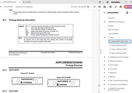
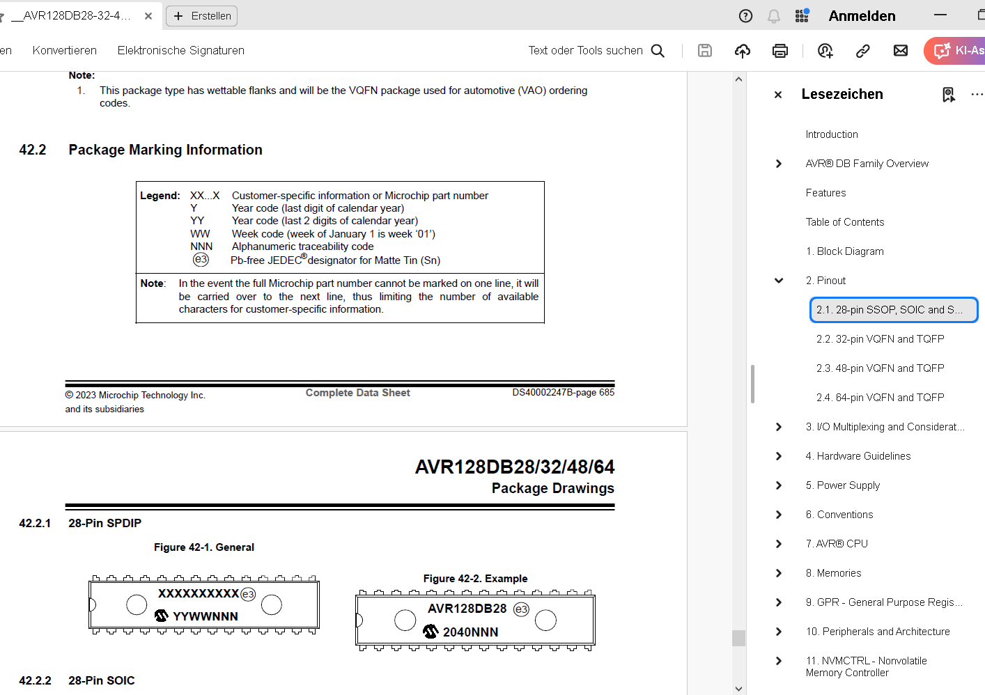
Datenblatt Ausschnitt AVR128DB Package Marking Information
information. © 2023 Microchip Technology Inc. and its subsidiaries Complete Data Sheet DS40002247B-page 685 AVR128DB28/32/48/64 Package Drawings 42.2.1 28-Pin SPDIP Figure 42-1. General XXXXXXXXXX e3 Y YWWNNN Figure 42-2. Example AVR128DB e3 2040NNN 42.2.2 28-Pin SOIC
in „AVR128DA64 TCA1 funktioniert nicht mit alternativen Output?“ · Mikrocontroller und Digitale Elektronik · · Screenshots