Nächste Käsescheibe: Die Led-Stränge werden mit BD135 geschaltet, Basis über 4k7 an + Die Basis wird mit 74HC05 auf GND gezogen. Was ich jetzt nicht verstehe: Die restliche Elektronik bekommt 5V aus + durch einen 7805. Die HC05 bekommen ihre eigene
Wirklichkeit anders und/oder ist ein > Darlingtontyp. Er hatte in einem oberen Post schon was von einem BD135 geschrieben. Könnte bei der Sauklaue auch stimmen.
H2 I H 1 L 0 - 40 0 55 85 125 150 P d Tamb(°C) Note • Zero power is considered as measuring power max. 1 % of max. power. PHYSICAL DIMENSIONS FOR RELEVANT TYPE (all dimensions in millimeters) H1 R25VALUE BMAX. d H2 MAX. L P T MAX. MIN. MAX. 3.3 to 220 5.0 0.6 ± 0.06 1.0 4.0 6.0 24 ± 1.5 2.54 4.0
NAL 2) anlegen. 1-13 Inbettri bnahme D rchführen von M sungen ngen CHANNEL1 Al C Damae Lvl: V OsMAX.502 CHAWJEL2 <θ√ Z ≡C≥k rh Ö: Damags Lvi: 5Vrms MAX.502 M/ Freq & MΓ Ď / Ratio E R E G U E ⁄√L I Freq Chl U Freq & ZI Ratio F RFreq G U E N E Ch 2 I πππr ~ιπ π π π π ππ I LJ-LILIL Ju u d L iu L Ju Freq
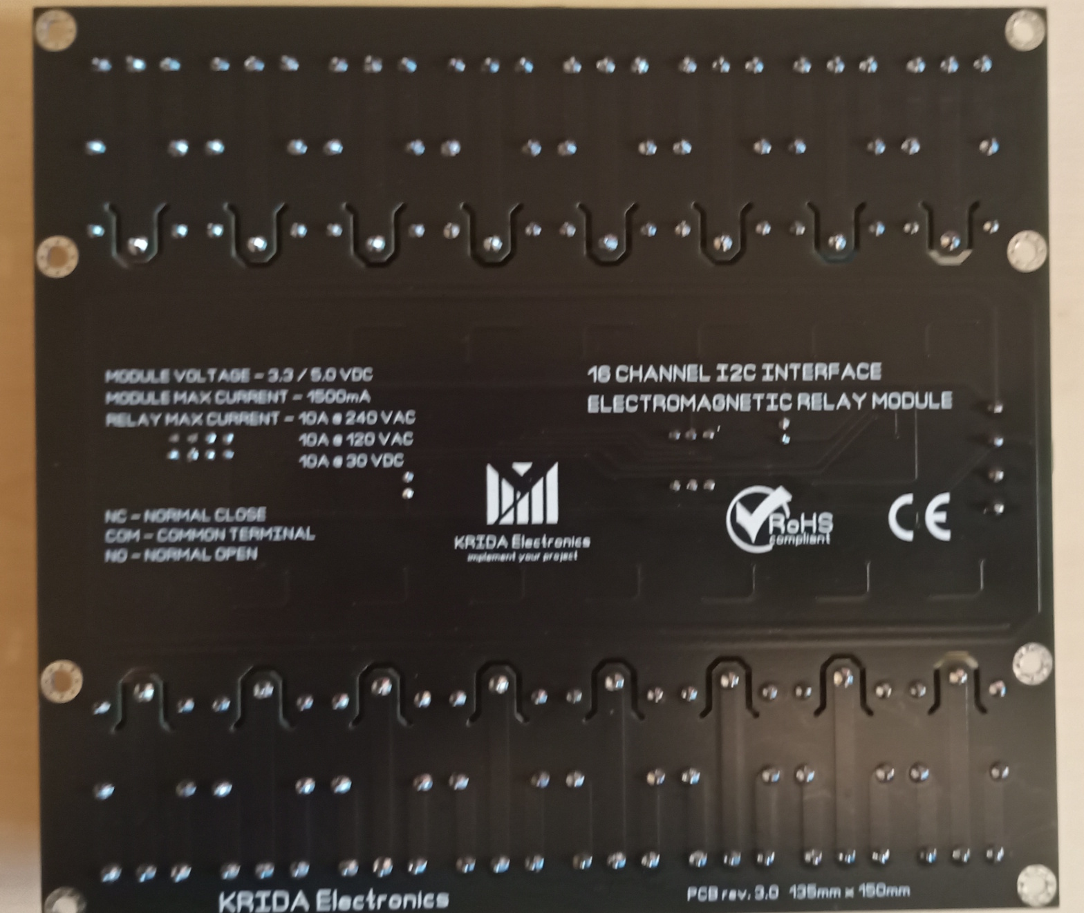
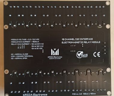
channel-i2c-electromagnetic-relay-module-iot/#product-description Daraus: PCB board dimension 135mm x 150mm Operation DC voltage – 3.3V and 5.0V Maximum current @5.0V – 1500mA<br> Maximum current per relay – 5A...10A @ different voltages LEDs indicators for each electromagnetic relay
switch contacts: Normally Open, Common, Normally Closed Relay contact resistance 100 milliohms max. ( initial value ) Relay insulation resistance 100 MOhm min. (DC 500V) Relay operation time 8 ms max Relay release time 5ms max Relay dielectric strength 750 VAC, 50/60Hz between contact
MODULE VOLTAGE - 3.3 / 5.0 VDC
MODULE MAX CURRENT - 1500mA
RELAY MAX CURRENT - 10A <=> 240 VAC
10A <=> 120 VAC
10A <=> 30 VDC
NC - NORMAL CLOSE
COM - COMMON TERMINAL
NO - NORMAL OPEN
16 CHANNEL I2C INTERFACE
ELECTROMAGNETIC RELAY MODULE
KRIDA Electronics
implement your project
RoHS compliant
CE
KRIDA Electronics
PCB rev. 3.0 135mm x 150mm
between pins TX1 and TX2 at 13.56 MHz. [7] DD(SVDD)depends on the load at pin MFOUT. Vmod V V i(p-p)(max) i(p-p)(min) VMID 13.56 MHz carrier 0 V 001aak012 Fig 24. Pin RX input voltage range 14.1 Timing characteristics Table 154. SPI timing characteristics Symbol Parameter Conditions Min Typ Max Unit WL
Main Specifications of the TODX283 Data rate: DC to 50 Mb/s (NRZ code) Transmission distance: 10 m (max) (via APF cable) 100 m (max) (via PCF cable) Pulse width distortion: less than ±7 ns Center wavelength: 650nm Operating temperature: –10°C to 70°C TTL interface TODX283 7 OpticalM odulesforHigh-SpeedDataT
substitute(messmode=self._function) for key, cmd in self._syntax_table.items() } # mit Formatierung max_key_len = max(len(key) for key in modified_list.keys()) for key, cmd in modified_list.items(): print(f"{key:<{max_key_len}} {cmd}") return syntax except KeyError: return f'command unknown → {name}'
Output Current 3 Imax A VI–VO 15 V, PD P max,T Package 1.5 2.2 – VI–VO= 40 V, PD P max, A = +25⋅C, T Package 0.15 0.4 – RMS Noise, % of VO, TA= +25⋅C, 10 Hz f 10 kHz N – 0.003 – % V O Ripple Rejection,OV = 10 V, f = 120 Hz (Note 4) 4 RR dB
H2 I H 1 L 0 - 40 0 55 85 125 150 P d Tamb(°C) Note • Zero power is considered as measuring power max. 1 % of max. power. PHYSICAL DIMENSIONS FOR RELEVANT TYPE (all dimensions in millimeters) H1 R25VALUE BMAX. d H2 MAX. L P T MAX. MIN. MAX. 3.3 to 220 5.0 0.6 ± 0.06 1.0 4.0 6.0 24 ± 1.5 2.54 4.0
7.1 9 S H Stall current Anlaufstrom I/I A 2.7 1.5 S H Performancecharacteristics* Leistungsdaten* max. Output power max. Abgabeleistung Pmax W 7.0 7.0 max. Constant torque max. Dauerdrehmoment Tmax/M max Ncm 1.1 1.1 Motor parameters* Motorparameter* Weight Gewicht G g 135 135 2 Rotor inertia Läuferträgheitsmoment
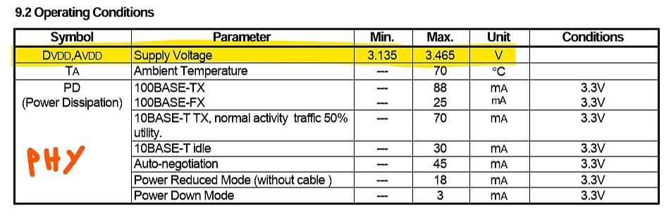
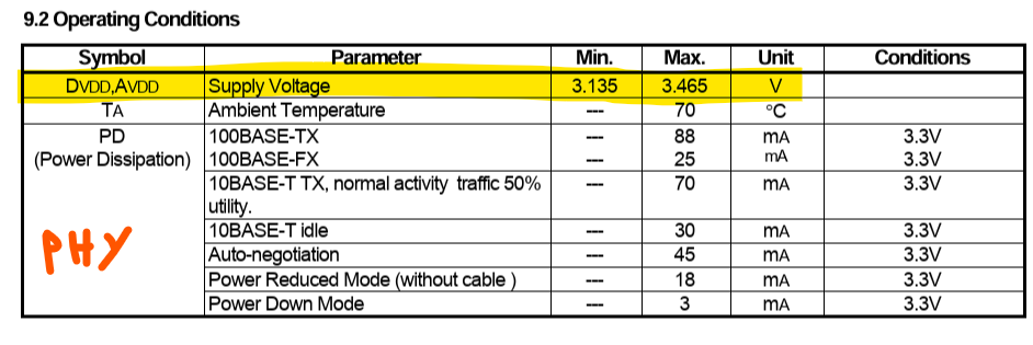
9.2 Operating Conditions
Symbol Parameter Min. Max. Unit Conditions
DVDD,AVDD Supply Voltage 3.135 3.465 V
TA Ambient Temperature --- 70 °C
PD (Power Dissipation) 100BASE-TX --- 88 mA 3.3V
100BASE-FX --- 25 mA 3.3V
10BASE-T TX, normal activity traffic
L, Soldering, 10 sec.) --- 260 °C 9.2OperatingConditions Symbol Parameter Min. Max. Unit Conditions D VDD,AVDD SupplyVoltage 3.135 3.465 V TA AmbientTemperature --- 70 °C PD 100BASE-TX --- 88 m A 3.3V (PowerDissipation) 100BASE-FX --- 25 mA 3.3V 10BASE-TTX,normalactivity traffic50%
Kleines Update: Der Streifen mit der Beschriftung max. 33 V DC funktioniert. Einen anderen baugleichen teste ich morgen. Der Streifen, den ich anfangs fotografiert habe bleibt jedoch dunkel. Habt ihr noch eine Idee, was ich da prüfen könnte? Ich bin
www.ledhilfe.de/viewtopic.php?t=5556 Die andere Lösung verwendet einen Stromspiegel aus zwei Transistoren (BD135, BD136, usw.). https://www.ledstyles.de/index.php?thread/9336-symmetrierung-paralleler-leds-mittels-stromspiegel/
portEthernetSwitchControllerwithMII/RMIIInterface 7.2.6 Per Port Bandwidth Control Register (115h, 135h, 155h) PHY_ADR REG_ADR ABS_ADR 08h,09h,0Ah 15h 115h,135h,155h Bit ROM Type Default Description 15:12 84h.[15:12] PSE,RW 0000b INGRESS[3:0] 94h.[15:12] Ingress Rate Control (Separated mode) A4h.[15:
than 10µV, zero drift of less than 1µV/°C, • On-chip clock and reference input bias current of 10pA (max) and rollover error of less than one count. True differential inputs and reference are useful in • Low power dissipation - typically less than 10mW all systems, but give the designer an uncommon advantage
Digitalpotis gedacht, jedoch sind diese > Wahrscheinlich nicht genau genug, da die Tankanzeige einen max. R von > 470 Ohm und die Temp. Anzeige von 6k Ohm benötigt. Ich kenne nichts ungenaueres als übliche Tankanzeigen.
Vadim schrieb im Beitrag #7987818: > Tankanzeige einen max. R von 470 Ohm und die Temp. Anzeige von 6k Vorausgesetzt, die Anzeigen zeigen max/min mit 470R/0R und 6k/0k, bitte ich um folgende DC-Messwerte: Tank Umax: Spannung am 470R (also Tankanzeige Vollausschlag
graph, a bar graph, or a spectrogram. Averaging is available (exponential averaging, min hold, and max hold) in the jitter spectrum display. Averaging is not available in the other displays. EnhancedStimuli Within this application, the DIT menu choices provide extra features for controlling the digital
cigarette-box-dimensions-sizes/?is_otto_page_fetch=1&otto_block_title=0&otto_block_desc=0 Na 23x80x135mm und Ausgangsspannung passen aber überhaupt nicht zu den verlangten Forderungen. Die Forderungen erscheinen mir nicht ausgegoren zu sein.
Wolf17 schrieb im Beitrag #7979289: > -Ausgangsstrom? max 300mA > -Eingangsspannung? laden an USB-Netzteil (USB-C?) bzw. 12V Bordnetz mit Adapter wäre wohl das Einfachste > -gewünschte Wh? 10...12h x 300mA = max 3,6 Ah > -Umgebungsbedingungen
, F is the Acknowledge. The master then sends the higher data byte to be IN,MAX SW written into the desired register. The ISL88731 will respond with switching frequency and I L,MAX is the max DC current in the an Acknowledge. The master then issues a Stop condition, inductor. indicating to the ISL88731 that the current transaction is For VIN,MAX = 20V, VBAT = 12.6V, IBAT,MAX = 4.5A, and complete. Once this transaction completes the ISL88731 will fs= 400kHz, the calculated inductance is 9.3µH. Choosing the begin operating at the new current
hier nicht weiter > schwierig. Das erste Bild um 90° gegen den Uhrzeiger gedreht liest man > "FYD135C08AR1". Diese Bezeichnung google vorgeworfen findet so einiges. > > Der ganze thread ist ein beispiel wie manche in der Tuner-Szene ticken: > Nimm einen x-beliebigen Moter und schraub an dem rum
Max I. schrieb im Beitrag #7970405: > Josef schrieb im Beitrag #7970111: >> demnächst im Studium > > Entsetzlich, was heutzutage alles studieren darf. @Max I. Dein Kommentar zeigt leider genau
dissipation ratings are measured under board mounted and still air conditions. Symbol Definition Min. Max. Units VB High side floating supply voltage -0.3 625 VS High side floating supply offset voltage VB- 25 VB+ 0.3 V High side floating output voltage V - 0.3 V + 0.3 V HO S B VLO Low side output voltage
Kupfer nicht einfach ins Klo schicken) ist mir zu aufwaendig. Und das ein Dia-Film (Ektachrome E100, 135-36) jetzt freundliche 29EUR (!) kostet, ist auch nicht hilfreich.
Zahnmedizin wird H2O2 als dreiprozentige wässrige Lösung zur lokalen Desinfektion... "Produkte mit max. 79 g/kg (<8%) sind frei verkäuflich. Ab 80 g/kg gilt die Lösung als Gefahrstoff." also früher(TM) gab es bis 33% in der Drogerie, wenn ich mich recht erinnere.
. 28 mm Bandbreite: min. 10 mm max. 400 mm Strip width: min. 10 mm max. 400 mm AnzahStreifenlänge: enen Lmin. 20 mm ser: max. 3000 mmmax. 3 NumbStrip length: t diamemin. 20 mm max. 3000 mm max. 3 Materialstärke 0,27 / 0,30 / 0,35 / 0,50
Antworten. Ich habe jetzt mal 5 Potis in Mittelstellung durchgemessen. Zwischen den beiden Werten sind max. 2 kilo-Ohm Unterschied. Ich messe morgen alle mal durch.
> Ich habe jetzt mal 5 Potis in Mittelstellung durchgemessen. > Zwischen den beiden Werten sind max. 2 kilo-Ohm Unterschied. Du wirst nicht genau die Mittelstellung getroffen haben. Die Potis sind definitiv linear.
Hercules-Karte > unterstützte. Microsofts Codeview kann das auch. Und sicher einiges andere mehr. Max I. schrieb im Beitrag #7963593: > Cartman E. schrieb im Beitrag #7962864: >> 486 können ISA, VLB, EISA und Microchannel. > > Und PCI. Hmm. Mit PCI war der "Pentibumm" schon greifbar. 486er
ressourcenschonender. Mittlerweile erlebt Raytracing wieder ein Comeback, da wo es auf Präzision ankommt. Max I. schrieb im Beitrag #7963593: > Cartman E. schrieb im Beitrag #7962864: >> 486 können ISA, VLB, EISA und Microchannel. > > Und PCI. Wer einen 486er haben will und noch keinen hat, der holt
and V ds being the intrinsic drain-source voltage. The charge and capacitances are: for V > V new max 168 V max Vnew − V max Q gs = Cgs0· 2·Vbi 1 − 1 − + (11.364) V bi 1 − VVax bi ∂Q gs C gs0 ∂Vnew = · (11.365) ∂Vgs 1 − VVax ∂V gs bi ∂Q gs C gs0 ∂Vnew = · (11.366) ∂Vgd 1 − VVax ∂V gd bi and
Selbsttestfunktionen - unter anderem die hohe Zertifikation und die Fähigkeit des Chips aus, bis zu 135 Grad Celsius zu ertragen: [c] Built-in functional safety with on-going TÜV-certification* for SIL 2 hardware integrity and systematic SIL 3 capability, with safety development packages • Extended reliability with qualification up to 135 °C and a 10-year mission profile at 105 °C [/c] ### Analog Devices ADHV4710 - Operationsverstärker mit 1 A Ausgangsstrom und +/- 55 V-Fähigkeit. Dass Operationsverstärker nützlich sind, steht außer
asiatischen Händlern erhalten kann. Elektor definierte folgende Mindestanforderungen an TUN: U CEO / V I C max. / A h FE ( ) P max. / W f T / MHz 20 0,1 100 0,1 100 Das sind keine hohen Anforderungen. Gehäuseform und Anschlussbelegung wurden nicht definiert. Als Beispiele für TUN gab Elektor folgende Typen an
ULN2801 ULN2802 ULN2803 ULN2804 DIL18 SO18 50 0,35 1 kHz 8x Low-Side NPN-Darlington, Freilaufdiode, max 500mA insgesamt Rei, Far, alle alldatasheet.com 0,35 - 0,50 UDN2981 DIL18 SO18 50 0,35 1 kHz 8x High-Side NPN-Darlington, Freilaufdiode, max 500mA insgesamt, obsolete, Ersatz: Micrel MIC2981 Rei, Far
The thermistor is used to Table 2. NTC THRMISTOR SPECIFICATION Parameter Symbol Condition Min. Typ. Max. Unit Resistance R 25 TC= 25°C 99 100 101 kW Resistance R100 TC= 100°C 5.18 5.41 5.60 kW Temperature Range −40 +125 °C ] [ e l V e n t s e r t i r h T Case Temperature [5C] Figure 8. NTC Thermistor
1200 l/h, was für Hubschrauber waren das? CH-47 Chinook? Ein üblicher Polizeihubschrauber (z.B. EC135) verbraucht vielleicht 1/5 davon.
h (durchschnittlich) Da fliegt diese aber in diesem Rahmen: Marschgeschwindigkeit, 215 km/h; max. 240 km/h ; Kannst ja mal hochrechnen, was dafür gebraucht würde: Höchstgeschwindigkeit, 295 km/h (VNE) ;
key. Normal value INVALID ITEM P1-4 TMP1: 111 to 255 OUTLVL: 255 P2-1 P1-8. HDMITHM 1:DC 255 TMP2: 135 to 255 P1-5. LIMITER CONTROL Not for service. (Reference voltage: 3.3 V=255) Power limiter control is detected. P2-2 * If TMP1 or TMP2 becomes out of the normal P1-8 2.NoPRT (Reference voltage: 3.3
check the log afterwards and check for duplicate barcodes.\r\nThe function cannot be undone. Strings.135=Do you really want to do this? Strings.136=New data translation Strings.137=Enter the Description: Strings.138=Edit Data Translation Strings.139=Enter the Description: Strings.140=Do you really want

 Bild
Bild
 Bild
Bild
 Bild
Bild