(ground = 0 V). Symbol Parameter Conditions 25 °C -40 °C to +85 °C -40 °C to +125 °C Unit Min Typ Max Min Max Min Max V HIGH-level V = 4.5 V to 5.5 V 2.0 1.6 - 2.0 - 2.0 - V IH CC input voltage V LOW-level V = 4.5 V to 5.5 V - 1.2 0.8 - 0.8 - 0.8 V IL CC input voltage V HIGH-level V = V or V ; V = 4.5
specified. Table 4 DC Characteristics Parameter Symbol Values Unit Note / Test Condition Min. Typ. Max. Operating supply voltage V 4.5 – 60 V – S Operating bias control voltage VB 4.5 – V V recommended to S connect toV S Under Voltage Lock Out V 4.05 4.25 4.45 V IC deactivated1) S, UV, off VS, UV, on
Normale Verschleißteile sind kaum ein Problem. Wenn sich die Schrauben lösen lassen, ist eine Achse in max. 3h mit neuen Bremsteilen (Scheiben und Beläge) neu bestückt. Voraussetzung ist natürlich eine ausreichend geräumige Garage. Im Freien bei Regen oder Schnee möchte ich das auch nicht machen wollen!
noch nie gedacht. Da gibts so nen Witz, kommt ne Frau zur Werkstatt und sagt das an ihrem Auto das 710 weg ist, Kopfkratzen in der Werkstatt, bis die Frau auf das Teil in einem anderem Auto zeigt https://etel-tuning.eu/wp-content/uploads/2014/10/710_2.jpg Zurück zum Thema ich hatte mal einen Astra
PC-Relaiskarte K8 IO Best.Nr. 710 722 V 1.3 Pollin Electronic GmbH •Tel. (08403) 920-920 • www.pollin.de Stand 15.12.2008, online, #all, hka Wichtiger Hinweis! Lesen Sie diese Gebrauchsanleitung, bevor Sie die Relaiskarte in Betrieb
notebook computers. 1,2,3 ; Source 4 ; Gate 5,6,7,8 Drain FEATURES • Low on-resistance R DS(on)= 10.5 m MAX. (V GS = 10 V, I = 5.0 A) 6.0 ±0.3 1 4 R DS(on)= 14.0 m MAX. (V GS = 4.5 V, I = 5.0 A) 4 5.37 MAX. 4.4 0.8 . 1 R DS(on)= 17.0 m MAX. (V GS = 4.0 V, D = 5.0 A) X . . iss iss M + – • Low C : C = 2200
θ A c A D D1 E b1 L b e e1 TO-94 package mechanical data dimensions symbol millimeters inches min max min max A 1.520 1.720 0.059 0.067 A1 0.700 0.900 0.028 0.035 A2 0.500 0.700 0.020 0.028 b 0.360 0.500 0.014 0.020 b1 0.380 0.550 0.015 0.022 C 0.360 0.510 0.014 0.020 D 4.980 5.280 0.196 0.208 D1 3.780
den Nennvolumenstrom. Folgende Richtwerte sollten dabei nicht überschritten werden: dp = 120 Pa/m max von Rohrleitungen DN 10 bis DN 65 w max = 0,7 m/s von Rohrleitungen DN 80 bis DN 125 w max = 1,2 m/s ab Rohrleitungen DN 150 w = 2,0 m/s max Subject to change and error 20/327 Version 11/2021 Abb. 0.8
"Class D", da die ein Stromfresser sind. "Class A" hat bei Vollaussteuerung einen Wirkungsgrad von max 50%, d.h. ein 2 * 50W Verstärker muß in Ruhe 200W verheizen. Im HiFi-Bereich findet man daher oft "Class AB". In alten Röhrenradios war noch "Class A" gebräuchlich. Für max 6W am Lautsprecher verheizte
damit die Spannung am Ausgang nicht zu hoch wird? „Hat man zu wenig Spannung, bezieht der ICL710x seine Vergleichswerte nicht mehr aus der stabilen Zenerspannung, sondern der absackenden Betriebsspannung und misst falsch. Er funktioniert aber scheinbar noch. Man kann den Chip aber auch an 5V
kann das Ganze doch nicht sein, oder? [pre] +5V ---+---------+ | | 74LVC1G86 MAX809-5-----|\ | |X)-- LoBat Segment | BP---|/ | | GND ---+---------+-- TEST [/pre]
” The minimum bootstrap capacitor value can be calculated from the following equation: 2 2 Q + Iqb(max)+Q +ls ICb( le)k ⎢ f f ⎥ C ≥ ⎣ ⎦ Vcc− V f− V LS−V Min where: Q g Gate charge of high-side FET f = frequency of operation ICbs (leak)ootstrap capacitor leakage current Iqbs (max)Maximum V BS quiescent
place.The compressors will withstand storage temperatures down to -35°C. Condensing temperatures: Max. 60°C at stable conditions and max. 70°C at peak load. Ambient temperatures: Min. -10°C, max. 55°C The BD compressor concept includes an electronic unit which features overload protection, battery protection
AAA Energizer Max (Singapore) AAA Energizer Max aus IR-FB gebr. MHD 12-2030 MHD 12-2030 Kauf 10-2020 Kauf 10-2020 17. Oktober 2021 15. Mai 2024 Entladung mit: 30 mA Entladung mit: 30 mA mAh max: 1197 mAh max: 1100 Time
zusammenhängt, Energiekosten, Batterielaufzeit, Erwärmung etc. Aber halt nicht für die Messschaltung. Die max. Angabe bei mV/V kommen daher das die Widerstände nur eine endliche Belastung haben bei der dieses gut funktionieren. Überschreitet man diese Grenze wird das ganze möglicherweise ungenau weil sich alles
Angeboten dieser Anzeigemodule ist vom HX711 die Rede, aber auf der Rückseite glaube ich "nur" einen HX710B zu sehen. Wie schon erwähnt, das Teil ist noch nicht angekommen, ich habe nur die Bilder der Anbieter.
(unless otherwise noted) DD PARAMETER TEST CONDITIONS † TLC252_C TLC25L2_C TLC25M2_C UNIT MIN TYP MAX MIN TYP MAX MIN TYP MAX 25°C 10 10 10 TLC25_2C 0°C to 12 12 12 70°C 25°C 5 5 5 Input VO = 0.2 , VIO offset TLC25_2AC R = 50 Ω 0°C to mV voltage S 70°C 6.5 6.5 6.5 25°C 2 2 2 TLC25_2BC 0°C to 3 3 3 70
Depth : 237 mm (9.33'') SOG (Sync On Green) Height : 428 mm (16.85'') -Min Digital 508 mm (19.99'') -Max 3-2. Video Input Signal 1) Type : R, G, B Analog 7. WEIGHT (with SPEAKER) 2) Voltage Level : 0~0.71 V Net. Weight : 8.8kg (19.40 lbs) a) Color 0, 0 : 0 Vp-p Gross Weight : 11.3kg (24.91 lbs) b) Color
I2C0 n High-Performance 32 o Crossbar Switch l r 32 I2C1 e h 32 32 32 32 r e 32 RT1 P I/O Interrupts MAX0 CONTROL MAX1 Events 32 PLL Out in EMIF dMAX Peripheral Interrupt and DMA Events 64 RX-V667/HTR-6063/RX-A700 Function Name No. TYPE (1)PULL (2) GPIO (3) Detail of Function X (P.C.B.) V R 6 1 VSS - /
Soldering, 10 sec.) 260˚C Input Voltage ± 7V Electrical Characteristics (Note 3) Parameter Conditions LM710 LM710C Units Min Typ Max Min Typ Max Input Offset Voltage R S 200 , V CM = 0V, TA = 25˚C 0.6 2.0 1.6 5.0 mV Input Offset Current V =1.4V, T = 25˚C 0.75 3.0 1.8 5.0 µA OUT A Input Bias Current TA = 25
automatisch noch manuell. Überprüft habe ich als erstes das Piher-Poti VR400, dann die Spannungen am LM710 (IC400) und die 5V von IC600. Da messe ich allerdings nur 4,9V. Das scheint mir für einen 78L05 etwas viel Abweichung. Deshalb fallen mir gleich noch C512 und C602 ein. Leider kommt man da nicht so
bin, ob der BF450, den ich nur hatte, in der Schaltung funktioniert. Der hat außerdem eine geringere max. Verlustleistung.
großenAuflösung bleibt die dieAlias-Effektevermeidet? Schwankung ohneAuswirkung. A knapp über 2 ⋅ max D DasAbtastergebnis wirdverbessert (Dithering). B knapp über 𝑓 max C knapp unter 𝑓max AF622 Welcher Filtertyp ist geeignet,umAlias- 2 Effekte zuvermeiden,und wo ist das Filter D knapp unter 𝑓 max
frames to completely transfer the data. Reception of a data packet that is less than the endpoint’s Max Packet size during Control, Bulk or Interrupt transfers signals the completion of the transfer set, even if there are active TDs remaining for this transfer set. Setting the SPD bit in a TD indicates
25s(typ.) for 32Mb, and 50s(typ.) for 64Mb • Low Power Consumption - Low active read current: 25mA(max.) at 86MHz, 20mA(max.) at 66MHz and 10mA(max.) at 33MHz - Low active programming current: 20mA (max.) - Low active erase current: 20mA (max.) - Low standby current: 20uA (max.) - Deep power-down mode
Synonym of the Current Language key. Load Balance Timeout Synonym of the Connection Lifetime key. Max Pool Size The maximum number of connections that are allowed in the pool. Max Pool Size does not impose any restrictions other than those implied or explicitly stated in this section. Examples of such
Herstellerwebseite ist es aber 'Blaues Terahertz-Licht', also eher 420 - 490nm damit irgendwo bei 610-710 THz. Da sollte das Auge ein guter Detektor sein, kein blaues Leuchten, keine Teraherz.
heilt es. Das Marketing und die "community" ist reiner > Bullshit. Also das blaue Licht kann nur max. 1mm in den Körper eindringen, gibt genug Untersuchungen dazu (zur Eindringtiefe von Licht), somit muss noch eine 3. Funktion verbaut sein, sonst klappt das nicht mit den 200 bis 300mm Eindringtiefe
HauptleitungsschutzschalterE 35 A ja +A0-F1 2,27 kA 1,55 kA Zweig +A1-F2 Leitungsschutzschalter C 32 A ja +A1-F1 2,24 kA 710 A Zweig +A2-F1 Fehlerstromschutzschalter 40 A / 30 mA (Typ=A) - - 1,52 kA 693 A Zweig +A2-F2 Leitungsschutzschalter C 16 A nein +A1-F2 878 A 356 A Zweig +A2-F3 Leitungsschutzschalter C 16 A nein +A1
werden, bei dem das Schirmpotenzial durchgeführt wird, z.B. DSUB9-Stecker von ERNI (ERBIC CAN BUS MAX, Bestell-Nr.:154039). • Ist eine gemischte Verwendung von zwei- und vieradrig verdrillten Leitungen nicht zu vermeiden, ist auf eine durchgehende CAN-GND-Verbindung zu achten! • Abweichungen von der
Pout is 200W The typical junction-to-case thermal resistance of (MusicPower). the TDA7294S is 1 oC/W (max=1.5 C/W). To avoid that, in worst case conditions, the chip temperature exceedes 150 oC, the thermal resis- APPLICATION NOTE: (ref. fig.7) tance of the heatsink must be 0.038 C/W (@ max ambient temperature
or 5V ² 10%; V PP = VCC ) M27C1001 Unit Symbol Alt Parameter Test Condition -35 (3) -45 -60 -70 Min Max Min Max Min Max Min Max AVQV tACC Address Valid to E = VIL G = VIL 35 45 60 70 ns Output Valid tELQV CE Chip Enable Low to G = VIL 35 45 60 70 ns Output Valid GLQV OE Output Enable Low E = VIL 25 25
Verkaufe gebrauchten Testserver, ist in Summe max. 1 Monat gelaufen, Zustand sehr gut. Der SR-650 hat noch Herstellergarantie bis 17.09.2023. Foto 1 ist ein anderer Server, kann aber leider nicht gelöscht werden! Details zum SR-650: - ThinkSystem
%+.5f]\n", min (min (spline.y0, spline.y1), min (spline.y2, spline.y3)), max (max (spline.y0, spline.y1), max (spline.y2, spline.y3))); for (int i = 0; i <= n; ++i) { double t = (double) i / n; double y = eval (&spline, t); double x = mix
Die Köningin der Approximation durch Polynome (oder rationale Funktionen) ist naturlich die MiniMax-optimierte Approximation, d.h. diese erfüllt nachweislich [math] \max_{x\in[a,b]} |f(x)-g(x)| \stackrel!= \min [/math] und ist in diesem Sinne optimal. Wermutstropfen ist dabei lediglich, dass
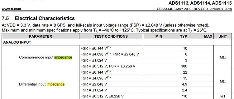
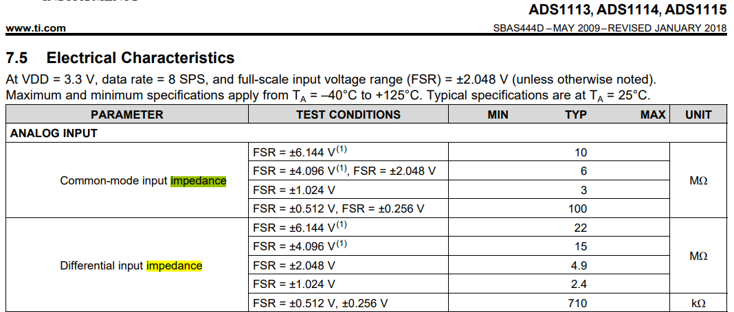
from TA = -40°C to +125°C. Typical specifications are at TA = 25°C.
PARAMETER TEST CONDITIONS MIN TYP MAX UNIT
ANALOG INPUT
FSR = ±6.144 V(1) 10
Common-mode input impedance FSR = ±4.096 V(1), FSR = ±2.048 V 6 MΩ
FSR = ±1.024 V 3
FSR = ±0.512 V, FSR = ±0.256 V 100
Differential input impedance FSR = ±6.144 V(1) 22
FSR = ±4.096 V(1) 15 MΩ
FSR = ±2.048 V 4.9
FSR = ±1.024 V 2.4
FSR = ±0.512 V, ±0.256 V 710 kΩ
the maximum speed, we need to define the acceleration/deceleration. For this we use the function setMaxSpeed() and setAcceleration() . void setup() { // Set the maximum speed and acceleration: stepper.setMaxSpeed(1000); stepper.setAcceleration(500); } In the loop section of the code, we let the motor

 Bild
Bild