-
PDF
max774-max776.pdf
High-Efficiency, Low I Inverting DC-to-DC Controllers Q 6 VIN VIN 7 1 5 7 1 OUT V+ 5 OUT V+ C1 C2 R1 R2 R3 X 150µF 0.1F 0.07 3 MAX774 0.07Ω A 3 MAX774 6 SHDN 6 SHDN MAX775 CS Q1 C1 C2 2 MAX775 CS Q1 2 MAX776 7 Si9435 150µF 0.1F FB MAX776 7 Si9435 / FB EXT P R1 EXT P VOUT 4 VOUT 4 5 REF GND REF GND 1N5822/ 7 L1 1N5822/ C4* C3 8 L1 MBR340 7 C3 8 22µH MBR340 0.1F 22 H 0.1 F C4* X *MAX774 = 33µ F, 10V *MAX774 = 33µF, 10V A MAX775, MAX776 = 120F, 20V MAX775, MAX776 = 120F, 20V M OUTPUT INPUT OUTPUT Figure 4. Nonbootstrapped Operation
in „[V] kleines Konvolut ältere DIL / DIP ICs (8€)“ · Markt ·
-
PDF
icecubev1.2-sch.pdf
JP3 1 FUSETE5D1 1N5817 T 1 1N5817 V LED_R 1 2 SWITCH1 +9V- GND A R 27 L1 LED_G 3 4 SWITCH2 2 F B C F MBR160 e6 C5 k LED_B 5 6 SWITCH3 C1 C2 V 7 0 e 1 0 R14 7 8 R15 DCF / C4 C3 F 4 1 100V/33 F 0.1uF R 1 9 10 0.1uF 2 1 GND GND 2 D 5 0 VCC 150 150 10uF/25V 2 0 Q F D 6 GND BOOST I GND GND GND GND GND GND C
in „Röhrenuhr IV-18“ · Projekte & Code ·
-
PDF
_LM2678.pdf
C6 33 16 0.96 1000 16 1.3 3300 10 2.18 820 35 1.62 C7 100 16 1.92 150 35 0.65 3900 10 2.36 1000 35 1.73 C8 150 16 2.28 470 35 1.3 6800 10 2.68 2200 35 2.8 C9 100 20 2.25 680 35 1.4 180 16 0.41 56 50 0.36 C10 47 25 2.09 1000 35 1.7 270 16 0.55 100 50 0.5 C11 220 63 0.76
in „Schaltregler - starke Lastschwankungen“ · Analoge Elektronik und Schaltungstechnik ·
-
PDF
ReicheltLM_2678.pdf
C6 33 16 0.96 1000 16 1.3 3300 10 2.18 820 35 1.62 C7 100 16 1.92 150 35 0.65 3900 10 2.36 1000 35 1.73 C8 150 16 2.28 470 35 1.3 6800 10 2.68 2200 35 2.8 C9 100 20 2.25 680 35 1.4 180 16 0.41 56 50 0.36 C10 47 25 2.09 1000 35 1.7 270 16 0.55 100 50 0.5 C11 220 63 0.76
in „Fragen dem Schaltregler LM2678-ADJ“ · Analoge Elektronik und Schaltungstechnik ·
-
PDF
ADP-OLED-CMEL-V3-Stueckliste.pdf
IC7 LTC3704 SOP50P489X110-10N LTC3704EMS#PBF-ND IC DC/DC CONTRLR POS-NEG 10-MSOP 3,11 3,70 40 1 D1 MBR0530 SOD3718X135N MBR0530T1GOSCT-ND DIODE SCHOTTKY 30V 0.5A SOD123 0,18 0,21 41 1 IC9 MXB7846EUE SOP65P640X110-16N MXB7846EUE+-ND IC CNTRLR TOUCH RES 16TSSOP 0,00 0,00 42 1 T3 SI1012R-T1 SOT50P160X80
in „Display Stromversorgung“ · Mikrocontroller und Digitale Elektronik ·
-
PDF
LT3475.pdf
CDRH6D26-5R6 5.6 2.0 0.036 2.8 (1– DC V)( OUT + V F) CDRH5D28-100 10 1.30 0.048 3.0 ∆IL= CDRH5D28-150 15 1.10 0.076 3.0 (L • ) where f is the switching frequency of the LT3475 and L CDRH73-100 10 1.68 0.072 3.4 CDRH73-150 15 1.33 0.130 3.4 isthevalueoftheinductor.Thepeakinductorandswitch current is CDRH104R-150 15 3.1 0.050 4.0 Coilcraft I =I =I + ∆IL DO1606T-332 3.3 1.30 0.100 2.0 SW P( ) L ( ) OUT 2 DO1606T-472 4.7 1.10 0.120 2.0 To maintain output regulation, this peak current must be DO1608C-332 3.3 2.00
in „3W Luxeon Led energiesparend dimmen“ · Mikrocontroller und Digitale Elektronik ·
-
 Bild
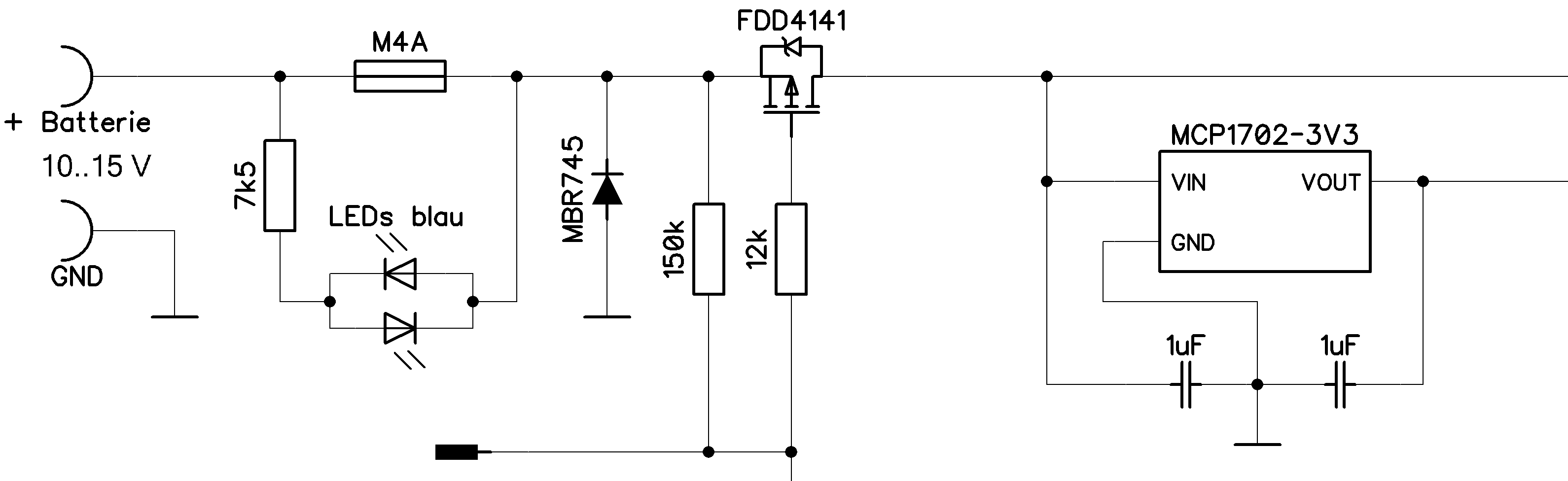
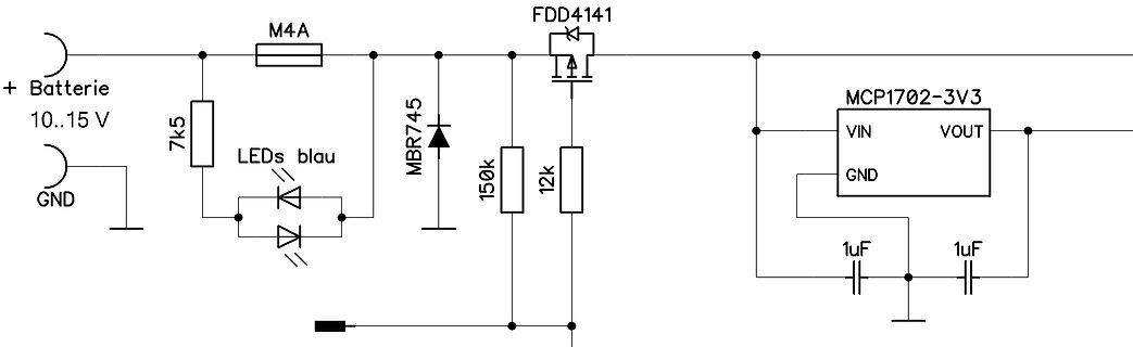
Schaltplan einer Spannungsregelung mit LED-Anzeige
+ Batterie 10..15 V M4A 7k5 LEDs blau MBR745 150k 12k FDD4141 MCP1702-3V3 VIN VOUT GND 1uF 1uF
in „Verpolungschutz für MCU und PHY“ · Mikrocontroller und Digitale Elektronik · · Schaltpläne
-
 Bild
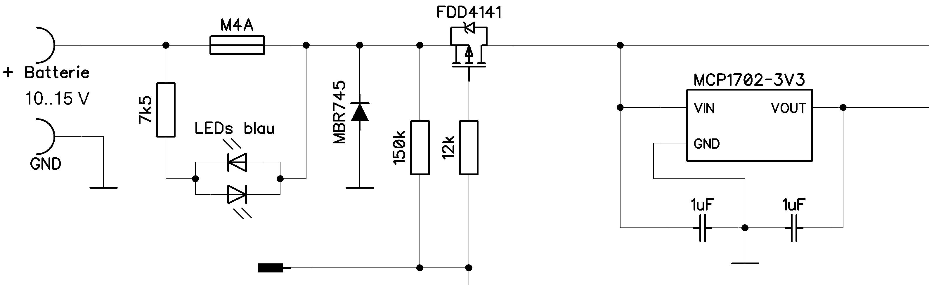
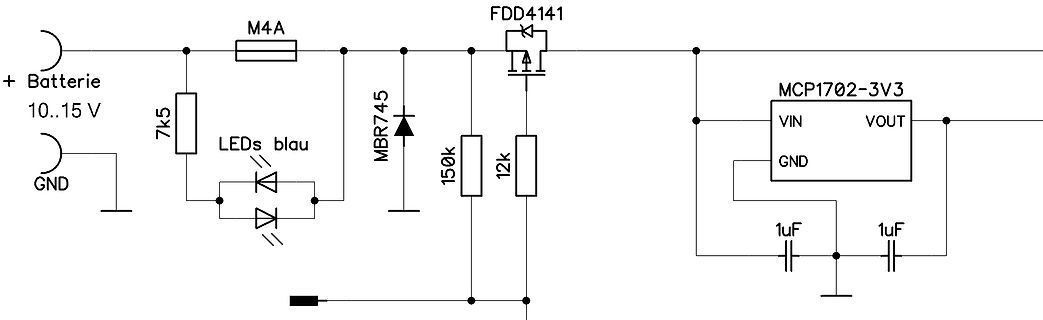
Schaltplan einer Spannungsregelung mit LED-Anzeige
+ Batterie 10..15 V M4A 7k5 LEDs blau MBR745 150k 12k FDD4141 MCP1702-3V3 VIN VOUT 1uF 1uF GND
in „Verpolungschutz für MCU und PHY“ · Mikrocontroller und Digitale Elektronik · · Schaltpläne
-
PDF
lm2574.pdf
selection guide. Table 1. Diode Selection Guide 1-A DIODES V R SCHOTTKY FAST RECOVERY 1N5817 20 V SR102 MBR120P 1N5818 SR103 The following diodes are all rated to 100 V 30 V 11DQ03 MBR130P 10JQ030 1N5819 SR104 40 V 11DQ04 11DF1 11JQ04 10JF1 MBR140P MUR110 HER102 MBR150 50 V SR105 11DQ05 11JQ05 MBR160 SR106
in „[V] kleines Konvolut ältere DIL / DIP ICs (8€)“ · Markt ·
-
PDF
Short-Circuit_Protection_for_Boost_Regulators.pdf
cell to 5V ® The LTC 1477 protected high side switch contains boostconverterwithoutputcurrentlimitedto150mA. an internal, low loss NMOS power switch. It provides The LT1304 generates 5V at the source of Q1, which, protection to external circuits in two ways: switch with its gate grounded through R1 and
in „Laden größerer Kapazitäten“ · Analoge Elektronik und Schaltungstechnik ·
-
PDF
Short-Circuit_Protection_for_Boost_Regulators.pdf
cell to 5V ® The LTC 1477 protected high side switch contains boostconverterwithoutputcurrentlimitedto150mA. an internal, low loss NMOS power switch. It provides The LT1304 generates 5V at the source of Q1, which, protection to external circuits in two ways: switch with its gate grounded through R1 and
in „Autobatterie mit zweiter Batterie laden“ · Analoge Elektronik und Schaltungstechnik ·
-
PDF
dn154f.pdf
cell to 5V ® The LTC 1477 protected high side switch contains boostconverterwithoutputcurrentlimitedto150mA. an internal, low loss NMOS power switch. It provides The LT1304 generates 5V at the source of Q1, which, protection to external circuits in two ways: switch with its gate grounded through R1 and
in „TPS61175 Overccurent Protection Mode“ · Analoge Elektronik und Schaltungstechnik ·
-
 Bild
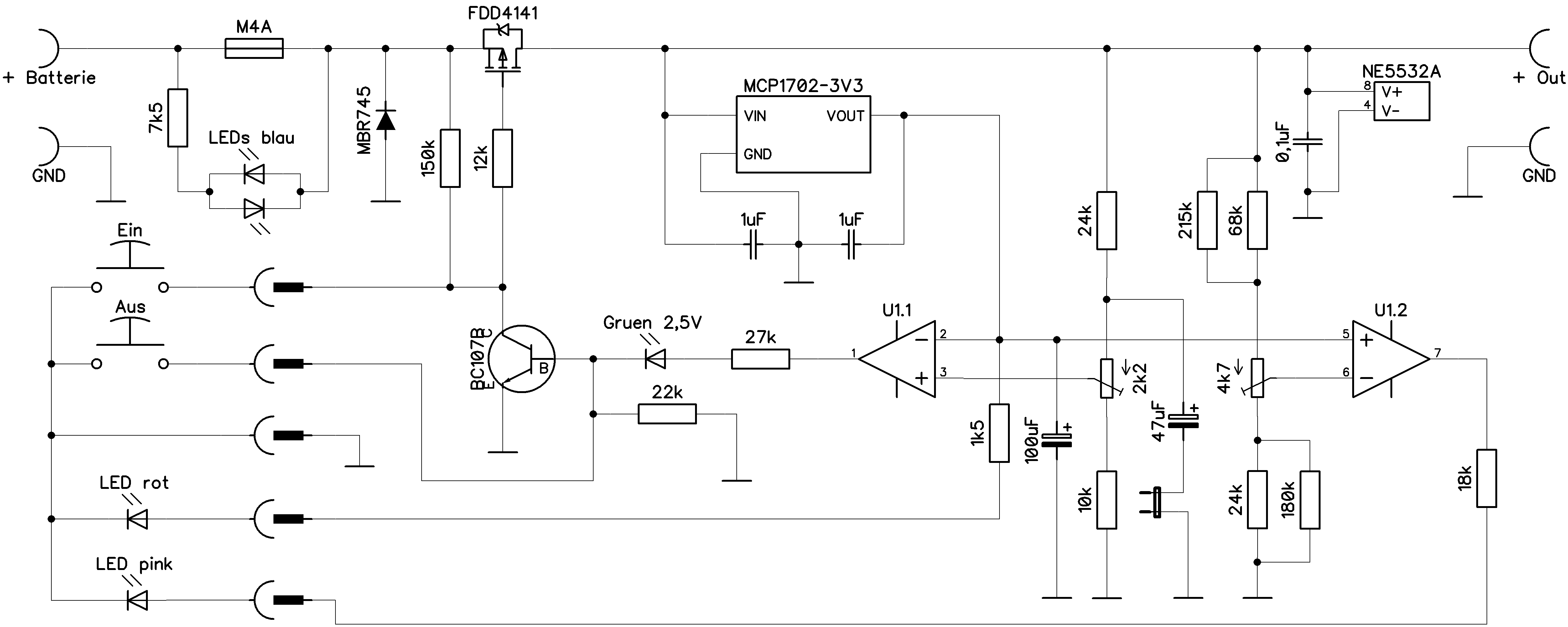
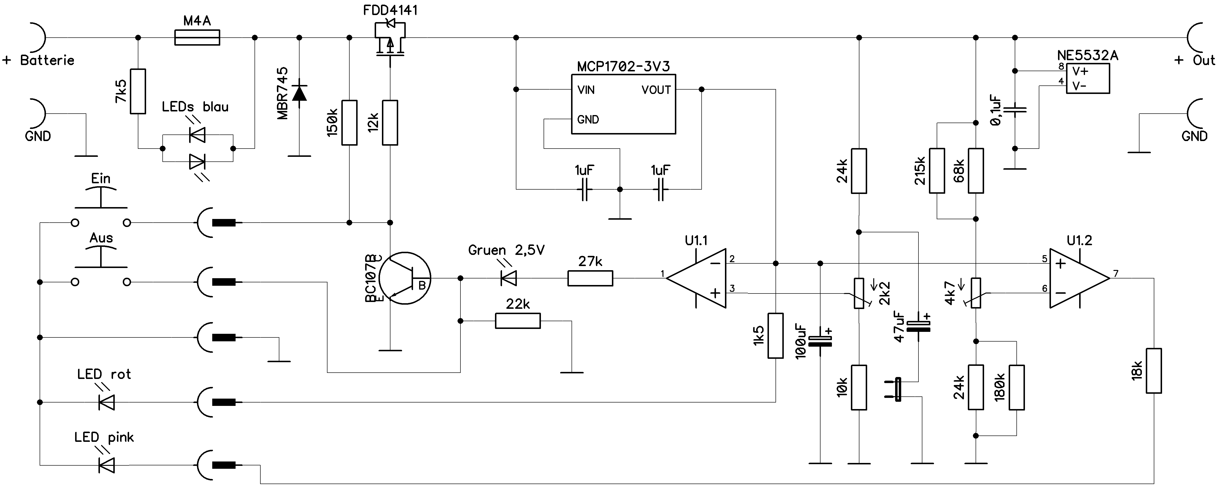
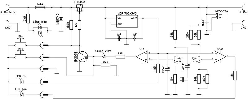
Elektronischer Schaltplan mit Operationsverstärkern und LEDs
+ Batterie, M4A, FDD4141, 7k5, LEDs blau, MBR745, 150k, 12k, MCP1702-3V3, VIN, VOUT, 1uF, 1uF, 24k, 215k, 68k, NE5532A, V+, V-, GND, Aus, Ein, BC107B, Gruen 2,5V, 27k, U1.1, 22k, 1k5, 100uF, 2k2, 4k7, 18k, 24k, 180k, U1.2, LED rot, LED pink, +
in „LM393 Schwingneigung - Designtipps?“ · Analoge Elektronik und Schaltungstechnik · · Schaltpläne
-
 Bild
Schaltplan mit Spannungsregler und Operationsverstärkern
+ Batterie, 7k5, LEDs blau, M4A, FDD4141, MBR745, 150k, 12k, MCP1702-3V3, VIN, VOUT, 1uF, 1uF, 24k, 215k, 68k, NE5532A, V+, V-, + Out, GND, Aus, Ein, BC107B, Gruen 2,5V, 27k, 22k, U1.1, 1k5, 100uF, 2k2, 4k7, 24k, 180k, U1.2, LED rot, LED pink
in „Tiefenentladungsschutzschaltung für LiPo“ · Analoge Elektronik und Schaltungstechnik · · Schaltpläne
-
 Bild
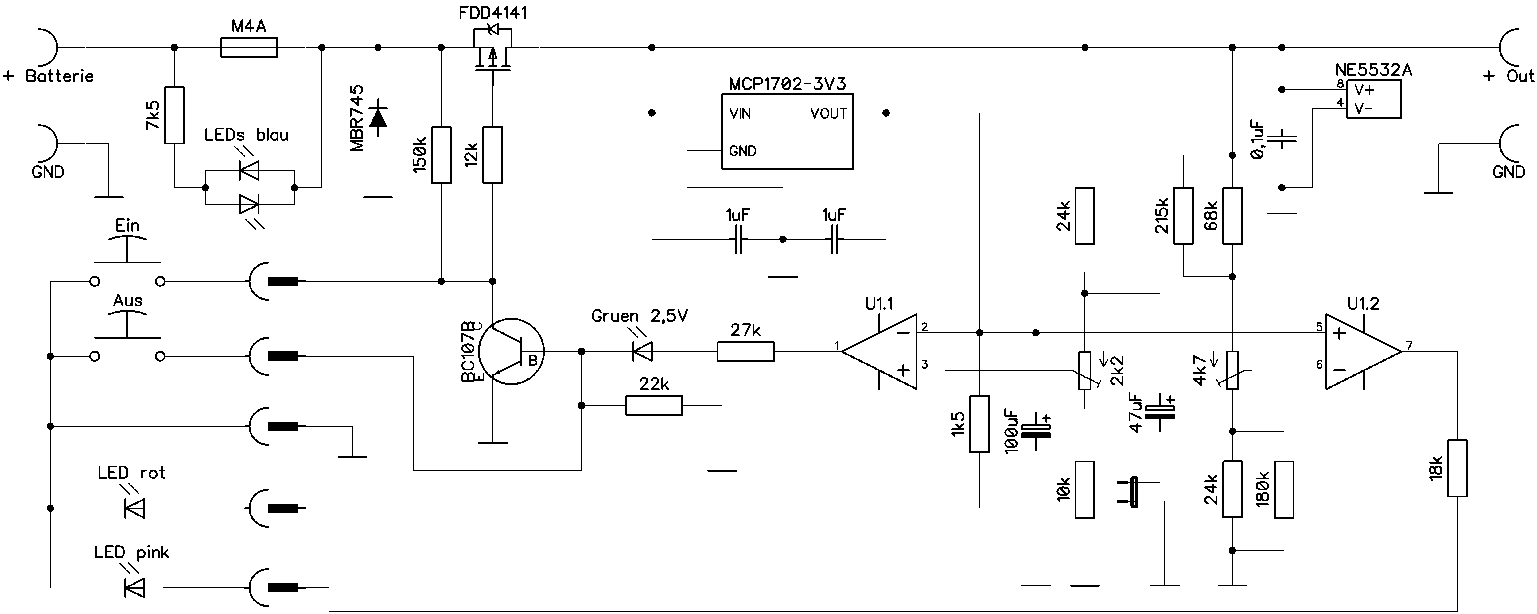
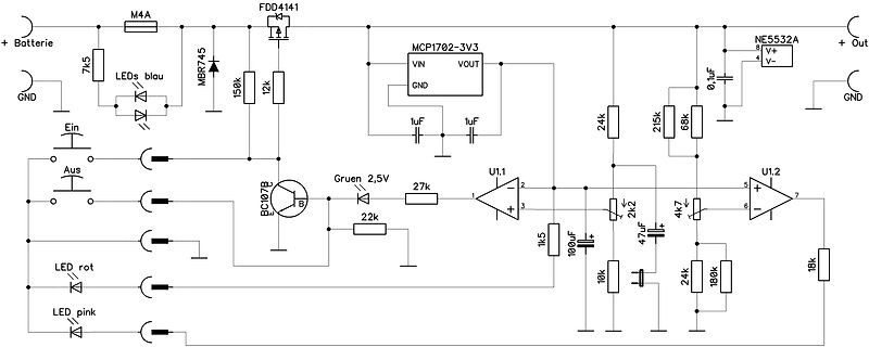
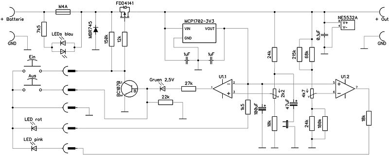
Schaltplan mit Operationsverstärkern und Spannungsregler
+ Batterie, M4A, FDD4141, 7k5, LEDs blau, MBR745, 150k, 12k, MCP1702-3V3, VIN, VOUT, 1uF, 1uF, 24k, 215k, 68k, NE5532A, V+, V-, + Out, GND, Aus, Ein, BC107B, Gruen 2,5V, 27k, 22k, U1.1, 1k5, 100uF, 2k2, 4k7, 24k, 180k, U1.2, LED rot, LED pink
in „Entladekreis für 6S Lipos, geht das so?“ · Analoge Elektronik und Schaltungstechnik · · Schaltpläne
-
PDF
lm2679-adj.pdf
C6 33 16 0.96 1000 16 1.3 3300 10 2.18 820 35 1.62 C7 100 16 1.92 150 35 0.65 3900 10 2.36 1000 35 1.73 C8 150 16 2.28 470 35 1.3 6800 10 2.68 2200 35 2.8 C9 100 20 2.25 680 35 1.4 180 16 0.41 56 50 0.36 C10 47 25 2.09 1000 35 1.7 270 16 0.55 100 50 0.5 C11 220 63 0.76
in „Schaltregler Schaltplan und Layout Kontrolle“ · Analoge Elektronik und Schaltungstechnik ·
-
PDF
1932f.pdf
LEAD PLASTIC SOT-23 TJMAX 125°C,JA 250°C/W LTST Storage Temperature Range................. –65°C to 150°C Lead Temperature (Soldering, 10 sec)..................300°C ConsultLTCMarketingforpartsspecifiedwithwideroperatingtemperatureranges. ELECTRICAL CHARACTERISTICS The denotes specifications that apply
in „step up converter 3,6V -> 8 LED's“ · Mikrocontroller und Digitale Elektronik ·
-
PDF
LT1932.pdf
LEAD PLASTIC SOT-23 TJMAX 125°C,JA 250°C/W LTST Storage Temperature Range................. –65°C to 150°C Lead Temperature (Soldering, 10 sec)..................300°C ConsultLTCMarketingforpartsspecifiedwithwideroperatingtemperatureranges. ELECTRICAL CHARACTERISTICS The denotes specifications that apply
in „IC LED Ansteuerung LTST“ · Analoge Elektronik und Schaltungstechnik ·
-
PDF
1933fe.pdf
2mm× 3mm) Plastic DFN –40°C to 150°C LT1933ES6 LT1933ES6#TR LTAGN 6-Lead Plastic TSOT-23 –40°C to 85°C LT1933IS6 LT1933IS6#TR LTAGP 6-Lead Plastic TSOT-23 –40°C to 125°C LT1933HS6 LT1933HS6#TR LTDDQ 6-Lead Plastic TSOT-23 –40°C to 150
in „Kann ich eine BAS85 problemslos an Stelle einer 1N4148 verwenden?“ · Mikrocontroller und Digitale Elektronik ·
-
PDF
1933fe.pdf
2mm× 3mm) Plastic DFN –40°C to 150°C LT1933ES6 LT1933ES6#TR LTAGN 6-Lead Plastic TSOT-23 –40°C to 85°C LT1933IS6 LT1933IS6#TR LTAGP 6-Lead Plastic TSOT-23 –40°C to 125°C LT1933HS6 LT1933HS6#TR LTDDQ 6-Lead Plastic TSOT-23 –40°C to 150
in „LT Spice ein IC von Texas Insturments einbinden“ · Analoge Elektronik und Schaltungstechnik ·
-
 Bild
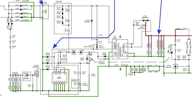
Elektronischer Schaltplan eines Netzteils
D4144 1N4007S D4145 1N4007S C4149 0.010UF/250V OPTION ZD4148 ZJ398 ZD4149 ZJ398 R4148 R4150 ZD4151 P6KE150A C4153 10000PF/630V T4140 EE30 R4154 10 ZD4147 47PF/1KV D4146 1N4007S D4168 UF400 C4155 1050/N(XA) C4156 2200PF/400V C4160 100N R4167 10U-K U4143 KIA2431AP R4158 3K3 R4157 9R R4163 47F D4149 MBR2060PT
in „AV-Receiver Schaltnetzteil Reparatur“ · Analoge Elektronik und Schaltungstechnik · · Schaltpläne
-
PDF
Vishay_Diode_Marking.pdf
120A 120C SMA5J8.0A 5AR 5AR BYG20G BYG20G P4SMA130A 130A 130C SMA5J8.5 5AS 5AS BYG20J BYG20J P4SMA150A 150A 150C SMA5J8.5A 5AT 5AT BYG21K BYG21K P4SMA160A 160A 160C SMA5J9.0 5AU 5AU BYG21M BYG21M P4SMA170A 170A 170C SMA5J9.0A 5AV 5AV BYG22A BYG22A P4SMA180A 180A 180C SMA5J10 5AW 5AW BYG22B BYG22B P4SMA200A
in „Unbekanntes Bauteil“ · Mikrocontroller und Digitale Elektronik ·
-
PDF
marking.pdf
120A 120C SMA5J8.0A 5AR 5AR BYG20G BYG20G P4SMA130A 130A 130C SMA5J8.5 5AS 5AS BYG20J BYG20J P4SMA150A 150A 150C SMA5J8.5A 5AT 5AT BYG21K BYG21K P4SMA160A 160A 160C SMA5J9.0 5AU 5AU BYG21M BYG21M P4SMA170A 170A 170C SMA5J9.0A 5AV 5AV BYG22A BYG22A P4SMA180A 180A 180C SMA5J10 5AW 5AW BYG22B BYG22B P4SMA200A
in „Suche Datenblatt zu S422“ · Mikrocontroller und Digitale Elektronik ·
-
PDF
marking.pdf
120A 120C SMA5J8.0A 5AR 5AR BYG20G BYG20G P4SMA130A 130A 130C SMA5J8.5 5AS 5AS BYG20J BYG20J P4SMA150A 150A 150C SMA5J8.5A 5AT 5AT BYG21K BYG21K P4SMA160A 160A 160C SMA5J9.0 5AU 5AU BYG21M BYG21M P4SMA170A 170A 170C SMA5J9.0A 5AV 5AV BYG22A BYG22A P4SMA180A 180A 180C SMA5J10 5AW 5AW BYG22B BYG22B P4SMA200A
in „Suche die Bezeichnung eines Bauteils“ · Analoge Elektronik und Schaltungstechnik ·
-
PDF
88912_Marking_Diodes_Vishay-061201.pdf
120A 120C SMA5J8.0A 5AR 5AR BYG20G BYG20G P4SMA130A 130A 130C SMA5J8.5 5AS 5AS BYG20J BYG20J P4SMA150A 150A 150C SMA5J8.5A 5AT 5AT BYG21K BYG21K P4SMA160A 160A 160C SMA5J9.0 5AU 5AU BYG21M BYG21M P4SMA170A 170A 170C SMA5J9.0A 5AV 5AV BYG22A BYG22A P4SMA180A 180A 180C SMA5J10 5AW 5AW BYG22B BYG22B P4SMA200A
in „Bauteil identifizieren diode, SMC, "G DE 47"“ · Mikrocontroller und Digitale Elektronik ·
-
PDF
LM2677_2000.pdf
C6 33 16 0.96 1000 16 1.3 3300 10 2.18 820 35 1.62 C7 100 16 1.92 150 35 0.65 3900 10 2.36 1000 35 1.73 C8 150 16 2.28 470 35 1.3 6800 10 2.68 2200 35 2.8 C9 100 20 2.25 680 35 1.4 180 16 0.41 56 50 0.36 C10 47 25 2.09 1000 35 1.7 270 16 0.55 100 50 0.5 C11 220 63 0.76
in „On-Chip Induktivität“ · Analoge Elektronik und Schaltungstechnik ·
-
PDF
an44fa.pdf
OPEN H ( ( 120 I 6 C I E 100 T 5 R = 10k Q E LIM R 80 R 4 F 150°C U N 60 T 3 H –55°C P I T 2 R LIM= 5k W 40 25°C O S 1 20 *MULTIPLY CURRENTS BY 0.4 FOR LT1076 0 0 0 0.5 1.0 1.5 2.0 2.5 3.0 –50 –25 0 25 50 75 100 125 150 ° FEEDBACK PIN VOLTAGE (V) JUNCTION TEMPERATURE
in „Festspannungsregler, Alternativen ?“ · Analoge Elektronik und Schaltungstechnik ·
-
PDF
Schematic_Netzteil-TL071-v.2_2026-10-22.pdf
4.7k R8 1.5k C22 BZX55C3V3 R9 C3 B 2 2.2k 220p B Set C4 f SW1 e 3 R11 47p R r R10 Umax V o 10k 2 R12 150k 4.7n + U2 D4 1 3 S 3 1k TL071CP C5 1 U1 1 U3 1 D6 C6 2 TL431 1 +12V 5 +12V 100n 5 7 7 47u MBR10100F R27 R13 R14 2 4.7k 10k 8.2k 2 R15 6 R16 D7 D8 6 6.6k 3 4.7k 3 Q6 8 4 GND 8 4 4 C21 R26 D11 2 -12V
in „Nebenprojekt: Analoges Labornetzteil inkl. Schaltplan und Messungen“ · Projekte & Code ·
-
PDF
top247.pdf
Output Power: 30 W Regulation: ± 4% CY1 Efficiency: ≥ 79% 2.2 nF Ripple: ≤ 50 mV pk-pk C14 R15 1 nF 150 Ω L3 12 V 3.3 µH @ 2.5 A C3 R3 4.7 nF 68 kΩ D8 C10 C11 C12 1 kV 2 W MBR1060 560 µF 560 µF 220 µF 35 V 35 V 35 V BR1 D1 600 V UF4005 RTN 2A R4 D2 L1 2 MΩ 1N4148 R6 20 mH 1/2 W 150 Ω R8 R1 T1 C6 150 Ω
in „Hilfe bei Reparatur SNT Laderegler“ · Analoge Elektronik und Schaltungstechnik ·
-
PDF
Voltageinverter.pdf
300 μA and oper-table oscillator d ating efficiency greater than 90% at most loads, the LM2662/Hz/150 kHz LM2663 provides ideal performance for batte■y(LM2663) low current shutdown mode a tems. The LM2662/LM2663 may also be used as a positive p voltage doubler. Applications a capacitor to the OSC pin
in „Das große ADC Quiz“ · Mikrocontroller und Digitale Elektronik ·
-
PDF
LTC1174.pdf
............................................ 1A Storage Temperature Range................ –65°C to 150°C Switch Voltage (Pin 5) Lead Temperature (Soldering, 10 sec)................. 300°C LTC1174................................................. V – 13.5V IN LTC1174HV..................................
in „DC/DC Wandler LTC1174 Verhalten bei Shutdown?“ · Mikrocontroller und Digitale Elektronik ·
-
PDF
3703fc.pdf
C I C 45 E 0.800 A0.95 V E M E O0.90 40 R N 0.799 35 0.85 30 0.798 0.80 –50 –25 0 25 50 75 100 125 150 –50 –25 0 25 50 75 100 125 150 –50 –25 0 25 50 75 100 125 150 TEMPERATURE (°C) TEMPERATURE (°C) TEMPERATURE (°C) 3703 G07 3703 G08 3703 G09 Driver Peak Source Current vs Driver Pull-Down R vs Driver
in „Längs- oder Querregler 40V 250W als Überspannungsschutz für Tiefstellsetzer“ · Analoge Elektronik und Schaltungstechnik ·
-
PDF
MAX1700-MAX1701.pdf
.........POUT...............-0.3V,Vmperature......................................................+150°C 1 CLK/SEL, AIN, REF, FB, LBP, LBN, POUT to GND............-0.3V,rage Temperature Range.............................-65°C to +160°C V OUT+0.3V ......................................................
in „5V Spannung aus Lipo?“ · Mikrocontroller und Digitale Elektronik ·
-
PDF
TimerPumpe_S01_CMOS4060.pdf
86g TL494AW SO16 10mA 150kHz (UC3524) Fuse 15A 4x 220uF 63V LowESR 2,95€ 30pcs SV3.5-4 2,5-4mm2 37A iDia4,3mm 24,8x8mm 1,26 Euro Step-Up Boost 10-32Vin max.10Ain 12-35Vo 6Aout 100W max.150W+Fan 65x56,5x23mm, UC3843A SO8, 78L09
in „Laufzeitbegrenzung für 12V Pumpe mit Akku, Solarmodul, Step-Up, Zeitschaltuhrbetrieb LED-Anzeige MPP“ · Projekte & Code ·
-
PDF
an90f.pdf
LT1004 2.5V CCLAMPT A3 + R LT1789 1Ω G 1% RG – LT1431 2.5V 22.2k* 1M 1N4001 A = 10 GND SELF-ENABLE MBR0520 470Ω 1000pF 5V 5V 2N5060 * = 1% METAL FILM RESISTOR 0.1µF 187k* +V R = 1N4148 FB1 LTC1696 = 1N5712 100k* GND OUT 560Ω = LASER OPEN LASER PROTECTION AN90 F06 Figure 6. Figure 5’s Circuit, Augmented
in „Mosfet Laser Treiber“ · Mikrocontroller und Digitale Elektronik ·
-
PDF
lm2596.pdf
temperature Infrared (10 s) 245 °C NDZ package, soldering (10 s) 260 Maximum junction temperature 150 °C Storage temperature, Tstg –65 150 °C (1) Stresses beyond those listed under Absolute Maximum Ratings may cause permanent damage to the device. These are stress ratings only, which do not imply functional
in „[V] 15 ST. Stepdown SIMPLE SWITCHER LM2596S-12V , 3A, 400kHz, TO263 (alle 12€)“ · Markt ·
-
PDF
lm2596.pdf
temperature Infrared (10 s) 245 °C NDZ package, soldering (10 s) 260 Maximum junction temperature 150 °C Storage temperature, Tstg –65 150 °C (1) Stresses beyond those listed under Absolute Maximum Ratings may cause permanent damage to the device. These are stress ratings only, which do not imply functional
in „[V] 15 ST. Stepdown SIMPLE SWITCHER LM2596S-12V , 3A, 400kHz, TO263 (alle 18€)“ · Markt ·
-
Datei
u-boot-output.txt
0x0000000000000000-0x000000000003FFFF] "PRELOADER" (512 blocks) [PART] [0x0000000000000000-0x000000000003FFFF] "MBR" (512 blocks) [PART] [0x0000000000040000-0x00000000000BFFFF] "UBOOT" (1024 blocks) [PART] [0x00000000000C0000-0x00000000000FFFFF] "CONFIG" (512 blocks) [PART] [0x0000000000100000-0x000000000013FFFF]
in „Linux Kernel 5.1.1. auf dem BPi-R2“ · PC Hard- und Software ·
-
PDF
3971fd.pdf
with a smaller reverse bias On Semiconductor rating. Therefore, superior leakage performance can be MBR0520L 20 0.5 30 achievedattheexpenseofdiodesize.Table4listsseveral MBR0540 40 0.5 620 0.4 Schottky diodes and their manufacturers. MBRM120E 20 1 530 595 0.5 MBRM140 40 1 550 20 Ceramic Capacitors Diodes
in „[V] LT3971IDD-5PBF-ND“ · Markt ·
-
PDF
LM2594HVM-5.0_Datenblatt.pdf
120/25 120/25 100/16 33/25 9 150 L10 82/16 82/16 100/16 33/25 0.2 20 220 L9 120/16 120/16 100/16 33/25 40 330 L8 120/16 120/16 100/16 33/25 12 0.5 15 68 L21 82/25 82/25 100/16 15/25 18 150 L19 82/25 82/25 100/16 15/25 30 220 L27 82
in „Idee für ein ||transportables|| Handyladegerät“ · Analoge Elektronik und Schaltungstechnik ·
-
PDF
Grundig-DVDP-7000-Service-Manual.pdf
100n 15 7 FB D2-1 S2 J605 100n 100n 14 EN D M 5 4 D613 -12VA 1 AOL- 13 N O D2-2 G2 2 AOL+_P 12 G C R150 NC/1.1K 11 NC/MPS1410ES 1% TPC8305 10 4 6 D607 MBR0530 CON2 9 R148 NC/10K EC623 to Speaker 8 MBR0530 7 C615 10u/16V 6 EC622 C144 NC/10n 1uf 5 3 TFT_Power_C 4 10u/16V +5V +12VA AOL- 3 +5V L603 C618 D608 MBR0530 2 to P. 2-14 R621 2 1 20 AOL+_P 1 +3.3V J607 10uH(0805) 1uf C619 L606FB600 10K TV_ENABLE C626 D609 R612 EC624 CON15 1 2 EC618 MBR0530 1.8M 5P to P. 2-8 3 4 100n 4.7u/16V 5 1 10u/16V C6 C5 J606 5
in „800x480-Farbdisplay mit uC verwenden“ · Mikrocontroller und Digitale Elektronik ·
-
PDF
LM2660_DC_Inverter.pdf
(TA = 25˚C) (Note 3) 735 mW 500 mW M Supply Voltage (V+ to GND, or GND to OUT) 6V TJ Max (Note 3) 150˚C 150˚C L LV (OUT − 0.3V) to (GND + 3V) θJA (Note 3) 170˚C/W 250˚C/W FC, OSC The least negative of (OUT − 0.3V) Operating Junction or (V+ − 6V) to (V+ + 0.3V) Temperature V+ and OUT Continuous Output Current 120 mA Range −40˚C to +85˚C Storage Temperature Range −65˚C to +150˚C Output Short-Circuit Duration to GND (Note 2) 1 sec. Lead Temperature 300˚C (Soldering, 10 seconds) ESD Rating 2 kV Electrical Characteristics Limits in standard typeface are foJ T = 25˚C, and limits
in „Negative Betriebsspannung erzeugen“ · Analoge Elektronik und Schaltungstechnik ·
-
PDF
LM2661.pdf
(TA = 25˚C) (Note 3) 735 mW 500 mW M Supply Voltage (V+ to GND, or GND to OUT) 6V TJ Max (Note 3) 150˚C 150˚C L LV (OUT − 0.3V) to (GND + 3V) θJA (Note 3) 170˚C/W 250˚C/W FC, OSC The least negative of (OUT − 0.3V) Operating Junction or (V+ − 6V) to (V+ + 0.3V) Temperature V+ and OUT Continuous Output Current 120 mA Range −40˚C to +85˚C Storage Temperature Range −65˚C to +150˚C Output Short-Circuit Duration to GND (Note 2) 1 sec. Lead Temperature 300˚C (Soldering, 10 seconds) ESD Rating 2 kV Electrical Characteristics Limits in standard typeface are foJ T = 25˚C, and limits
in „pegelanpassung analog“ · Analoge Elektronik und Schaltungstechnik ·
-
PDF
RPI-PICO-R3-PUBLIC-SCHEMATIC.pdf
VIN L LVOUT GPIO3 5 36 3 USB_DP TP2 R10 C1 8 10 C2 GPIO4 6 35 ADC_VREF D 690-005-298-486 4 TP3 5K6 MBR120VLSFT1G R2 47u VINA FB 47u GPIO5 GPIO28_ADC2 D 5 7 34 63mW 100K M2012 M2012 8 33 AGND 1% 63mW 6.3V 6.3V GPIO6 9 32 GPIO27_ADC1 M1005 1% X5R X5R GPIO7 10 31 GPIO26_ADC0 8 9 M1005 20% 20% GPIO8 11 30
in „PiPico externe Spannungsversorgung“ · Mikrocontroller und Digitale Elektronik ·
-
PDF
LT3474.pdf
, the inductor value, and the input and output volt- CDRH5D28-100 10 1.30 0.048 3.0 ages. CDRH5D28-150 15 1.10 0.076 3.0 CDRH73-100 10 1.68 0.072 3.4 Whentheswitchisoff,thepotentialacrosstheinductoris theoutputvoltageplusthecatchdiodedrop.Thisgivesthe CDRH73-150 15 1.33 0.130 3.4 peak-to-peak ripple
in „3W Luxeon Led energiesparend dimmen“ · Mikrocontroller und Digitale Elektronik ·
-
PDF
MAX856-Stepup.pdf
+85°C. U U CAPS ARE SPRAGUE 595 D U CAPS ARE SPRAGUE 595D 5 E 5 C200 C 0.8 R N TA= +25°C N 8 A 4 C150 C 0.6 O E E X F 3 U100 U 0.4 TA = +25°C R 2 Q Q A V TA= -40°C 1 50 0.2 TA= -40°C M 0 0 0 0 50 100 150 200 250 1.5 2.0 2.5 3.0 3.5 4.0 1.5 2.0 2.5 3.0 3.5 4.0 REFERENCE LOAD CURRENT ( A) INPUT VOLTAGE
in „Bitte mal kurz über Schaltplan drüberschauen“ · Mikrocontroller und Digitale Elektronik ·
-
PDF
MAX856-Stepup.pdf
+85°C. U U CAPS ARE SPRAGUE 595 D U CAPS ARE SPRAGUE 595D 5 E 5 C200 C 0.8 R N TA= +25°C N 8 A 4 C150 C 0.6 O E E X F 3 U100 U 0.4 TA = +25°C R 2 Q Q A V TA= -40°C 1 50 0.2 TA= -40°C M 0 0 0 0 50 100 150 200 250 1.5 2.0 2.5 3.0 3.5 4.0 1.5 2.0 2.5 3.0 3.5 4.0 REFERENCE LOAD CURRENT ( A) INPUT VOLTAGE
in „Verständnisfrage zu Shutdown Feature von Schaltregler MAX856“ · Mikrocontroller und Digitale Elektronik ·
-
PDF
Bestandsliste_mit_Preisen1.pdf
A 200V TO220 15 Stk 0,31 € 4,69 € MBR4045PT Diode Shottky 40 A 45V TO247 16 Stk 0,70 € 11,20 € MBR4060PT Diode Shottky 40 A 60V TO247 3 Stk 0,70 € 2,10 € MBR5200 Diode Shottky 5 A 200V 7 Stk 0,74 € 5,15 € 1N5817 Diode Shottky 20V 1 A SOD
in „Auflösung Elektronik Shop“ · Markt ·
-
PDF
Funktionsbeschreibung.pdf
1 27C512 IC12 1 27C256 2 BAT41 D3, D4 1 D-Sub9M 90° X1 1 GAL16V8 IC6 1 L4973_SMD U3 1 MAX232 IC5 1 MBR760 D1 1 SAB80C535 IC1 1 TL7705 IC13 2 UA9637ACP U4, U5 1 VG64P J1 1 WE-PD4 150µH L1 Jumper – Einstellungen Unabhängig von der aktuellen Betriebsart können beide Vorschübe unabhängig voneinander durch
in „[V] 2-fach ISEL Lineareinheit 300cm mit Zahnriemenantrieb Schrittmotor und Steuerung“ · Markt ·