-
Datei
WS2812.h
/* * Single WS2812 - 16M Arduino support * License: GNU GPL v2 (see License.txt) */ #ifndef WS2812_H_ #define WS2812_H_ #ifndef F_CPU #define F_CPU 16000000UL #endif #include <Arduino.h> // PD4 #define mask 0b00001000 #define ws2812_PORTREG PORTD #define ws2812_DDREG DDRD void ws2812_init(); void ws2812_sendarray(uint8_t *data, uint16_t datlen); #endif /* WS2812_H_ */
in „Ein "non bloated" arduino 328p WS2812 treiber“ · Projekte & Code ·
-
Datei
README.txt
some LEDs as strip ws2812_tinymega.s Implementation for ATtiny and ATmega ws2812_xmega.s Implementation for ATxmega asmdefs.h Used in the ASM source, implements some handy macros gammacorrection.h Some definitions for gamma
in „AVR ASM ws2811 / ws2812 Ansteuerung mit FastPWM“ · Projekte & Code ·
-
PDF
WS2812B-V5.pdf
WS2812B Ver. No.: V5 Intelligent control LED integrated light source Features and Benefits The control circuit and the LED share the only power source. Control circuit and RGB chip are integrated in
in „PWM-Signal verstärken“ · Mikrocontroller und Digitale Elektronik ·
-
PDF
WS2812B-V5.pdf
WS2812B Ver. No.: V5 Intelligent control LED integrated light source Features and Benefits The control circuit and the LED share the only power source. Control circuit and RGB chip are integrated in
in „WS2812B mit 3.3V ansteuern“ · Mikrocontroller und Digitale Elektronik ·
-
PDF
WS2812B__Ver._No._V5__EN_19112715001349.pdf
WS2812B Ver. No.: V5 Intelligent control LED integrated light source Features and Benefits The control circuit and the LED share the only power source. Control circuit and RGB chip are integrated in
in „Adressierbare RGB LEDs 3.3V gesucht“ · Mikrocontroller und Digitale Elektronik ·
-
PDF
WS2812B_Datasheet_2017.pdf
WS2812B Intelligent control LED integrated light source Features and Benefits The control circuit and the LED share the only power source. Control circuit and RGB chip are integrated in a package of
in „WS2812 Ansteuerung“ · Mikrocontroller und Digitale Elektronik ·
-
PDF
WS2812B-MINI.pdf
WS2812B-Mini Intelligent external control LED Integrated light source Features and Benefits The IC’s control circuit and the LED share the same power supply. Control circuit and RGB chip are integrated
in „Indirekte Beleuchtung mit ca. 30m LED Streifen“ · Analoge Elektronik und Schaltungstechnik ·
-
Datei
WS2812.h
#define WS2812_LAT LATAbits.LATA0 #define WS2812_TRIS TRISAbits.TRISA0 void WS2812_Init(void); void WS2812_Write(unsigned char *data, int number_leds); void WS2812_WriteSame(unsigned char R, unsigned char G, unsigned char B, int number_leds); inline void WS2812_WriteBit(unsigned char DataBit); void WS2812_WriteByte(unsigned char DataByte);
in „Einfacher Webserver mit PIC24 + ESP8266“ · Projekte & Code ·
-
Datei
ws2812_config.h
/* * light_ws2812_config.h * * Created: 18.01.2014 09:58:15 * * User Configuration file for the light_ws2812_lib * */ #ifndef WS2812_CONFIG_H_ #define WS2812_CONFIG_H_ /////////////////////////////////////////////
in „ws2812 mit atmega32“ · Mikrocontroller und Digitale Elektronik ·
-
Datei
lightws_config.h
/* * light_ws2812_config.h * * Created: 18.01.2014 09:58:15 * * User Configuration file for the light_ws2812_lib * */ #ifndef WS2812_CONFIG_H_ #define WS2812_CONFIG_H_ /////////////////////////////////////////////
in „arrays und struct in funktionen“ · Mikrocontroller und Digitale Elektronik ·
-
PDF
WS2812B-V4.pdf
WS2812B-V4 Intelligent control LED integrated light source Features and Benefits The control circuit and the LED share the only power source. Control circuit and RGB chip are integrated in a package
in „PWM-Signal verstärken“ · Mikrocontroller und Digitale Elektronik ·
-
Datei
main.c
44/84/13/13A) mask=_BV(PB0); #endif DDRB|=mask; while(1) { unsigned int winkel; unsigned char r, g, b; for (winkel=0; winkel < 256; winkel++) { hsv_to_rgb(winkel, 100, 100, &r, &g, &b); led[0].r=r; led[0].g=g; led[0].b=b; ws2812_sendarray((uint8_t *)&led[0],3); _delay_ms(50); } // led[0].r=255;led[0].g=255;led[0].b=0; // green // ws2812_sendarray((uint8_t *)&led[0],3); // _delay_ms(500); // led[0].r=0;led[0].g=00;led[0].b=255; // blue // ws2812_sendarray((uint8_t *)&led[0],3); // _delay_ms(500); } }
in „Lightweight WS2811/WS2812 Library“ · Mikrocontroller und Digitale Elektronik ·
-
Datei
WS2812Ctrl.cpp
/*----------------------------------------------------------------------- WS2812Ctrl.c Control of LED Strip with WS2812B driver ----------------------------------------------------------------------- Last committed: $Revision: 05 $ Last changed by: $Author: Thomas.Stief@web.de
-
Datei
main24.s
w0,[w1++] mov #0xFF,w0 mov.b w0,[w1++] mov #0xFF,w0 mov.b w0,[w1++] call transmit_WS2812 bra $ ;*********************************************************************************************************** transmit_WS2812: mov #RGB_bytes,w1 mov #(number_rgb_bytes+RGB_bytes),w3 ;Last RGB_byte address ws2812loop_1: mov.b [w1++],w2 mov #4,w4 ws2812loop_2: mov #0xF0F0,w0 ;Send 2x '1' btss w2,#7 mov.b #0xC0,w0 ;Send '0' swap w0 ;Swap byte W0 btss w2,#6 mov.b #0xC0,w0 ;Send '0' rlnc w2,w2 rlnc w2,w2 btsc
in „[ASM & C] PIC12/PIC18/PIC24 WS2812 SPI Library“ · Projekte & Code ·
-
Datei
WS2812_Glediator.ino
of WS2812 pixels # // # // Adjust the correct DATA PIN and the correct NUMBER OF PIXELS you are using # // in the definitions section below before uploading this sketch to your # // Arduino device. # // #
in „Auswahl zweier Arduino Sketches“ · Mikrocontroller und Digitale Elektronik ·
-
Datei
ws2812b.h
#ifndef WS2812B #define WS2812B #ifdef STM32F10X_MD #include <stm32f10x.h> #include <irq_stm32f103.h> #endif #if defined(STM32F303xE) || defined(STM32F303xD) || defined(STM32F303xC) #include <stm32f3xx.h> #include
in „WS2812b Pixel mit STM32 und PWM/DMA ohne Hal“ · Mikrocontroller und Digitale Elektronik ·
-
Datei
led_modes.c
/* * led_modes.c * * Created: 05.05.2016 23:25:26 * Author: Hannes */ #include "includes/light_ws2812.h" #include <math.h> #include <stdlib.h> #define MAX 255 #define BASE 10 #define RESOLUTION 64 //number of steps to increment the brightness value #define NOF_COLORS 14 #define NOF_MODES (NOF_COLORS
in „Code zu groß für AtTiny45“ · Mikrocontroller und Digitale Elektronik ·
-
Datei
ws6812_test_zwo.c
ANZAHL_LEDS 525 #include <util/delay.h> #include <avr/io.h> #include <avr/interrupt.h> #include "light_ws2812.h" struct cRGBW led[ANZAHL_LEDS]; int main(void) { while(1) { for (uint16_t i = 0; i < ANZAHL_LEDS; i++) { led[i].r=128;led[i].g=00;led[i].b=0;led[i].w=0; // Write red to array } ws2812_setleds_rgbw
in „atmega328; data memory voll, wie umlagern“ · Mikrocontroller und Digitale Elektronik ·
-
PDF
WS2812.pdf
WS2812 Intelligent control LED integrated light source Features and Benefits l Control circuit and RGB chip are integrated in a package of 5050 components, form a complete control of pixel point. l Built-in
in „WS2812/2811 mit PIC asm.Verzweiflung!“ · Mikrocontroller und Digitale Elektronik ·
-
PDF
WS2812preliminary.pdf
WS2812 Intelligent control LED integrated light source Features and Benefits l Control circuit and RGB chip are integrated in a package of 5050 components, form a complete control of pixel point. l Built-in
in „[Mitbestellung] SMD5050 RGB-LED mit integriertem 8-bit PWM Controller“ · Markt ·
-
PDF
WS2812.pdf
WS2812 Intelligent control LED integrated light source Features and Benefits l Control circuit and RGB chip are integrated in a package of 5050 components, form a complete control of pixel point. l Built-in
in „Kabelquerschnitt für 5V?“ · Analoge Elektronik und Schaltungstechnik ·
-
PDF
WS2812preliminary.pdf
WS2812 Intelligent control LED integrated light source Features and Benefits l Control circuit and RGB chip are integrated in a package of 5050 components, form a complete control of pixel point. l Built-in
in „WS2812 Timing“ · Mikrocontroller und Digitale Elektronik ·
-
Datei
ws2812c.asm
;WS2812 CONTROL ;--------------------------------------------------------------------------------- ;USING ATTINY1614 @ 5V/20MHz, WS2812B LED STRIP ;FUSE: INT.RC OSC20 ;PORT-Belegung: I/O-A0: UPDI INP-B0: ; INP-A1: INP-B1: ; INP-A2: INP-B2: ; INP-A3: INP-B3: ; OUT-A4: WS2812 DATA ; INP-A5: ; INP-A6: ; INP-A7: .EQU LEDCN = 12*3 ;LED NUMBER * 3 COLOR ;--------------------------------------------------------------------
in „WS2812 control @ ATTiny1614 (Assembler)“ · Projekte & Code ·
-
PDF
4xRGB-LED-Steuern-5V_SCH.PDF
4- 2 2 2 2 + 0 3- 1 7 2 7 3 7 4 7 2 R 4 R 4 R 1 4 R 4 1+ 1 1 1 K2 RGB-LED Daten Klemme 4 3 2 1 K3 WS2812B 3 VSS Dout 2 4 Din VDD 1 D4 WS2812B VSS Dout 3 2 4 Din VDD 1 D3 WS2812B 3 VSS Dout 2 Din VDD 4 1 D2 WS2812B VSS Dout 3 2 4 Din VDD 1 D1
in „empehlung Microcontroller WS2812B Steuern“ · Mikrocontroller und Digitale Elektronik ·
-
Datei
installation_lauflicht.c
include <avr/io.h> #include <avr/interrupt.h> #include <stdio.h> #include <stdlib.h> #include "light_ws2812.h" #define WHITE_LIGHT PORTD3 //weiße LED-Kette #define STATUS_LED PORTD4 //Status/Test-Led #define RESERVE PORTD5 //frei #define WS2812_RESERVE PORTD6 //Reserve für evtl. zweite WS2812-Kette //ws2812
in „HCSR04-US-Sensoren an Atmega328P kurioser Effekt // Entstörung“ · Mikrocontroller und Digitale Elektronik ·
-
Datei
ws2812_config.h
#ifndef WS2818_CONFIG_H_ #define WS2818_CONFIG_H_ #include <avr/io.h> #include "../defines.h" // Timing in ns #define w_zeropulse 350 #define w_onepulse 900 #define w_totalperiod 1250 // Fixed cycles used by the
in „WS2812b LED-streifen aktualisiert sich erst nach zweitem aufruf“ · Mikrocontroller und Digitale Elektronik ·
-
Datei
installation_lauflicht.c
include <avr/io.h> #include <avr/interrupt.h> #include <stdio.h> #include <stdlib.h> #include "light_ws2812.h" #define WHITE_LIGHT PORTD3 //weiße LED-Kette #define STATUS_LED PORTD4 //Status/Test-Led #define RESERVE PORTD5 //frei #define WS2812_RESERVE PORTD6 //Reserve für evtl. zweite WS2812-Kette //ws2812
in „Atmega328P: PB6/PB7 als I/O nutzen“ · Mikrocontroller und Digitale Elektronik ·
-
Datei
led_modes.c
05.05.2016 23:25:26 * Author: Hannes */ #include <math.h> #include <stdlib.h> #include "includes/light_ws2812.h" #include "config.h" #include "led_modes.h" #define MAX 255 #define RESOLUTION 64 //number of steps to increment the brightness value #define NOF_COLORS 14 #define NOF_MODES (NOF_COLORS + 3) struct
in „Code zu groß für AtTiny45“ · Mikrocontroller und Digitale Elektronik ·
-
Datei
ws2812_test2.c
/* ------------------------------------------------------- ws2812_test.c Programm zum Ansprechen von WS2812 LED's MCU : STM8S103F3 Takt : interner Takt 16 MHz 28.04.2017 R. Seelig ------------------------------------------------------ */ /* ####################
in „SDCC und struct“ · Mikrocontroller und Digitale Elektronik ·
-
Datei
tetris_io.c
----------------------------------------- */ #include "Project.h" #include "tetris_io.h" #include "ws2812.h" /* stores the color (number) of every pixel */ uint8_t TRIS_pixelArrey[GRID_DX][GRID_DY]; static void TRIS_SetPixel(uint_fast8_t x, uint_fast8_t y, uint_fast8_t color) { /* check array borders
in „ein plattformunabhängiger Tetris-Clone“ · Projekte & Code ·
-
Datei
LED_WS2812B.c
############################################################################### // Steuerung von 5 WS2812B über einen beliebigen Port //################################################################################### #include <avr/io.h> #include <util/delay.h> #include <avr/interrupt.h> #include <
in „WS2812 Ansteuerung per Bitbanging für AVR und ARM von 4 Mhz-60 Mhz“ · Projekte & Code ·
-
Datei
LED_WS2812B.c
############################################################################### // Steuerung von 5 WS2812B über einen beliebigen Port //################################################################################### #include <avr/io.h> #include <util/delay.h> #include <avr/pgmspace.h> #include "light_ws2812
in „WS2812 Ansteuerung per Bitbanging für AVR und ARM von 4 Mhz-60 Mhz“ · Projekte & Code ·
-
Datei
C_Programm.c
/* * Light_WS2812 library example - RGB_blinky * * cycles one LED through red, green, blue * * This example is configured for a ATtiny85 with PLL clock fuse set and * the WS2812 string connected to PB4. */ # define
in „ws2812 mit atmega32“ · Mikrocontroller und Digitale Elektronik ·
-
Datei
main.c
FRAMESNUM 4 // Number of frames #define FRAMESON 0b0101 // Frames for black/white // Functions void SysTick_Handler(void); void put_ws2812(struct LEDRGB led_data[], int led_num, uint8_t *serial_buf); // MAIN int main(void) { /* Initialize hardware */
in „The secret of WS2812B“ · Mikrocontroller und Digitale Elektronik ·
-
Datei
ws6812_test_zwo.c
pixel[zeile_akt][i]].r = ring_red; led[pixel[zeile_akt][i]].g = ring_green; led[pixel[zeile_akt][i]].b = ring_blue; led[pixel[zeile_akt][i]].w = ring_white; } ws2812_setleds_rgbw(led,ANZAHL_LEDS); zeile_akt++; } } int main(void) { create_matrix(ANZAHL_ZEILEN, ANZAHL_SPALTEN); while(1) { fill_background(0,0,0,0); ws2812_setleds_rgbw(led,ANZAHL_LEDS); _delay_ms(500); moving_ring_zeilen(100, 10, 0, 10, 0, 100, 100, 0); _delay_ms(500); fill_background(100,100,0,0); ws2812_setleds_rgbw(led,ANZAHL_LEDS); _delay_ms(500
in „LED-Matrix mit light_ws2812-library; Ansteuerungsgeschwindigkeit“ · Mikrocontroller und Digitale Elektronik ·
-
PDF
Anleitung-Wort-Uhr.pdf
den Nachbau wird folgende Hardware/Software benötigt. • NodeMCU (getestetes Board Lolin Version3) • WS2812B oder WS2816 RGB LED Stripes • Netzteil 5V 2A • Arduino Version 1.8.8 • 470 Ohm Widerstand • Diode oder Pegelanpasser • Optional: LDR, 10 KOhm Widerstand 16/02/2019 S e i t e | 5 Quelle: https://
in „Wortuhr Dioden Multiplex entstören“ · Analoge Elektronik und Schaltungstechnik ·
-
Datei
main.c
); // Wait for PLL to lock WS2812_Init(); LED.R=0; LED.G=1; LED.B=0; WS2812_WriteSame(LED.R,LED.G,LED.B,numberLED); LCD_Init(); Open1UART(34); // 115200Bd @32MHz (Error: -0.62% 114285.7Bd) U1FIFOClr(); Puts1UART("AT+RST\r"); __delay_ms
in „Einfacher Webserver mit PIC24 + ESP8266“ · Projekte & Code ·
-
 Bild
Bild
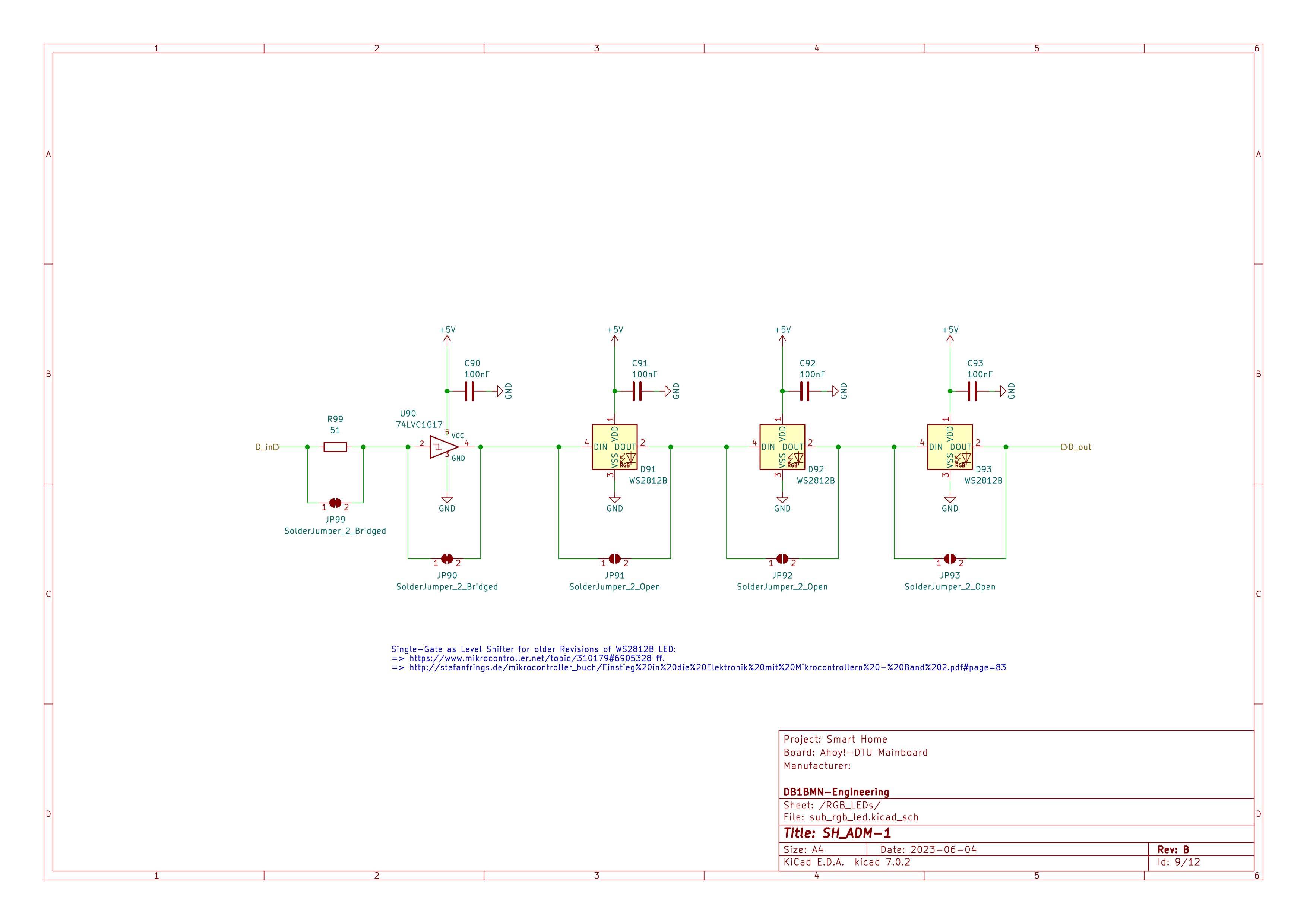
Schaltplan eines LED-Treiberschaltkreises
R99, S1, U90 74LVC1G17, D_in, GND, +5V, C90 100nF, JP99 SolderJumper_2_Bridged, JP90, C91 100nF, D91 WS2812B, DIN, DOUT, JP91 SolderJumper_2_Open, GND, C92 100nF, D92 WS2812B, DIN, DOUT, JP92 SolderJumper_2_Open, C93 100nF, D93 WS2812B, DIN, DOUT, D_out, Project: Smart Home, Board: Anydot-DTU Mainboard
in „Wortuhr Dioden Multiplex entstören“ · Analoge Elektronik und Schaltungstechnik · · Schaltpläne
-
Datei
Treppenbeleuchtung-WS2812B.ino
#include <Adafruit_NeoPixel.h> #include <Wire.h> #ifdef __AVR__ #include <avr/power.h> #endif /*******************************Variablendeklaration***********************************/ int Melder_unten = 22; // Input Bewegungsmelder unten int Melder_oben = 23; // Input Bewegungsmelder oben int Nanopixel = 6; // Output für NanoPixel LEDs int VZ = 15; // Verzögung Ansteuerung der Stufen int Dauer = 30000; // Leuchtdauer wenn alle Stufen angesteuert sind int Sperrzeit = 60000; // Sperrzeit bevor die Scheife beendet wird und die anderen Laufen kann bool BWU,BWO; float PIXEL; #define NUMPIXELS 394 // Anzahl
in „Dynamischer Variablenname in Scheife hochzählen“ · Mikrocontroller und Digitale Elektronik ·
-
Datei
main.c
at 16MHz */ #include <util/delay.h> #include <avr/io.h> #include <avr/interrupt.h> #include "light_ws2812.h" #define MAXPIX 4 #define COLORLENGTH (50) #define FADE (256/COLORLENGTH) struct cRGB colors[8]; struct cRGB led[MAXPIX]; int main(void) { uint8_t j = 1; uint8_t k = 1; DDRB|=_BV(ws2812_pin); uint8
in „Neopixel Attiny85 Makefile Probleme“ · Mikrocontroller und Digitale Elektronik ·
-
Datei
Rainbow.c
at 16MHz */ #include <util/delay.h> #include <avr/io.h> #include <avr/interrupt.h> #include "light_ws2812.h" #define MAXPIX 30 #define COLORLENGTH MAXPIX/2 #define FADE 256/COLORLENGTH struct cRGB colors[8]; struct cRGB led[MAXPIX]; int main(void) { uint8_t j = 1; uint8_t k = 1; DDRB|=_BV(ws2812_pin)
in „Kann mit Light WS2812 nicht mehr als 128 LEDs ansteuern“ · Mikrocontroller und Digitale Elektronik ·
-
Datei
main.c
include "uart/uart.h" #include "timer/timer.h" #include "time/time.h" #include "clock/clock.h" #include "ws2812/ws2812.h" #include "io/io.h" #define WS2818_DATA_PIN PIND2 #define WS2818_MAX_PIXEL 110 #define WS2818_SEND_DATA_DELAY 50 #define UART_MAXSTRLEN 12 #define BUTTON_DEBOUNCETIME 3 volatile uint8_t
in „WS2812b LED-streifen aktualisiert sich erst nach zweitem aufruf“ · Mikrocontroller und Digitale Elektronik ·
-
Datei
WS2812.c
= 1; DDRB|=_BV(ws2812_pin); uint16_t i; for(i=MAXPIX; i>0; i--) { led[i-1].r=0;led[i-1].g=0;led[i-1].b=0; } DDRD &= ~((1<<PIND2)|(1<<PIND3)|(1<<PIND4)); //d2 d3 d4 PORTD |= (1<<PIND2)|(1<<PIND3)|(1<<PIND4); // Pull ups
in „Kann mit Light WS2812 nicht mehr als 128 LEDs ansteuern“ · Mikrocontroller und Digitale Elektronik ·
-
Datei
Lichterkette.c
avr/eeprom.h> #include <avr/io.h> #define EESIZE (1+E2END) #include "Lichterkette.h" #include "light_ws2812.h" #include "ws2812_config.h" typedef struct { const uint8_t numLED; const uint8_t colorWhiteR; const uint8_t colorWhiteG; const uint8_t colorWhiteB; const uint8_t colorOrangeR; const uint8_t colorOrangeG
in „Deadlock in Übersetzungsdurchgang“ · Mikrocontroller und Digitale Elektronik ·
-
Datei
3-farben-fader.bas
'3-Farben-fader mit WS2812b $regfile = "attiny13a.dat" $crystal = 9600000 $hwstack = 16 $swstack = 16 $framesize = 7 $lib "Rainbow.lib" 'implementierung $external Ws2812b 'Driver Declare sub BOW_INIT() Declare Sub Bow_reset() Declare Sub Bow_clear(byval Set_direct As Byte) Declare sub BOW_Select(Bylabel WS2812b_Channel as Word) Declare Sub Bow_setcolor(byval Lednr As Word , Byval Color As Long , Byval Set_direct As Byte) Const Send = 1 Const Nosend = 0 Const Nosettablecolor = 1 Const Noswap = 1 Const Norotate
in „3x LED-PWM-Faden“ · Mikrocontroller und Digitale Elektronik ·
-
Datei
rainbow.c
ledval) //einzelne LED Farbe setzen { led[LEDNo].r = ledval->r; led[LEDNo].g = ledval->g; led[LEDNo].b = ledval->b; } void allLEDColor(myLED* ledval) //alle LEDs Farbe setzen { uint8_t i; for(i=0; i<MAXPIX; i++) setLEDColor(i, ledval); } void init_Ports (void) { ws2812_pin = LED_PIN1; DDRC|=_BV(ws2812
in „Lightweight WS2811/WS2812 Library“ · Mikrocontroller und Digitale Elektronik ·
-
Datei
pwm_mpp.ino
#include "WS2812.h" #define numleds 2 uint8_t pixel[numleds*3]; #define PWM_CT1_B 10 //OC1B #define PWM_CT2_B 3 //OC2B #define Vout A1 #define Vin A0 #define maxpwm 4*248 #define minpwm 0 float V_set_in = 17.0; float
in „Hab meinen MPP(T) akkulader probiert :)“ · Mikrocontroller und Digitale Elektronik ·
-
Datei
main.c
XTAL_FREQ 32000000 #include <XC.h> #include <stdio.h> #include <stdlib.h> #include <stdint.h> #include "WS2812.h" void main(void) { unsigned char rgb_data[]={0xFF,0x00,0x00, 0x00,0xFF,0x00 ,0x00,0x00,0xFF,}; int angle; OSCCONbits.SPLLEN=1; // 4x PLL Is enabled OSCCONbits.IRCF=0b1110; // 8 MHz or 32 MHz HF OSCCONbits.SCS=0b00; // Clock determined by FOSC<2:0> in config while(!OSCSTATbits.PLLR); // Wait until PLL is ready LATA=0x00; TRISA=0x00; ANSELA=0x00; WS2812_Init(); WS2812_Write(rgb_data,3); while(1); }
in „[ASM & C] PIC12/PIC18/PIC24 WS2812 SPI Library“ · Projekte & Code ·
-
Datei
main.cpp
, active-low. * LED_TYPE 1 -> SuperMini Plus/V2: addressable WS2812B NeoPixel on GPIO8. * */ #include <Arduino.h> #include <NimBLEDevice.h> #ifndef LED_TYPE #define LED_TYPE 0 #endif #if LED_TYPE == 1 #include <FastLED.h> #endif // -------------------------------
-
PDF
Schematic_SIMInterface-Base_Schaltplan_20190313164157.pdf
Connector 17 A1 GPA4 26 12 28 1 MISO +5 2 +5V R9 A2 GPA5 27 11 27 Solder Jumper to run 1K GPA6 10 26 WS2812b with 5V USB 3 4 18 RESET GPA7 28 9 25 power (only in special cases) SCK MOSI 8 24 5 6 20 INTA 7 23 RESET GND 19 INTB GPB0 1 6 22 2 14 GPB1 3 5 21 11 NC GPB2 4 4 20 NC GPB3 3 19 DSP-NEXTION GPB4
in „ATMEGA32U4 Schaltplan“ · Mikrocontroller und Digitale Elektronik ·