→ dieser Impuls setzt gleichzeitig das bistabile Relais und den CD4017 zurück. Warum PNP als High-Side-Schalter: Da beide Minuspole des Relais dauerhaft an Masse liegen, kann die Ansteuerung nicht low-side (über GND) erfolgen. Der Treiber muss stattdessen den Pluspol der jeweiligen Spule pulsförmig auf
6∞ 0∞ 6∞ D BOTTOM VIEW S 0.0207 BSC 0.5250 BSC A TOP VIEW M / 4 A2 A1 A 7 c α 9 e b L FRONT VIEW SIDE VIEW X A PROPRIETARY INFORMATION TITLE: M PACKAGE OUTLINE, 8L uMAX/uSOP APPROVAL DOCUMENT CONTROL NO.REV. 1 – 21-0036 J 1 1 7 P 9 N INCHES MILLIMETERS I X DIM MIN MAX MIN MAX S A 0.053 0.069 1.35 1.75
JW1501A/B Multi-Mode Primary-Side Regulation (PSR) Parameters Subject to Change Without Notice DESCRIPTION FEATURES JW1501A/B is a high performance Primary Side ● Integrated with 650V MOSFET Regulation (PSR) power switch with high ●
OB2502x High Precision CC/CV Primary-Side Power Switch GENERAL DESCRIPTION FEATURES OB2502x is a high performance offline PSR power Primary-side sensing and regulation without switch for low power AC/DC charger and adapter TL431 and opto-coupler
Remark For the external views, refer to the package drawings. 6 5 4 *1. Connect the heatsink of back side at shadowed area to the board, and set electric potential open or VDD. However, do not use it as the function of electrode. Figure 3 Seiko Instruments Inc. 5 BATTERY PROTECTION IC FOR 2-SERIAL-CELL
Reference Voltage Precision: (Ta=25°C) 0.8V±1.5% (Ta=-40°C to +105°C) ±2.0% BD9615MUV-LB is a low side MOSFET controller with Frequency Range: 100kHz to 2500kHz high withstand voltage (60V). It is suitable for circuits Operating Temperature Range: -40°C to +105°C requiring low side FET such as boost
measured about at half of the inductance range. The electrical diagram has to be viewed by the pin side, it is also available the number of turns. The picture shows the complete coil and all its parts, the picture is nearly in 1:1 scale and it shows quite the real size of the coil. Coils with a parallel
und S+–F−, 4× PT POLARITY Sense tauschen oder Betrag 2× LOW auf F+–F− und S+–S−, 4× PT FORCE_SAME_SIDE Mux: Strom F+→S+, Sense F−/S− 3× OPEN, gemeinsamer Knoten Tx OPEN_Tx Ader Tx, kein Messen I ≈ 0 auf F+–F−, S+–S− bleibt PT OPEN_FORCE Stromader, 3-Leiter-Fallback prüfen I ok, alle Paare mit Sx = OPEN
the Graphic Home (GH) address will be displayed as the first 6 or 8 bits on the top row, left hand side of the LCD screen, depending on the font size selected. When using the Attribute function the GH address indicates the starting address for the Attribute RAM area. 8.2.4 Graphic Area Set (GA) Description
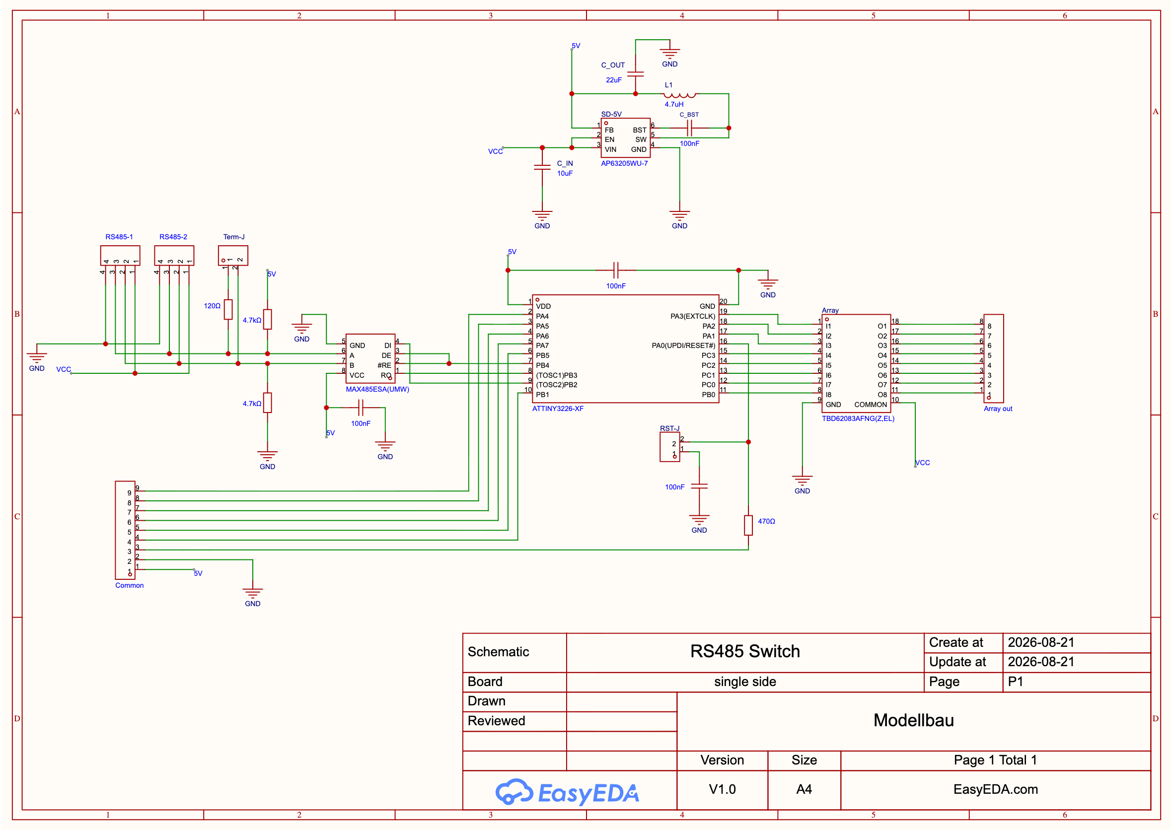
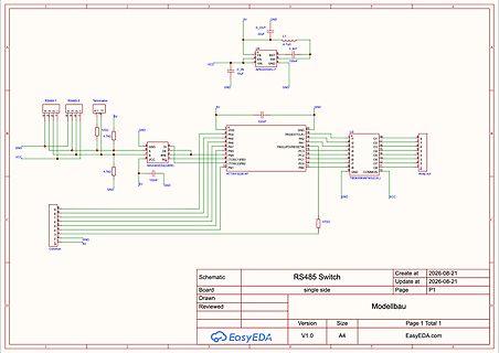
COMMON GND VCC TBD62083AFNG(Z,EL) RS485 Switch Create at 2026-08-21 Update at 2026-08-21 Board single side Page P1 Drawn Modellbau Version V1.0 Size A4 Page 1 Total 1 EasyEDA.com
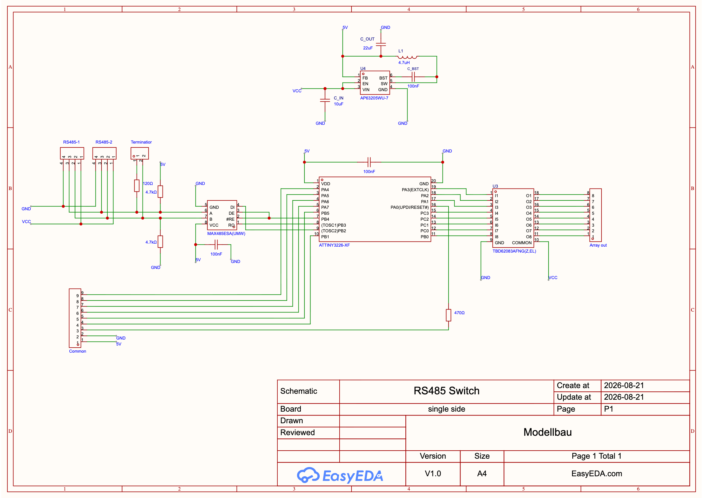
Array out COMMON VCC Schematic RS485 Switch Create at 2026-08-21 Update at 2026-08-21 Board single side Page P1 Drawn Modellbau Page 1 Total 1 Version V1.0 Size A4 EasyEDA.com
für die Dauer des Firmware Updates zum schweigen bringen. Erste Idee: der GPS Sender wird low side mit einem ULN2003A abgeschaltet. Vcc bleibt drann. => kann das funktionieren? oder können da Pegel auftreten, welche der NEO-6M nicht so mag und ich einen Hardwareschaden riskiere? Zur Sicherheit noch
Wemos gesteuert wird und den Verstärker + Boost-Wandler freischaltet. - Oder ein einzelner High-Side-Switch, der die komplette Last (5 V + Verstärker) steuert. Was wäre hier die sauberste und energieeffizienteste Lösung? Ich freue mich über Tipps zu: - geeigneten Verstärkern (klein, effizient
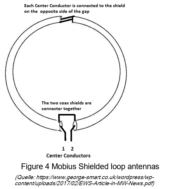
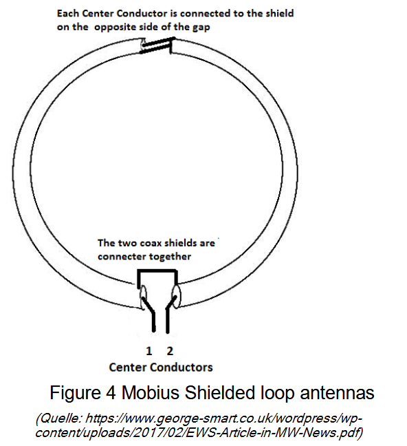
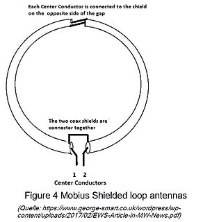
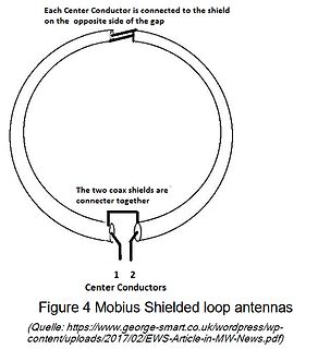
Each Center Conductor is connected to the shield on the opposite side of the gap
The two coax shields are connecter together
1 2
Center Conductors
Figure 4 Mobius Shielded loop antennas
(Quelle: https://www.george-smart.co.uk/wordpress/wp-content/uploads/2017/02/EWS-Article-in-MW-News.pdf
Hausinternetanschlüsse noch nicht so verbreitet waren. Sidux war Rolling Release, basierend auf Sid. Die ausdrücklich vorgesehene Betriebsweise war, regelmäßig Updates zu fahren, weil in Sid nunmal regelmäßig Neuerungen und Änderungen einflossen, die weitestgehend direkt weitergegeben wurden. Entsprechend
Jack V. schrieb im Beitrag #8092928: > Sidux war Rolling Release, basierend auf Sid. Die ausdrücklich > vorgesehene Betriebsweise war, regelmäßig Updates zu fahren, weil in Sid > nunmal regelmäßig Neuerungen und Änderungen einflossen, die > weitestgehend direkt weitergegeben
Heat-Sink ist. Beim Low-Side MOSFET ist daher die Heat-Sink die Switch-Node, also der Teil, der sehr schnell hohe Spannungen schaltet. In allen Design-Regeln steht, dass diese Switch-Node möglichst klein gehalten werden soll. Gleichzeitig
hat Infineon auch erkannt und deswegen das Source-Down-Package entwickelt. Du kannst für den High-Side-Schalter einen Drain-Down verwenden und für den Low-Side einen Source-Down, damit wird das Problem elegant umgangen. Dafür käme beispielsweise der hier infrage https://www.infineon.com/part/IQE030N06NM5
connector uses a standard IEEE-488 pinout. Back view 2 3 (2) Status LED (3) Firmware update button Side view 4 (4) USB-Type C connector – plug it with either a USB Type C to USB type A or USB type C to type C cable into your PC. Page | 5 LED The LED has multiple purposes as summarized in the table below
gibt unterschiedlichste Varianten mit und ohne Gewinde. ### Infineon BTS80009-SWPF-1ES – High Side-Switch für bis zu 34.5A Wer einen intelligenten High Side-Switch sucht, wird bei Infineon mit einer neuen SKU bedient. Hervorzuheben ist die weitgehende Einstellbarkeit, die die Absicherung der geschalteten
–13 Mounting the Raised Display Unit on the Short Side of the Scale First, decide whether you want to mount the display on the short side or on the back (long side) of the scale. ! Please follow the instructions given on page1–12 before you begin to change
Each Center Conductor is connected to the shield on the opposite side of the gap
The two coax shields are connecter together
1 2
Center Conductors
Figure 4 Mobius Shielded loop antennas
(Quelle: https://www.george-smart.co.uk/wordpress/wp-content/uploads/2017/02/EWS-Article-in-MW-News.pdf
fixed conveyor side for conveyor track 2 (in example of S-27 HM) Key (1) Fixed side - conveyor track 1 (4) Fastening screw (2) Fixed side - conveyor track 2 (5) Moving the fixed side - conveyor track 2 (3) Side flange
#8077236: > 1.) Der HD2AD100T --> Müsste wohl irgend ein Gate Treiber sein, oder? > Sind ein High Side und ein Low Side Mosfet in der nähe https://www.onsemi.com/download/data-sheet/pdf/fan3100t-d.pdf
schrieb: >> 1.) Der HD2AD100T --> Müsste wohl irgend ein Gate Treiber sein, oder? >> Sind ein High Side und ein Low Side Mosfet in der nähe > > https://www.onsemi.com/download/data-sheet/pdf/fan3100t-d.pdf Treffer!
Manual, Rev. N
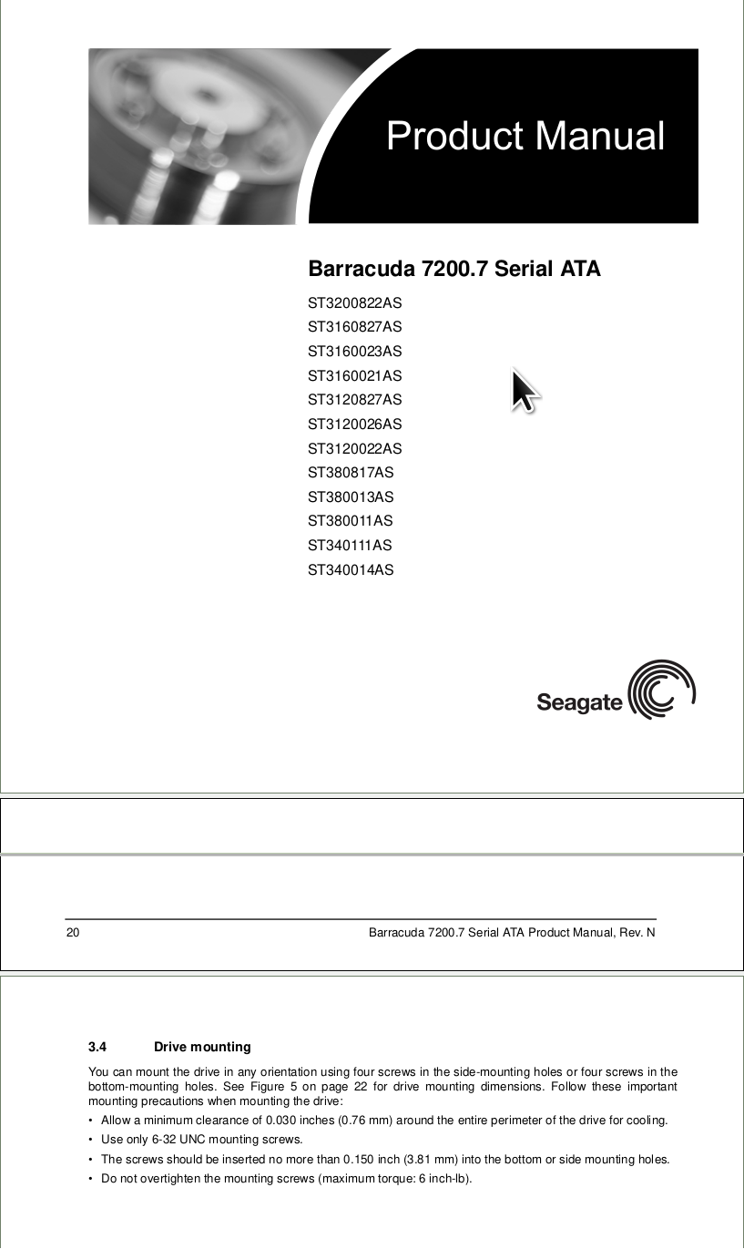
3.4 Drive mounting
You can mount the drive in any orientation using four screws in the side-mounting holes or four screws in the bottom-mounting holes. See Figure 5 on page 22 for drive mounting dimensions. Follow these important mounting precautions when mounting the drive:
• Allow a minimum
you what to do. 2.1 Miscellaneous voltages LocateandidentifyaMolex8poleconnectorJ1002(attheinner side of the vertical rear chassis) where an 8 pole ribbon cable coming from the MB board is connected. See photo 2.1. 2.1 All voltages are measured with respect to ground (chassis). The following voltages
C Dimensions – Millimeters Loose Insulated Rigid Leads Insulated Flexible Leads 0.5 mm FRONT VIEW SIDE VIEW FRONT VIEW SIDE VIEW FRONT VIEW SIDE VIEW L T L T L T H H H S F LL 5 0 ± 5 5 3 1 ± ± F 8 8 S T H L F Nominal Tolerance Nominal Tolerance Nominal Tolerance Nominal Tolerance Nominal Tolerance 10.0
dazu kommen, warum dann nicht einen Gate Treiber als Pegelwandler missbrauchen? Gut ich brauch High side, aber sollte doch prinzipiell funktionieren? Das wäre dann nur ein Bauteil. https://www.infineon.com/assets/row/public/documents/24/49/infineon-irs10752l-datasheet-en.pdf Im Prinzip suche ich
also nicht reichen sollte, gibt es auch zahlreiche automotive-qualified Rundum-Sorglos-Smart-High-Side-Powerswitch-ICs, die genau für Deinen Anwendungsfall entworfen wurden, z.B. BTS462 oder seine Artgenossen. HTH (re)
for the The InnoSwitch3-EP combines a high-voltage power switch, along controller on the secondary-side and provide secondary protection. with both primary-side and secondary-side controllers in one device. FORWARD (FWD) Pin (Pin 7) The architecture incorporates a novel inductive coupling feedback The
Each Center Conductor is connected to the shield on the opposite side of the gap
The two coax shields are connecter together
1 2
Center Conductors
Figure 4 Mobius Shielded loop antennas
(Quelle: https://www.george-smart.co.uk/wordpress/wp-content/uploads/2017/02/EWS-Article-in-MW-News.pdf
in der Schaltung sein? Links ist die Batterie angeklemmt und rechts die Last also typischer high side Schalter. Er leitet wenn die Gatespannung niedriger ist als die Sourcespannung abzüglich der Gate Threshold Spannung ist und das ist ja der Fall, wenn das Gate über den Pulldown Widerstand auf Masse
channels, optional ADC pin 1 group of OPA and comparator: PGA 2-group analog voltage comparator CMP: - P-side supports 3-channel polling connected with ADC and TIM2 CMP - Support high-speed mode to increase swing rate - General-purpose CMP, 3 input channels, supports 3 CMP polling to detect positioning and
programmer with UART connection • PowerIO Shield - Extended power capabilities with six 3A high-side switches at up to 48V • Arduino headers - Compatible with a wide range of Arduino shields and accessories [/c] Unter https://mercedes-benz.github.io/ardep/samples/uds/README.html findet sich
145dB (TYP) The rail-to-raioutput swing provided by the • CMRR: 125dB (TYP) SGMOP17C makes both high-side and low-side • 0.1Hz to 10Hz Noise: 1μV P-P sensing easy. The combination of characteristics • 56nV/ Hz Voltage Noise Density at 1kHz makes the SGMOP17C good choice for temperature, • Gain-Bandwidth
www.rflambda.com/product/amplifiers/acamplifier/REMC18G40GD ### ams OSRAM SFH 4256B & SFH 4244B – Side-LEDs für Infrarot Infrarotemitter sind oft am “Rand” der Platine am Vernünftigsten. Seitlich montierbare Leuchtdioden sparen hier Komplexität (und zusammengelötete Platinen, man denke an die DOLCH-Logikanalysatoren
E3630 Series Power Supplies Agilent E3631A/32A/33A/34A E3631A 80-Watt To rackmount two instruments side-by-side Lock-link Kit (P/N 5061-9694) Triple Power Supply E3632A 120-Watt Flange Kit (P/N 5063-9214) Single Power Supply To rackmount one or two instruments in a E3633A/34A 200-Watt sliding support
running at 8-A continuous output, and left for a period of time to come to thermal equilibrium. The top-side plot was recorded from above while the bottom was recorded from below, looking up. Figure 16. Layout 1 - Single Sided, All Components Top Side Figure 17. Layout 2 – Double Sided, Inductor Top Side, IC Bottom Side Figure 18. Layout 3 – Double Sided, Inductor Top Side, IC Bottom Side 8 Reduced Size, Double-Sided Layout for High-Current DC/DC Converters SLVA963–April 2018 Submit Documentation Feedback Copyright
connect a power supply for the antenna unit and has a standard Ethernet port on the controller/display side. Fig. 2 A typical installation as provided by the manufacturer [5]. The optional Navico Expansion Port is a common Ethernet switch. 4 Adrian Dabrowski, Sebastian Busch and Roland Stelzer 4 Methods for
inductive loads. 92/125 L9805E On-chip peripherals 5.8.2 Main features The nominal current is 2A. The low-side switch is a n-channel DMOS transistor while the high-side switch is a p- channel DMOS transistor. Therefore no charge pump is needed. An anti-crossconduction circuit is included: the low side DMOS is

 Bild
 Bild

 Bild
 Bild
 Bild
 Bild
 Bild
 Bild
 Bild

 Bild