-
Datei
20230502-d-chatgpt.ino
// Pin-Definitionen const int zeroCrossingPin = 2; // Pin für Nulldurchgang const int outputPin = 7; // Pin für Ausgabe // Variablen für die Einstellungen int FLANKENKORREKTUR = 300; // Korrekturwert in Mikrosekunden int pulseWidth = 8000; // Länge des HIGH-Pulses in Mikrosekunden int pulsePosition = 1000; // Position des HIGH-Pulses in Prozent der Halbwelle // Variablen für den Interrupt volatile boolean zeroCrossing = false; volatile unsigned long zeroCrossingTime = 0; void setup() { // Flankenkorrektur pulsePosition = pulsePosition + FLANKENKORREKTUR, // Pin-Modi setzen pinMode(zeroCrossingPin
in „Eigenbau Solarwechselrichter (diy grid tie inverter)“ · Haus & Smart Home ·
-
Datei
20230502a-solarinverter.ino
// Solarwechselrichter de dd3et // https://www.etechnophiles.com/how-to-change-the-pwm-frequency-of-arduino-nano/ // TCCR2B = TCCR2B & B11111000 | B00000001; // for PWM frequency of 31372.55 Hz on D3 & D11 // https://www.arduino.cc/reference/de/language/functions/external-interrupts/attachinterrupt/ // https://www.mikrocontroller.net/topic/542674?page=3#7218665 // Widerstand int widerstandspin = 12; bool widerstand; int pvspgpin = A0; int pvspg; // Nulldurchgang // Variablen für die Einstellungen int flankenkorrektur = 300; // Korrekturwert in Mikrosekunden mit Oszilloskop ermitteln int pulslaenge
in „Eigenbau Solarwechselrichter (diy grid tie inverter)“ · Haus & Smart Home ·
-
Datei
test3.2.ino
#include <WiFi.h> #include <FirebaseESP32.h> //#include <DHT.h> #include <NTPClient.h> #include <WiFiUdp.h> #include <IRremoteESP8266.h> #include <IRrecv.h> #include <IRutils.h> #define WIFI_SSID "Herech" #define WIFI_PASSWORD "here" #define FIREBASE_HOST "http://here.firebasedatabase.app/" #define FIREBASE_AUTH "AIherelM" const int RECV_PIN = 14; IRrecv irrecv(RECV_PIN); decode_results results; int digit; int debounceDelay = 100; // Debounce delay in milliseconds int Timeout = 2000; // Number entry timeout in milliseconds unsigned long lastKeyTime = 0; const String channelsName[50] = {"BBC",
in „ESP32 Automatic Reset after one cycle“ · Mikrocontroller und Digitale Elektronik ·
-
Datei
Arduino_Drehzahlmesser_01.ino
#include <LiquidCrystal_I2C.h> #include <Wire.h> LiquidCrystal_I2C lcd(0x27,16,2); // set the LCD address to 0x27 for a 16 chars and 2 line display. ACHTUNG: Adresse kann auch 0x3F sein !!! // Anschlüsse: // GND - GND // VCC - 5V // SDA - ANALOG Pin 4 // SCL - ANALOG pin 5 int sensor = 2; unsigned long currentTime; unsigned long lastTime; //unsigned long pulse_freq; unsigned long period; float pulse_freq; // =========================== // ======= SETUP ========= // =========================== void setup() { pinMode(sensor, INPUT); Serial.begin(9600); attachInterrupt(0, pulse, FALLING); // Setup Interrupt
in „Physikprojekte“ · Offtopic ·
-
Datei
Arduino_Drehzahlmesser_02.ino
#include <LiquidCrystal_I2C.h> #include <Wire.h> LiquidCrystal_I2C lcd(0x27,16,2); // set the LCD address to 0x27 for a 16 chars and 2 line display. ACHTUNG: Adresse kann auch 0x3F sein !!! // Anschlüsse: // GND - GND // VCC - 5V // SDA - ANALOG Pin 4 // SCL - ANALOG pin 5 int sensor = 2; unsigned long currentTime; unsigned long lastTime; unsigned long pulse_freq; // =========================== // ======= SETUP ========= // =========================== void setup() { pinMode(sensor, INPUT); Serial.begin(9600); attachInterrupt(0, pulse, FALLING); // Setup Interrupt currentTime = millis(); lastTime
in „Physikprojekte“ · Offtopic ·
-
Datei
Arduino_Anemometer_02.ino
#include <LiquidCrystal_I2C.h> #include <Wire.h> LiquidCrystal_I2C lcd(0x27,16,2); // set the LCD address to 0x27 for a 16 chars and 2 line display. ACHTUNG: Adresse kann auch 0x3F sein !!! // Anschlüsse: // GND - GND // VCC - 5V // SDA - ANALOG Pin 4 // SCL - ANALOG pin 5 int sensor = 2; unsigned long currentTime; unsigned long lastTime; unsigned long period; unsigned long time_passed_min; unsigned long pulse_freq; unsigned long oldTime; float velocity; // =========================== // ======= SETUP ========= // =========================== void setup() { pinMode(sensor, INPUT); Serial.begin(9600
in „Physikprojekte“ · Offtopic ·
-
Datei
RTC_DS3231.ino
/* * RTC DS3231 via I2C * IO 13 for power supply */ #include <Wire.h> #define RTC_I2C_ADR 0x68 // 7 bit mode! #define MODE_AM 0 #define MODE_PM 1 #define MODE_24H 2 uint8_t rtc_buffer[19]; const char dow[7][10] = {"Monday", "Tuesday", "Wednesday", "Thursday", "Friday", "Saturday", "Sunday"}; void writeRegister(uint8_t address, uint8_t data) { Wire.beginTransmission(RTC_I2C_ADR); Wire.write(address); Wire.write(data); Wire.endTransmission(true); } uint8_t readRegister(uint8_t address) { uint8_t tmp; Wire.beginTransmission(RTC_I2C_ADR); Wire.write(address); Wire.endTransmission(true); Wire.requestFrom(RTC_I2C_ADR
in „DS3231SN RTC Module mit DS3231M (MEMS) Typ installiert“ · Mikrocontroller und Digitale Elektronik ·
-
Datei
Encoder_PeDa_Original.ino
#include <Arduino.h> /************************************************************************/ /* */ /* Reading rotary encoder */ /* one, two and four step encoders supported */ /* */ /* Author: Peter Dannegger */ /* target: ATmega16 */ /************************************************************************/ #include <avr/io.h> #include <avr/interrupt.h> //#define XTAL 8e6 // 8MHz #define F_TIMER1 100 // Timer 1 frequency /Hz #define ENCODER_PIN PINC #define PHASE_A (1<<PC2) #define PHASE_B (1<<PC4) #define LEDS_DDR DDRF #define LEDS PORTF // LEDs against VCC volatile int8_t enc_delta; // static
in „Peter Dannegger´s ( PeDa ) Entprellroutine in ein Arduino Sketch einbinden“ · Mikrocontroller und Digitale Elektronik ·
-
Datei
Encoder_PeDa_Original.ino
#include <Arduino.h> /************************************************************************/ /* */ /* Reading rotary encoder */ /* one, two and four step encoders supported */ /* */ /* Author: Peter Dannegger */ /* target: ATmega16 */ /************************************************************************/ #include <avr/io.h> #include <avr/interrupt.h> //#define XTAL 8e6 // 8MHz #define F_TIMER1 100 // Timer 1 frequency /Hz #define ENCODER_PIN PINC #define ENCODER_PORT PORTC #define ENCODER_DDR DDRC #define PHASE_A (1<<PC2) #define PHASE_B (1<<PC4) #define LEDS_DDR DDRF #define LEDS PORTF
in „Peter Dannegger´s ( PeDa ) Entprellroutine in ein Arduino Sketch einbinden“ · Mikrocontroller und Digitale Elektronik ·
-
Datei
h_encoder_falk.ino
#include <Arduino.h> /************************************************************************/ /* */ /* Reading rotary encoder */ /* one, two and four step encoders supported */ /* */ /* Author: Peter Dannegger */ /* target: ATmega16 */ /************************************************************************/ #include <avr/io.h> #include <avr/interrupt.h> //#define XTAL 8e6 // 8MHz #define F_TIMER1 100 // Timer 1 frequency /Hz #define H_ENCODER_PIN PINC #define H_ENCODER_PORT PORTC #define H_ENCODER_DDR DDRC #define H_ENCODER_A ( 1<<PC2 ) #define H_ENCODER_B ( 1<<PC4 ) #define LEDS_DDR DDRF
in „Peter Dannegger´s ( PeDa ) Entprellroutine in ein Arduino Sketch einbinden“ · Mikrocontroller und Digitale Elektronik ·
-
Datei
MIN_MAX_pendeln.ino
#define MAX 210 #define MIN 200 #define AUF_AB ( 1<<0 ) #define SCHRITTWEITE 1 uint8_t flagRegister = 0; uint16_t ocr3a = MAX; void setup() { Serial.begin( 9600 ); } // Ende void setup() void loop() { /////////////////////////////////////////////////////////////////////////////// // Zwischen MIN und MAX pendeln // uint16_t x; x = ocr3a; // Aufwaertszaehlen solange MAX nicht erreicht und Flag auf Aufwaerts steht if( x < MAX && flagRegister & AUF_AB ) { ocr3a += SCHRITTWEITE; ///* Serial.print ( "x < MAX = " ); Serial.println( ocr3a ); //*/ } // MAX-Wert ist erreicht Flag auf Abwaerts stellen else
in „Bitte um Hilfe bei der Programmierung von AVR8-Mikrocontrollern in C“ · Mikrocontroller und Digitale Elektronik ·
-
Datei
ZeitmesserV4.ino
#include "heltec.h" #include <WiFi.h> #define DISPLAY_WIDTH 128 #define DISPLAY_HEIGHT 64 #define IMPULSE_DURATION 1000 // Dauer des Impulses in Millisekunden (1000ms) #define IMPULSE_OUTPUT 2 // GPIO-Pin für den Impuls #define POTI_PIN 1 // GPIO-Pin für das Poti #define MEASUREMENT_DELAY 500 // Verzögerung für die Messung von min und max RSSI in Millisekunden #define RESET_DELAY 500 // Verzögerung für das Zurücksetzen der minimalen und maximalen RSSI-Werte const char* ssid = "Mugen MBX8"; const char* password = "12345678"; int rssiValues[DISPLAY_WIDTH] = {0}; // Array für RSSI-Werte int currentIndex
in „Rundenzeitmesser auf Basis RSSI für RC Fernsteuerung“ · Mikrocontroller und Digitale Elektronik ·
-
Datei
NHD_2_7.ino
#define OLED_DC 49 //Register Select signal #define OLED_RESET 48 //Reset signal #define OLED_CS 47 //Chip select signal #define OLED_CLK 52 //Serial clock signal #define OLED_MOSI 51 //Serial data signal /**************************************************** * Hex Table for Image Pic * *****************************************************/ unsigned char NHD_Logo [] = { 0x00, 0x00, 0x00, 0x00, 0x00, 0x00, 0x00, 0x00, 0x00, 0x00, 0x00, 0x00, 0x00, 0x00, 0x00, 0x00, 0x00, 0x00, 0x00, 0x00, 0x00, 0x00, 0x00, 0x00, 0x00, 0x00, 0x00, 0x00, 0x00, 0x00, 0x00, 0x00, 0x00, 0x00, 0x00, 0x00, 0x00, 0x00,
in „NHD-2.7-12864WDW3 mit SSD1322 - Grayscale Problem“ · Mikrocontroller und Digitale Elektronik ·
-
Datei
PicoTerm-demo.ino
/* PicoTerm-demo zur Ansteuerung der PicoTerm-TFT Anzeige mit Text und Grafik zur Verwendung auf Arduino uno oder anderer Hardware mit ATmega328. Reines C-Programm ohne spezifische Befehle der Arduino-IDE Das Programm gliedert sich in folgende Bereiche: 1. Parametervorgabe/Init für ATmega mit UART und Timer 2. Definitionen fuer Farbe/Text/Grafik des TFT 3. Initialisierung des ATmega328 4. Basisroutinen zur TFT-Ansteuerung 5. Routinen zur Anzeige von Text und Demo-Tastatur 6. Demoprogramm unter Verwendung der vorhandenen Funktionen Michael Nowak www.mino-elektronik.de info@mino-elektronik.de 2023
in „PicoTerm-TFT, farbiges 4,3"-Terminal mit Pico-Board RP2040“ · Projekte & Code ·
-
Datei
Slave_Transmitter_ADC.ino
#include <util/twi.h> int main(){ init(); Serial.begin(9600); // Slave Adresse uint8_t SLA_W = 0b00000110; TWAR = SLA_W; Serial.println("Adresse:"); Serial.println(TWAR, BIN); // Slave aktivieren, ACK fuer eigene Adresse vorbereitet TWCR |= (1 << TWINT); //TW-Interrupt rücksetzen | 0 ist low Zustand TWCR |= (1 << TWEA); //TW-Enable Acknowledge Bit -> ACK wird gesendet wenn: eigene Slave Adresse Empfangen wurde | Daten empfangen wurden | General Call TWCR |= (1 << TWEN); //TW-Enable setzen uint8_t Tank_out = 56; //Variable für das zu sendende Datenpaket while (1) { Serial.println("---"); // Warten
in „Arduino I2C Hardware Register Adressen im MR-ST“ · Mikrocontroller und Digitale Elektronik ·
-
Datei
ESP8266_Test.ino
// the setup function runs once when you press reset or power the board void setup() { // initialize digital pin LED_BUILTIN as an output. pinMode(D7, OUTPUT); // oder : pinMode(LED_BUILTIN, OUTPUT); oder : pinMode(2, OUTPUT); pinMode(D6, INPUT); pinMode(LED_BUILTIN, OUTPUT); digitalWrite(D7, LOW); } // the loop function runs over and over again forever void loop() { digitalWrite(LED_BUILTIN, HIGH); // Lampe aus while(digitalRead(D6) == LOW) yield; digitalWrite(LED_BUILTIN, LOW); for (int i=0; i<8; i++) { digitalWrite(D7, HIGH); delay(20); digitalWrite(D7, LOW); delay(20); } delay(500); }
in „Seltsames Verhalten bei Arbeit mit LevelShifter“ · Mikrocontroller und Digitale Elektronik ·
-
Datei
Laufschrift_08_vereinfacht.ino
// Test DCC-Decoder #include "DCC_Decoder.h" // DCC-Decoder: byte Speed = 0; byte dccRichtung = 0; byte dccCount = 0; // DCC-Adresse: byte dccAdresse = 0; // DCC-Decoder #define kDCC_INTERRUPT 0 typedef struct { int count; byte validBytes; byte data[6]; } DCCPacket; // The DCC-Decoder object and global data int gPacketCount = 0; int gIdlePacketCount = 0; int gLongestPreamble = 0; DCCPacket gPackets[25]; // ALL packets are sent to the RawPacket handler. // Returning true indicates that packet was handled. // DCC library starts watching for next preamble. // Returning false and library continue parsing
in „Problem Arduino Sketch“ · Mikrocontroller und Digitale Elektronik ·
-
Datei
20220921b-Einspeise.ino
// Einspeisewechselrichter // Nulldurchgang int nulldurchgangspin = A5; bool nulldurchgang; bool nulldurchgangvorher; bool nulldurchgangflanke; // Testpins int ledpin = 13; void setup() { pinMode(ledpin,OUTPUT); } void loop() { nulldurchgang = (analogRead(nulldurchgangspin) < 40); //digitalWrite(ledpin, nulldurchgang); // Flanke nulldurchgangflanke = ((nulldurchgang != nulldurchgangvorher) && (nulldurchgangvorher == LOW)); nulldurchgangvorher = nulldurchgang; digitalWrite(ledpin, nulldurchgangflanke); }
-
Datei
20220921c-Einspeise.ino
// Einspeisewechselrichter // Nulldurchgang int nulldurchgangspin = A5; bool nulldurchgang; bool nulldurchgangvorher; bool nulldurchgangflanke; #define EXTINT0 2 // Testpins int ledpin = 13; int testpin =12; void setup() { pinMode(ledpin,OUTPUT); pinMode(testpin,OUTPUT); pinMode(EXTINT0,INPUT); attachInterrupt(digitalPinToInterrupt(EXTINT0), EXTINT0_ISR, FALLING); } volatile bool test; void EXTINT0_ISR() { test = true; } void loop() { nulldurchgang = (analogRead(nulldurchgangspin) < 40); //digitalWrite(ledpin, nulldurchgang); // Flanke nulldurchgangflanke = ((nulldurchgang != nulldurchgangvorher) && (nulldurchgangvorher
-
Datei
20220921d-Einspeise.ino
// Einspeisewechselrichter // Nulldurchgang int nulldurchgangspin = A5; bool nulldurchgang; bool nulldurchgangvorher; bool nulldurchgangflanke; #define EXTINT0 2 // Testpins int ledpin = 13; int testpin =12; void setup() { pinMode(ledpin,OUTPUT); pinMode(testpin,OUTPUT); pinMode(EXTINT0,INPUT); attachInterrupt(digitalPinToInterrupt(EXTINT0), EXTINT0_ISR, FALLING); } volatile bool test; void EXTINT0_ISR() { test = true; } unsigned long nulltime,oldtime; void loop() { nulldurchgang = (analogRead(nulldurchgangspin) < 40); //digitalWrite(ledpin, nulldurchgang); // Flanke nulldurchgangflanke = ((nulldurchgang
-
Datei
20220922d-Einspeise.ino
// Einspeisewechselrichter // UVLO unsigned long netzist; unsigned long netzstart; bool netz; bool uvlonetz; // Nulldurchgang int nulldurchgangspin = A5; bool nulldurchgang; bool nulldurchgangvorher; bool nulldurchgangflanke; // Frequenzbegrenzung nach oben unsigned long ista; unsigned long starta; unsigned long ausvza = 8800; bool nulldurchganga; bool nulldurchgangavorher; bool nulldurchgangaflanke; // dc-dc-Converter Start unsigned long istb; unsigned long startb; unsigned long ausvzb = 2500; bool nulldurchgangb; bool nulldurchgangbvorher; bool dcdcstart; unsigned long istc; unsigned long startc
-
Datei
20221003a-Einspeise.ino
// Einspeisewechselrichter int lpumppin = 11; int dcdcanpin = 7; int modulationspin = 3; // OVLO mit Auszeit int drainpin = A1; int dcdcauspin = 4; unsigned long drainist; unsigned long drainstart; unsigned long drainvz = 10000; int drainwert = 730; // 1023*95V*3K9:(100K + 3K9):5V bool drain; bool ovlodrain; bool dcdcaus; // UVLO Batterie mit Hysterese int battpin = A0; unsigned long battist; unsigned long battstart; int battwerthoch = 464; // 1023*11V*39K:(150K + 39K):5V int battwerttief = 378; // 1023*9V0*39K:(150K + 39K):5V int battwertovlo = 676; // 1023*16V*39K:(150K + 39K):5V int battwert; bool
-
Datei
PowerReglerDTZ.ino
/** * Power Regler DTZ * Version 0.09 * 07.10.2022 P. Rebesky * author Creator P.Rebesky * Copyright (©): 2020-2022 by Peter Rebesky * This code can use in private cases only. Every business or companies using of this codes or codes parts is required an approval of us (me) * Every private using can exchange some parts of code or modify some code-lines. This code is allowed change for private use only. * This software is basicly owned by Peter Rebesky and any comercial using is forbidden without approval of us (me). **/ //#define DEBUG_PAYLOAD //#define DEBUG_VALUE #define OTA_on #include <ESP8266WiFi.h
in „Schaltsteckdose für StromLog ESP“ · Mikrocontroller und Digitale Elektronik ·
-
Datei
20221009b-Einspeise.ino
// Einspeisewechselrichter // https://www.etechnophiles.com/how-to-change-the-pwm-frequency-of-arduino-nano/ // TCCR2B = TCCR2B & B11111000 | B00000001; // for PWM frequency of 31372.55 Hz on D3 & D11 int lpumppin = 11; int dcdcanpin = 7; int modulationspin = 3; // OVLO mit Auszeit int drainpin = 6; int dcdcauspin = 4; unsigned long drainist; unsigned long drainstart; unsigned long drainvz = 10000; bool drain; bool ovlodrain; bool dcdcaus; // UVLO Batterie mit Hysterese int battpin = A0; unsigned long battist; unsigned long battstart; int battwerthoch = 464; // 1023*11V*39K:(150K + 39K):5V int
-
Datei
20221011a-Einspeise.ino
// Einspeisewechselrichter // https://www.etechnophiles.com/how-to-change-the-pwm-frequency-of-arduino-nano/ // TCCR2B = TCCR2B & B11111000 | B00000001; // for PWM frequency of 31372.55 Hz on D3 & D11 int lpumppin = 11; int dcdcanpin = 7; int modulationspin = 3; // OVLO mit Auszeit int drainpin = 6; int dcdcauspin = 4; unsigned long drainist; unsigned long drainstart; unsigned long drainvz = 10000; bool drain; bool ovlodrain; bool dcdcaus; // UVLO Batterie mit Hysterese int battpin = A0; unsigned long battist; unsigned long battstart; int battwerthoch = 464; // 1023*11V*39K:(150K + 39K):5V int
-
Datei
LoRa_Sender.ino
/*** LoRa-Geraffel ***/ #include <TTN_esp32.h> // For Testing/TestApplication, set to your Values!!! const char* devEui = "7788998877665544"; const char* appEui = "7788998877665544"; const char* appKey = "494136c46837032fd41a9cda30d51e33"; TTN_esp32 ttn ; /*** LoRa End ***/ /*** Display ***/ #include "heltec.h" #define __USE_DISPLAY 1 // 0 = Display Off, 1 = Display On, 2 = Display On only on first Boot after Restart or Reset /*** Display End ***/ /*** Batteriegeraffel ***/ #include <Arduino.h> #include <esp_adc_cal.h> #include <driver/adc.h> #define MAXBATT 4200 // The default Lipo is 4200mv when
in „Digitale Stromzähler auslesen und in DB speichern“ · Mikrocontroller und Digitale Elektronik ·
-
Datei
PowerReglerDTZ.ino
/** * Power Regler DTZ * Version 0.20 * 19.10.2022 P. Rebesky * author Creator P.Rebesky * Copyright (©): 2020-2022 by Peter Rebesky * This code can use in private cases only. Every business or companies using of this codes or codes parts is required an approval of us (me) * Every private using can exchange some parts of code or modify some code-lines. This code is allowed change for private use only. * This software is basicly owned by Peter Rebesky and any comercial using is forbidden without approval of us (me). **/ //#define DEBUG //#define DEBUG_PAYLOAD //#define DEBUG_VALUE //#define DEBUG_CONNECT
in „Schaltsteckdose für StromLog ESP“ · Mikrocontroller und Digitale Elektronik ·
-
Datei
AssemblerTestMinimal.ino
// #include "main.h" // Nur wenn ASM Dinge in der C++ Abteilung aufgerufen werden wollen
in „welche Chips sind ähnlich leicht zu programmieren wie die ATMEL-Chips ?“ · Mikrocontroller und Digitale Elektronik ·
-
Datei
20221024a-Einspeise.ino
// Einspeisewechselrichter de dd3et // https://www.etechnophiles.com/how-to-change-the-pwm-frequency-of-arduino-nano/ // TCCR2B = TCCR2B & B11111000 | B00000001; // for PWM frequency of 31372.55 Hz on D3 & D11 // https://www.arduino.cc/reference/de/language/functions/external-interrupts/attachinterrupt/ // https://www.mikrocontroller.net/topic/542674?page=3#7218665 // OVLO mit Auszeit int drainpin = 6; unsigned long drainist; unsigned long drainstart; unsigned long drainvz = 10000; bool drain; bool ovlodrain; // UVLO Batterie mit Hysterese int elkoladepin = 5; int battpin = A0; unsigned long battist
-
Datei
StromLog_Open.ino
/** * Main StromLog * Version 5.01 * 20.11.2022 P. Rebesky * author Creator P.Rebesky * Copyright (©): 2022-2024 by Peter Rebesky * This code can use in private cases only. Every business or companies using of this codes or codes parts is required an approval of us (me) * Every private using can exchange some parts of code or modify some code-lines. This code is allowed change for private use only. * This software is basicly owned by Peter Rebesky and any comercial using is forbidden without approval of us (me). **/ //#define crc16check #define OTA_on #include <ESP8266WiFi.h> //ESP8266 Core WiFi Library
in „Digitale Stromzähler auslesen und in DB speichern“ · Mikrocontroller und Digitale Elektronik ·
-
Datei
Arduino_Bluetooth_Smartphone.ino
#include<SoftwareSerial.h> SoftwareSerial BT(0,1); // 0 = RX, 1 = TX void setup() { // put your setup code here, to run once: BT.begin(9600); } void loop() { for (int i = 1; i < 10;i++) { BT.print(i * 0.5); BT.print(","); BT.print(126); BT.print(";"); delay(500); } }
in „Physikprojekte“ · Offtopic ·
-
Datei
RP2040-test.ino
#include <Arduino.h> #include <hardware/dma.h> uint32_t dma_dummy, PWM_CH2_event; // Zeitstempel erzeugen: // DMA-Wert = Zeitpunkt, DMA-TRANS-COUNT = Ereignisse void init_dma_pio0(void) { RESETS_CLR->RESET = RESETS_RESET_dma_Msk | RESETS_RESET_busctrl_Msk; while (!(RESETS->RESET_DONE & RESETS_RESET_dma_Msk)); BUSCTRL->BUS_PRIORITY = BUSCTRL_BUS_PRIORITY_DMA_W_Msk | BUSCTRL_BUS_PRIORITY_DMA_R_Msk; // PIO0_SM0 DMA->CH0_READ_ADDR = (uint32_t) &PWM->CH2_CTR; // capture CH2-CTR DMA->CH0_WRITE_ADDR = (uint32_t) &PWM_CH2_event; // DMA->CH0_TRANS_COUNT = 1; DMA->CH0_CTRL_TRIG = DREQ_PIO0_RX0 << DMA_CH1_CTRL_TRIG_TREQ_SEL_Pos
in „RP2040 C-Programm mit Arduino IDE verwenden“ · Mikrocontroller und Digitale Elektronik ·
-
Datei
opa_remote_arduino.ino
#include <IRremote.h> #define BUTTON_PIN_1 2 // Power #define BUTTON_PIN_2 4 // Vol Up #define BUTTON_PIN_3 5 // Vol Down #define BUTTON_PIN_4 6 // DasErste #define BUTTON_PIN_5 7 // ZDF #define BUTTON_PIN_6 8 // BR IRsend irsend(3); void setup() { pinMode(BUTTON_PIN_1, INPUT_PULLUP); pinMode(BUTTON_PIN_2, INPUT_PULLUP); pinMode(BUTTON_PIN_3, INPUT_PULLUP); pinMode(BUTTON_PIN_4, INPUT_PULLUP); pinMode(BUTTON_PIN_5, INPUT_PULLUP); pinMode(BUTTON_PIN_6, INPUT_PULLUP); } void loop() { if (digitalRead(BUTTON_PIN_1) == LOW) { irsend.sendNEC(0x4, 0x8, 0); // Power delay(500); } if (digitalRead(BUTTON_PIN
in „Hilfe: Von Arduino auf Mikrocontroller (Fernbedienung)“ · Mikrocontroller und Digitale Elektronik ·
-
Datei
Arduino_Geigerzaehler_02.ino
#include <LiquidCrystal_I2C.h> #include <Wire.h> LiquidCrystal_I2C lcd(0x27,16,2); // set the LCD address to 0x27 for a 16 chars and 2 line display. ACHTUNG: Adresse kann auch 0x3F sein !!! // Anschlüsse: // GND - GND // VCC - 5V // SDA - ANALOG Pin 4 // SCL - ANALOG pin 5 const int buzzerPin = 9; const int buttonPin = 10; const byte interruptPin = 2; volatile long pulse = 0; volatile long pulse_min = 0; long time_sec = 0; long time_min = 0; long time_min_old = 0; long time_hour = 0; long Anzeige_second = 0; long Anzeige_minute = 0; long Anzeige_hour = 0; long millis_reset = 0; int buttonState = 0
in „Physikprojekte“ · Offtopic ·
-
Datei
Geigerzaehler_GC20.ino
/* https://github.com/pra22/GC-20 SBM-20 based Geiger Counter Author: Prabhat Email: pra22@pitt.edu Sketch for ESP8266 that counts clicks from the Geiger tube, calculates the counts per minute, and displays information on a TFT touchscreen. Attribution-ShareAlike 4.0 International (CC BY-SA 4.0) */ #include <Arduino.h> #include <ESP8266WiFi.h> #include <EthernetClient.h> #include <DNSServer.h> #include <ESP8266WebServer.h> #include <WiFiManager.h> #include <EEPROM.h> #include "SPI.h" #include "Adafruit_GFX.h" #include <Fonts/FreeSans9pt7b.h> #include <Fonts/FreeSans12pt7b.h> #include "Adafruit_ILI9341
in „Hilfe 2.8" LCD Problem“ · Mikrocontroller und Digitale Elektronik ·
-
Datei
FILTER_medianQsort.ino
// Algo from Detlef _. (detlef_a) 19.05.2024 20:53 // https://www.mikrocontroller.net/topic/567716#7668204 //typedef float median_t; //typedef int32_t index_t; typedef int16_t median_t; typedef uint8_t index_t; #define NN (11) int cmpfunc (const void* a, const void* b) { return ( *(median_t*)a - *(median_t*)b ); } median_t median(median_t neu) { static index_t idx = 0; static median_t timebased[NN]; static median_t sorted[NN]; timebased[idx++] = neu; idx %= NN; memcpy(sorted, timebased, sizeof(sorted)); qsort(sorted, NN, sizeof(median_t), cmpfunc); return (sorted[(NN - 1) / 2]); } void setup() { Serial.begin
in „Effizienter Running Median“ · Digitale Signalverarbeitung / DSP / Machine Learning ·
-
Datei
RTC_DS3231.ino
/* * RTC DS3231 via I2C * IO 13 for power supply */ #include <Wire.h> #define RTC_I2C_ADR 0x68 // 7 bit mode! #define MODE_AM 0 #define MODE_PM 1 #define MODE_24H 2 uint8_t rtc_buffer[19]; const char dow[7][10] = {"Monday", "Tuesday", "Wednesday", "Thursday", "Friday", "Saturday", "Sunday"}; void writeRegister(uint8_t address, uint8_t data) { Wire.beginTransmission(RTC_I2C_ADR); Wire.write(address); Wire.write(data); Wire.endTransmission(true); } uint8_t readRegister(uint8_t address) { uint8_t tmp; Wire.beginTransmission(RTC_I2C_ADR); Wire.write(address); Wire.endTransmission(true); Wire.requestFrom(RTC_I2C_ADR
in „RTC DS3231 (EOSC) Uhrzeit läuft nicht weiter, nur mit Knopfzelle“ · Mikrocontroller und Digitale Elektronik ·
-
Datei
ReadEncoderAnalog.ino
/* * Kodierschalter mit 16 Stellungen mittels ADC lesen */ #define ADC_PIN A0 #define ADC_OFFSET 512 // Code am ADC, wenn alle Schalter offen sind, Code 0 #define ADC_RANGE 512 // aktiver Messbereich, meistens die Hälfte der Codes #define TEST // Testausgabe aktivieren void setup() { Serial.begin(9600); Serial.println("\r\n\r\n16er Encoder mit ADC lesen"); } int read_encoder(void) { int tmp; tmp = analogRead(ADC_PIN); #ifdef TEST Serial.print("ADC: "); Serial.println(tmp); #endif if (tmp < ADC_OFFSET) tmp = ADC_OFFSET; tmp = (tmp - ADC_OFFSET + (ADC_RANGE/32)); tmp = (tmp * 16 ) / ADC_RANGE; if
in „Arduino Nano, Drehpotentiometer mit Rasten und Endanschlag“ · Mikrocontroller und Digitale Elektronik ·
-
Datei
V3_0.ino
/**************************************************************************************************** *************************************------------------------**************************************** ************************************| Druckzyklensoftware |*************************************** *************************************------------------------**************************************** ************************************| Claf, 15.09.2016 |*************************************** *************************************------------------------**************************************
in „Fragen zu Schaltkreis“ · Analoge Elektronik und Schaltungstechnik ·
-
Datei
CAN1_0.ino
// -------------------------------------- Umbenenen der STM Pins // Bliotheken //------------------------------------------------------------------------------------------------------------Testweise auskommentiert #include <assert.h> #include "stm32f103.h" // Bei selbst erstellten Bibliotheken der name immer in Anführungszeichen!! Nicht in größer kleiner als Zeichen! // EIngänge // Taster const int Taster = PB9; int TasterState = 0; // Ausgänge const int LED = PA0; void setup() { pinMode(LED_BUILTIN, OUTPUT); //LED auf Arduino auf HIGH // -------------------------------------- pinMode pinMode(Taster
in „Arduino Blue Pill & CAN mit SN65HVD230“ · Mikrocontroller und Digitale Elektronik ·
-
Datei
defaults_user_settings.ino
#include <Arduino.h> /* Standard Arduino library */ #include <LittleFS.h> /* Filesystem */ #include <map> #include <set> /***************************************************************** FALLS EINE LED ANGESCHLOSSSEN IST, BITTE HIER DEN PIN ANGEBEN FALLS EINE LED ANGESCHLOSSSEN IST, BITTE HIER DEN PIN ANGEBEN FALLS EINE LED ANGESCHLOSSSEN IST, BITTE HIER DEN PIN ANGEBEN *****************************************************************/ #define LED_PIN D5 class PublicKeyValuePairs { public: // Constructor initializes default keys and reads custom key-value pairs from file PublicKeyValuePairs()
in „Anfänger-Entwicklung einer Gärbox Steuerung“ · Offtopic ·
-
Datei
defaults_user_settings.ino
#include <Arduino.h> #include <LittleFS.h> #define KEY_VALUE_SIZE 50 // #define DEFAULT_VALUES_COUNT 2 #define KEY_VALUE_DELIMITER "__" // #define MAX_2BYTE_CHARS_IN_KV_PAIRS 6 class KeyValuePairs { // Arrays for storing key-value pairs String default_key_values; String runtime_key_values; // Default values initialization string String defaults_for_initialization = "__vorwärm_temperatur __27" "__nachlauf_temperatur __18"; public: // new version of 11.08.24 KeyValuePairs() { /* Initialize LittleFS */ if (!LittleFS.begin()) { // Error condition while (true); // Endless loop } File file = LittleFS.open
in „Anfänger-Entwicklung einer Gärbox Steuerung“ · Offtopic ·
-
Datei
BLE_Keyboard5.ino
/* Bluetooth BLE Keyboard - Deutsches Tastaturlayout (QWERTZ) ESP32 wird per USB an den Sender-PC angeschlossen und sendet Tastenanschlaege per BLE an den Ziel-Rechner. Benutzung mit minicom (Linux) als Sender: minicom -D /dev/ttyUSB0 Hardware: ESP32 WROOM Framework: Arduino ESP32 Bibliotheken: https://github.com/HijelHub/HijelHID_BLEKeyboard https://github.com/h2zero/NimBLE-Arduino 2026-08-17 mchris (Claude support), Version für deutsche Tastatur */ #include <HijelHID_BLEKeyboard.h> HijelHID_BLEKeyboard keyboard("ESP32 Tastatur", "Deutsch", 100); // Sendet einen Unicode-Codepoint so, dass am Host
in „Remote Tastatur“ · Projekte & Code ·
-
Datei
VeluxSender2.ino
// Fernbedienung für Velux WLC100 // LCD/Keypad Shield an D4 D5 D6 D7 D8 D9 und A0 // IR-Sendediode über Treibertransistor an D3 // 16MHz Keramikresonator oder Schwingquarz #include <LiquidCrystal.h> // ============================================================ // Globale Variablen // ============================================================ int m = 1; // welcher Motor des Fensters, 1-3 Manual, 4-6 = 1-3 Auto int f = 0; // welches Fenster, 0=All, 1-10 // ============================================================ // LCD 16x2 Keypad Shield // ==============================================
in „Velux WLC 100 durch Kleinsteuerung ersetzen“ · Haus & Smart Home ·
-
Datei
hp_signal_steuerung.ino
// Signalsteuerung Hp0 / Hp1 / Hp2 / Sh1 // Automatischer Fall auf Hp0 nach 3 Runden (2 Reedkontakte, Gruppensignal) // plus 4 manuelle Taster zur Signalwahl (Hp0 manuell = normaler Haltruf) // Arduino Nano const int S1_PIN = 2; // Reedkontakt 1 const int S2_PIN = 3; // Reedkontakt 2 const int BTN_HP0 = 4; // Taster Hp0 (Halt) const int BTN_HP1 = 5; // Taster Hp1 (Fahrt) const int BTN_HP2 = 6; // Taster Hp2 (Langsamfahrt) const int BTN_SH1 = 7; // Taster Sh1 (Rangierfahrt) const int LED_ROT1 = 8; const int LED_ROT2 = 9; const int LED_GRUEN = 10; const int LED_GELB = 11; const int LED_WEISS1 = 12
in „Lichtschranken-Rundenzähler (12V).“ · Mikrocontroller und Digitale Elektronik ·
-
Datei
morse_esp32.ino
/* * ========================================================================== * Morse-Decoder / Morse-Geber für ESP32 mit SPI-TFT (ILI9341 / ST7735 / ST7789) * ========================================================================== * * Board : AZ-Delivery ESP32 DevKit V4 (ESP32-WROOM-32, ESP32-D0WD-V3, 4 MB Flash) * Display: 1,69" ST7789V2, 240x280 (Pins/Einstellungen aus PlatformIO-Projekt "Test ST7789") * Arduino-Board-Einstellung: "ESP32 Dev Module" (FQBN esp32:esp32:esp32) * * Funktionen * ---------- * DECODER : Morsetaste (Taster gegen GND) an GPIO 27. * - Entprellung in Software * -
in „Mit KI generierter CW-Decoder für ESP32“ · Mikrocontroller und Digitale Elektronik ·
-
Datei
Poti_16_Stufen.ino
/* Die Spannung eines Potis wird mit 16 abgestuften Spanungswerten 0 -> VCC am PWM-Ausgang ausgegeben; dazu muß ein RC-Filter ergaenzt werden. Die Stellung des Potis muß zuvor ueber 80 ms stabil sein und wird mit einer Hysterese ausgewertet, damit der Ausgangswert nicht 'wackelt'. Verwendete Hardware: Arduino UNO mit ATmega328 http://www.mino-elektronik.de Alle Angaben ohne Gewaehr ! 2025-10-17 */ #include <avr/io.h> #include <avr/interrupt.h> #include <stdlib.h> #define BIT(x) (1<<x) #define F_CPU 16000000L // 16MHz ggf. an eff.Frequenz anpassen #define T1_VORTEILER 8 #define PRO_SEKUNDE 100 /
in „Ich möchte aus einer Spannung einen binärcode erzeugen“ · Analoge Elektronik und Schaltungstechnik ·
-
PDF
A7530.pdf
Output current Output Current 9. A7530K3R-401 Ripple Voltage vs. 10. A7530K3R-401 Quiescent Current (Ino load) vs. Output Current Input Voltage REV3.1 - JUN 2007 RELEASED, NOV 2017 UPDATED - - 6 - AiT Semiconductor Inc. A7530 www.ait-ic.com DC-DC CONVERTER BOOST(STEP-UP) HIGH EFFICIENCY LOW NOISE PFM TEST
in „Upconverter für 5V Out - wie Rauschen auf Ausgangsleitung blocken?“ · Analoge Elektronik und Schaltungstechnik ·
-
Datei
countdown_timer_4x7_seg_06092016_mit_Leuchten_pausen..ino.ino
////////////////////////////////Projekt Pressentationsanzeige Stand:___06.09.2016______/////////////////////////////////// //Library #include <SevenSeg.h> //Seven Seg //SevenSeg disp (10, 9, 8, 7, 6, 11, 12);Defines the segments A-G: SevenSeg(A, B, C, D, E, F, G); Internet bsp variante. SevenSeg disp (5, 25, 28, 27, 6, 23, 22); //Defines the segments A-G: SevenSeg(A, B, C, D, E, F, G); //Constants const int numOfDigits =4; int digitPins [numOfDigits]={40,41,42,43}; //CC(or CA) pins of segment //13= left seg; 12= left_mittel; 11=right_mittel; 10= right; const int startBT = 7; const int changeBT
in „Countdown timer“ · Mikrocontroller und Digitale Elektronik ·
-
 Bild
Bild
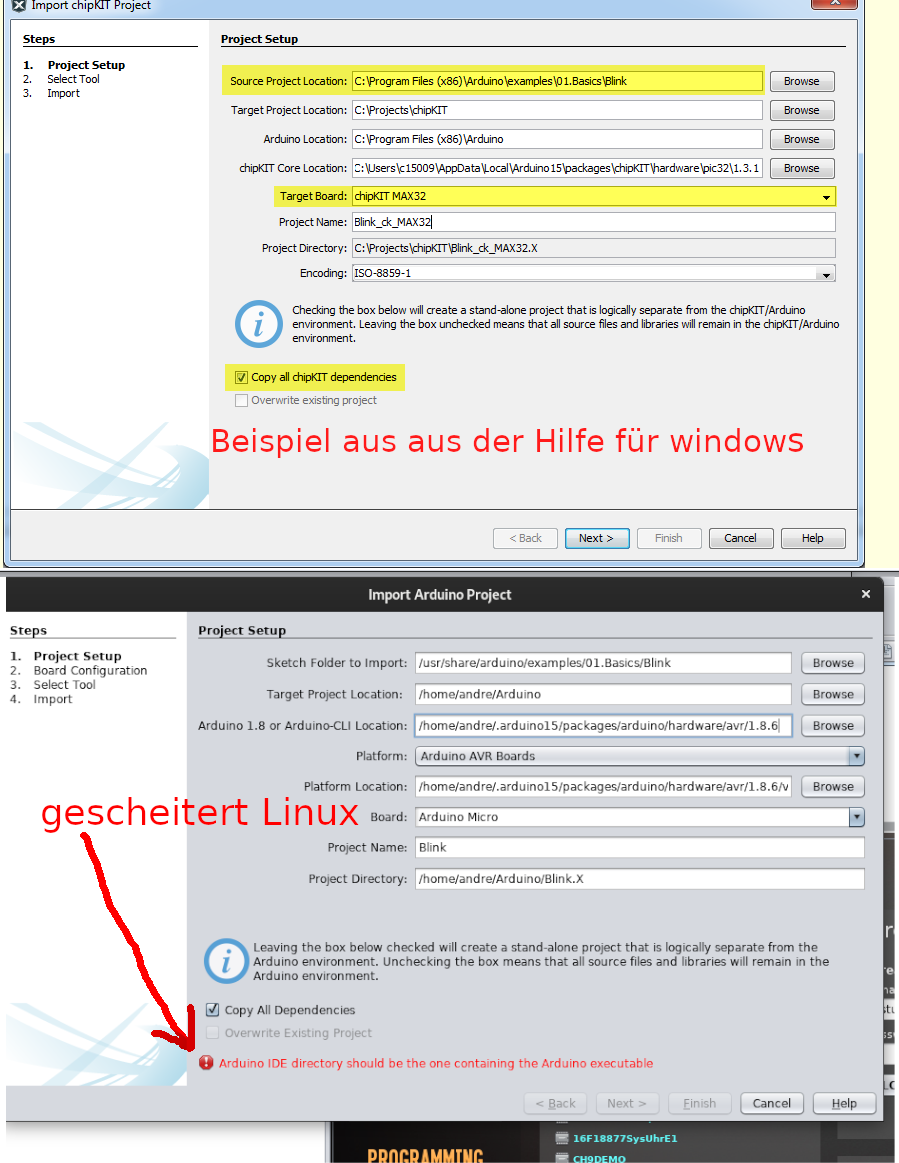
Vergleich von Projekt-Setup-Dialogen unter Windows und Linux
Project Setup Steps 1. Project Setup 2. Select Tool 3. Import Source Project Location: C:\Program Files (x86)\Arduino\examples\01.Basics\Blink Target Project Location: C:\Projects\chipKIT Arduino Location: C:\Program Files (x86)\Arduino chipKIT Core: C:\Users\15009\AppData\Local\Arduino15\packages\chipKIT\hardware\pic32\1.3.1 Target Board: chipKIT MAX32 Project Name: Blink_ck_MAX32 Project Directory: C:\Projects\chipKIT\Blink_ck_MAX32.X Encoding: ISO-8859-1 Checking the box below will create a stand-alone project that is logically separate from the chipKIT/Arduino environment. Leaving the box unchecked
in „gibts hier Leute die Mplap mit Linux Debian nutzen und sich schon länger mit uC beschäftigen?“ · Mikrocontroller und Digitale Elektronik · · Screenshots