-
Datei
lcd.h
display */ #define LCD_LINES 2 /**< number of visible lines of the display */ #define LCD_DISP_LENGTH 16 /**< visibles characters per line of the display */ #define LCD_LINE_LENGTH 0x0F /**< internal line length of the display */ #define LCD_START_LINE1 0x00 /**< DDRAM address of first char of line 1 */
in „LCD Problem“ · Mikrocontroller und Digitale Elektronik ·
-
Datei
lcd.h
display */ #define LCD_LINES 4 /**< number of visible lines of the display */ #define LCD_DISP_LENGTH 16 /**< visibles characters per line of the display */ #define LCD_LINE_LENGTH 0x40 /**< internal line length of the display */ #define LCD_START_LINE1 0x00 /**< DDRAM address of first char of line 1 */
in „LCD Atmega8535 fehler beim Programm erstellen mit AVR-Studio“ · Mikrocontroller und Digitale Elektronik ·
-
Datei
TEST.ASM
"m128def.inc" .nolist ; include-file nicht in Listing .include "m128def.inc" ; Definitionen für ATmega 128 einbinden .list ; Listing erstellen .def akku = r16 ; r16 als Rechenregister "akku" definieren .def msTimer = r23 ; r23 als Zeit-Einstellungsregister ; r24 als Zählregister .def templ = r17 ; Zwischenspeicher
in „16Bit Timer Problem (läuft nicht) | ATmega128“ · Mikrocontroller und Digitale Elektronik ·
-
PDF
RTC_AVR.pdf
Year 2000 Compliant Date Format Can be Used on all AVR Controllers with RTC Module “C”-Code for ATMega103 Inculded Note Introduction This application note describes how to implement a Real Time Clock (RTC) on AVR microcontrollers that features the RTC module. The implementation requires only one discrete
in „Läuft der Timer während seinem Interrupt weiter?“ · Mikrocontroller und Digitale Elektronik ·
-
Datei
uart.h
1200, 2400, 9600 */ #define UART_BAUD_SELECT(baudRate,xtalCpu) (((xtalCpu) + 8UL * (baudRate)) / (16UL * (baudRate)) -1UL) /** @brief UART Baudrate Expression for ATmega double speed mode * @param xtalCpu system clock in Mhz, e.g. 4000000UL for 4Mhz * @param baudRate baudrate in bps, e.g. 1200, 2400
in „Timerberechnung die hunderste“ · Mikrocontroller und Digitale Elektronik ·
-
Datei
uart.h
1200, 2400, 9600 */ #define UART_BAUD_SELECT(baudRate,xtalCpu) (((xtalCpu) + 8UL * (baudRate)) / (16UL * (baudRate)) -1UL) /** @brief UART Baudrate Expression for ATmega double speed mode * @param xtalCpu system clock in Mhz, e.g. 4000000UL for 4Mhz * @param baudRate baudrate in bps, e.g. 1200, 2400
in „Wie macht man solche Lichtmodes? Lauflicht, PWM und Co“ · Mikrocontroller und Digitale Elektronik ·
-
Datei
uart.h
1200, 2400, 9600 */ #define UART_BAUD_SELECT(baudRate,xtalCpu) (((xtalCpu) + 8UL * (baudRate)) / (16UL * (baudRate)) -1UL) /** @brief UART Baudrate Expression for ATmega double speed mode * @param xtalCpu system clock in Mhz, e.g. 4000000UL for 4Mhz * @param baudRate baudrate in bps, e.g. 1200, 2400
in „ATmega328p fehlerhafte UART-Anzeige mit bootloader“ · Mikrocontroller und Digitale Elektronik ·
-
Datei
test8mal7.asm
;testprogramm für atmega32 ;Plattform JY-MCU-board, betrieben über ISP ;fuses C0AF (ext. Crystal 16 MHz brown out 4V geht nicht, wg. Versorgung aus USB)) ;Betrieb der 8stelligen Binäranzeige über D7 (latch-übernahme),D6 data
in „ATMega32 16PU Typenunterschied?“ · Mikrocontroller und Digitale Elektronik ·
-
Datei
Timer.h
* Timer.h * * Created on: 10.08.2012 * Author: alex * * Dieser Quelcode ist optimiert für einen AtMega 16 * mit 16.000 kH Quarz */ #ifndef TIMER_H_ #define TIMER_H_ // Einbinden der Headerdateien #include <avr/io.h> #include <avr/interrupt.h> uint16_t T1_ms; uint16_t T1_s ; uint16_t T1_m ; uint16_t T2_ms ; uint16_t T2_s ; uint16_t T2_m ; uint16_t T3_ms ; uint16_t T3_s ; uint16_t T3_m ; uint16_t T4_ms ; uint16_t T4_s ; uint16_t T4_m ; /*..........................................................................
in „Universele Timer Headerdatei“ · Mikrocontroller und Digitale Elektronik ·
-
Datei
binaerzaehler_entprellt.asm
------------------------------------------------------------- .include "8535def.inc" ; Prozessor ATmega8 einbinden .def vara = r16 ; Register hochzaehlen .def varb = r17 ; LOOP1 .def varc = r18 ; LOOP2 .cseg ; Start eines Code Segments rjmp RESET RESET: ldi vara, 0x00 ; Register 16 als 0 laden out PORTA, vara ; Port-Register A setzen ldi vara, 0xFF ; Register 16 als 255 laden out DDRA, vara ; DDRA setzen (PIN 0 bis 7 Ausgaenge) ldi vara, 0x00 ; Register 16 als 0 laden out PORTB, vara ; Port-Register B setzen ldi vara, 0x00 ; Register 16 als 0 laden out DDRB,
in „Binaer zaehlen“ · Mikrocontroller und Digitale Elektronik ·
-
 Bild
Bild
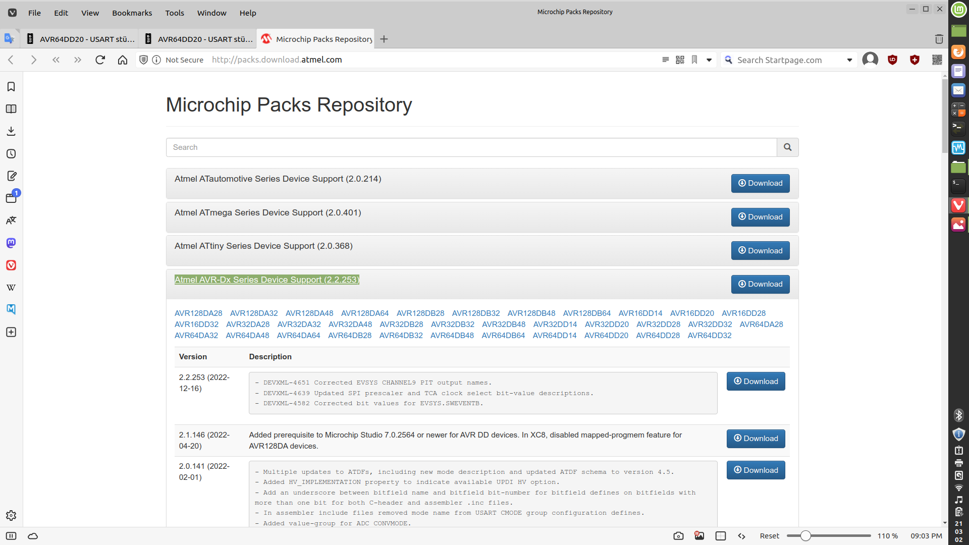
Microchip Packs Repository Webseite
Microchip Packs Repository Atmel Automotive Series Device Support (2.0.214) Download Atmel ATmega Series Device Support (2.0.401) Download Atmel ATtiny Series Device Support (2.0.368) Download Atmel AVR-Dx Series Device Support (2.2.253) Download AVR128DA48 AVR128DA32 AVR128DA48 AVR128DA64 AVR128DB28 AVR128DB32 AVR128DB48 AVR128DB64 AVR16DD14 AVR16DD20 AVR16DD28 AVR16DD32 AVR16DA32 AVR16DA48 AVR32DB28 AVR32DB32 AVR32DB48 AVR32DD14 AVR32DD20 AVR32DD28 AVR32DD32 AVR64DA28 AVR64DA32 AVR64DA48 AVR64DA64 AVR64DB28 AVR64DB32 AVR64DB48 AVR64DB64
in „AVR64DD20 - USART stürzt bei großem Buffer ab“ · Mikrocontroller und Digitale Elektronik · · Screenshots
-
Datei
Lauflicht.asm
: LDI r16, $3F ; Wert $3F an OUT PORTD, r16 ; PORTD ausgeben RETI led76: LDI r16, $9F ; Wert $9F an OUT PORTD, r16 ; PORTD ausgeben RETI led65: LDI r16, $CF ; Wert $CF an OUT PORTD, r16 ; PORTD ausgeben RETI led54: LDI r16, $E7 ; Wert $E7 an OUT PORTD, r16 ; PORTD ausgeben RETI led43: LDI r16, $F3 ; Wert $F3 an OUT PORTD, r16 ; PORTD ausgeben RETI led32: LDI r16, $F9 ; Wert $F9 an OUT PORTD, r16 ; PORTD ausgeben RETI led21
-
PDF
wama-online-dokumentation-public.pdf
3,90 3,90 1ATMEGA 32-16 DIP ATmega32 DIL http://www.reichelt.de/?ARTICLE=45026 0,10 0,10 1GS 40 IC-Sockel 40-pol http://www.reichelt.de/?ARTICLE=8224 C6 0,04 0,04 1RAD 105 100/35 Elko 100uF http://www.reichelt.de/?ARTICLE
-
Datei
Fernbedienung_mit_IRSND_mega8.c
/* * Fernbedienung_mit_IRSND_mega8.c * * Created: 30.07.2020 20:16:19 * Author: Andreas */ #define F_CPU 8000000L #include "irsnd.h" void timer1_init (void) { #if defined (__AVR_ATtiny45__) || defined (__AVR_ATtiny85__) // ATtiny45 / ATtiny85: OCR1C = (F_CPU / F_INTERRUPTS
in „IR Fernbedienung mit IRSND“ · Mikrocontroller und Digitale Elektronik ·
-
Datei
Fernbedienung_mit_IRSND_mega8.c
/* * Fernbedienung_mit_IRSND_mega8.c * * Created: 30.07.2020 20:16:19 * Author: Andreas */ #define F_CPU 8000000L #include "irsnd.h" void timer1_init (void) { #if defined (__AVR_ATtiny45__) || defined (__AVR_ATtiny85__) // ATtiny45 / ATtiny85: OCR1C = (F_CPU / F_INTERRUPTS
in „IR Fernbedienung mit IRSND“ · Mikrocontroller und Digitale Elektronik ·
-
Datei
lcd_gfx.c
Wenn nicht, siehe <http://www.gnu.org/licenses/>. * * lcd.h * * Created by Michael Köhler on 22.12.16. * Copyright 2016 Skie-Systems. All rights reserved. * * lib for OLED-Display with ssd1306/sh1106-Controller * first dev-version only for I2C-Connection * at ATMega328P like Arduino Uno *************
in „RS485 von ms - immer noch Einschaltprobleme“ · Mikrocontroller und Digitale Elektronik ·
-
Datei
source.txt
################################################################### # Makefile for the project mega16 ############################################################################### ## General Flags PROJECT = mega16 MCU = atmega16 TARGET = mega16.elf CC = avr-gcc.exe ## Options common to compile, link
in „AVR-AVR USART Verbindung“ · Mikrocontroller und Digitale Elektronik ·
-
Datei
lcd.h
display */ #define LCD_LINES 2 /**< number of visible lines of the display */ #define LCD_DISP_LENGTH 16 /**< visibles characters per line of the display */ #define LCD_LINE_LENGTH 0x40 /**< internal line length of the display */ #define LCD_START_LINE1 0x00 /**< DDRAM address of first char of line 1 */
in „Display geht immernoch nicht.“ · Mikrocontroller und Digitale Elektronik ·
-
Datei
16Kanal_Tongenerator.c
/* 16 Kanal Tongenerator mit programmierbaren Tonfolgen, Frequenzen und Geschwindigkeiten ATmega32 @ 8 MHz RC-Oszillator */ #include <avr/io.h> #include <avr/interrupt.h> // Pulsdaten, 500ms Raster, Kanal
in „Wie könnte man mit einem ATMEGA einen 8-fachen Rechteckgenerator erstellen?“ · Mikrocontroller und Digitale Elektronik ·
-
Datei
ad_mit_atm8.asm
pb0 als ausgabe ; ddrb = 1 sbi ddrb,pb0 ; adc configurieren ; left adjust, ; adc 3 pin 26(pc3) ldi r16,(1<<mux1)|(1<<mux0)|(1<<adlar) out admux,r16 loop: ldi r16,(1<<aden)|(1<<adsc)|(1<<adps2)|(1<<adps1)|(1<<adps0) out adcsra,r16 ;adsc wird nicht gesetzt im simulator ???? warte: sbic adcsra,adsc ; warte bis adc fertig rjmp warte ; skip if bit in i/o is cleard in r16,adch ; lese ergebnis rcall auswertung nop rjmp loop auswertung: cpi r16,128 brsh portb0_on rcall portb0_off ret portb0_off: cbi portb, pb0 ret portb0_on: sbi portb,pb0 ret
in „ad_wandler an atmega 8“ · Mikrocontroller und Digitale Elektronik ·
-
Datei
0001-spice-up-for-customized-edition.patch
/Makefile.inc @@ -6,7 +6,7 @@ # License: GNU GPL v2 (see License.txt) F_CPU = 16000000 -DEVICE = atmega8 +DEVICE = atmega32 # where the updating firmware should be located (starting address) FLASHADDRESS = 0x0000 @@ -16,14 +16,15 @@ FLASHADDRESS = 0x0000 DEFINES += -DCONFIG_NO__CHIP_ERASE -DCONFIG_NO
in „ATMEGA32 Minimum System Board“ · Mikrocontroller und Digitale Elektronik ·
-
PDF
IQP_500_GSM.pdf
Bereitstellung der Anschlüsse, die für die Bildaufnahme mit der IQP 500 benötigt werden. Der darauf verbaute Atmega8 übernimmt die informationstechnische Verarbeitung der Bilddaten. Das bedeutet, dass der Atmega8 die Kamera über seine serielle Schnittstelle (RXD und TXD) anspricht. Da die IQP 500 über die Möglichkeit
in „IQP 500 GSM Bildübertragung Tonerätzverfahren“ · Projekte & Code ·
-
Datei
TIMER_GNU.s
r16,0b00001000 ; Modus: Zählen bis Vergleichswert (WGM12=1) out TCCR1B,r16 ; Teiler+Modus schreiben ldi r16,lo8(18064) ; Vergleichswert speichern ldi r17,hi8(18064) out OCR1AH,r17 out OCR1AL,r16 in r16,TIMSK
in „Ölverbrauch Heizung anzeigen“ · Mikrocontroller und Digitale Elektronik ·
-
Datei
M8_Test_1.c
/*ATmega8 Lauflicht auf PORTD (PORTB von ATmega8 hat nur 6 I/O Pins auf STK500 !) Frequenz über Poti an PC0 regelbar Programme über Taster an PB0 durchschaltbar Taster mit Routine von P. Dannegger entprellt
in „mega8 Tastenentprellung“ · Mikrocontroller und Digitale Elektronik ·
-
Datei
debug_okay.asm
level changes uint16_t last_time = 0; // time of previous signal edge (in microseconds) uint16_t current_time = 0; // time of current signal edge (in microseconds) uint16_t duration = 0; // time between the last two signal
in „Fehler bei einfacher Integer-Division?“ · Mikrocontroller und Digitale Elektronik ·
-
Datei
main.c
by AVR Studio to detect if part is in Run or Stopped mode. uint8_t KP_PSB0; // H/L Used to set up a 16-bit addres in a Compare Register. PC will break on this addres. uint8_t KP_PSB1; // H/L Used to set up a 16-bit addres in a Compare Register. /********************************************************
in „AVR JTAG Programmierung“ · Mikrocontroller und Digitale Elektronik ·
-
PDF
Tremba_Magnetsteuerung.pdf
Magnetsteuerung MST-1630.001/002 Beschreibung Frei programmierbare Magnetsteuerung mit integriertem Atmelfi ATmega8 Mikroprozessor für Gleichstrommagnete bis 400 W oder Elektromotoren bis 200 W. Auf Hochleistung getrimmtes Layout für logische Schaltvorgänge im Industriebereich bis hin zur komplexen PWM-Taktung.
in „Analosignal mit Microkontroller auslesen“ · Mikrocontroller und Digitale Elektronik ·
-
PDF
Tremba_Magnetsteuerung.pdf
Magnetsteuerung MST-1630.001/002 Beschreibung Frei programmierbare Magnetsteuerung mit integriertem Atmelfi ATmega8 Mikroprozessor für Gleichstrommagnete bis 400 W oder Elektromotoren bis 200 W. Auf Hochleistung getrimmtes Layout für logische Schaltvorgänge im Industriebereich bis hin zur komplexen PWM-Taktung.
in „Spannungsregelung mit MC MST 1630 von Tremba“ · Mikrocontroller und Digitale Elektronik ·
-
PDF
Tremba_Magnetsteuerung.pdf
Magnetsteuerung MST-1630.001/002 Beschreibung Frei programmierbare Magnetsteuerung mit integriertem Atmelfi ATmega8 Mikroprozessor für Gleichstrommagnete bis 400 W oder Elektromotoren bis 200 W. Auf Hochleistung getrimmtes Layout für logische Schaltvorgänge im Industriebereich bis hin zur komplexen PWM-Taktung.
in „Spannungsregelung mit MC MST 1630 von Tremba (2)“ · Mikrocontroller und Digitale Elektronik ·
-
Datei
SLEEP.ASM
ldi r16, 0xff out portd, r16 ;pull ups out ddrb, r16 ;debug LEDs ldi tmp, LOW(RAMEND) out SPL, tmp ldi tmp, HIGH(RAMEND) out SPH, tmp ldi tmp, (1<<TOIE0) | (1<<OCIE1A) out TIMSK, tmp ldi tmp, $2 out OCR1AH,
in „Die PowerDown-Tücke!“ · Mikrocontroller und Digitale Elektronik ·
-
Datei
RADIOCONTEST.asm
.NOLIST .INCLUDE "m328Pdef.inc" ; Befehlsliste des ATMega328P .LIST .def temp1 = r16 .def temp2 = r19 .def segm0 = r20 .def segm1 = r21 .def segm2 = r22 .def tempadc = r23 .equ SCHIEBE_DDR = DDRD .equ SCHIEBE_PORT = PORTD .equ SCK = 0 .equ SIN = 1 .equ RCK
in „Zeigt her eure Kunstwerke (2017-2019)“ · Projekte & Code ·
-
Datei
config.xml
BOOTSZ0="0"/> <Setting caption="128 words" BOOTSZ1="1" BOOTSZ0="1"/> </BootSize> </AVR> <AVR name="m16" caption="ATmega16"> <Fuse name="OCDEN" bit="7" fuseByte="hfuse" default="1" desc="Enable OCD (on chip debug)" mode="expert"/> <Fuse name="JTAGEN" bit="6" fuseByte="hfuse" default="0" desc="Enable JTAG
in „Fuseeditor, grafische Benutzeroberfläche für AVRdude“ · Projekte & Code ·
-
Datei
Lauflicht.asm
TIMSK, r16 ; Timer0 aktivieren LDI r16, $F0 ; Timer-Zählregister OUT TCNT0, R16 ; auf F0 voreingestellt LDI r16, $05 ; Takt-Vorteiler OUT TCCR0, r16 ; auf 1024 stellen LDI zaehler, $00 ; Zählregister initialisieren
-
Datei
Programm.txt
//////////////////////////////////////////////////////////////////////////////////// Chip type : ATmega8 Program type : Application Clock frequency : 10,000000 MHz Memory model : Small External SRAM size : 0 Data Stack size : 256 *********************************************/ #include <mega8.h> #include
in „ATMEGA8 -- SD/MMC Karte“ · Mikrocontroller und Digitale Elektronik ·
-
Datei
TimerOne.cpp
/* * Interrupt and PWM utilities for 16 bit Timer1 on ATmega168/328 * Original code by Jesse Tane for http://labs.ideo.com August 2008 * Modified March 2009 by Jérôme Despatis and Jesse Tane for ATmega328 support * Modified June 2009 by Michael
in „Rotary Encoder macht immer 4 Schritte“ · Mikrocontroller und Digitale Elektronik ·
-
PDF
Lora_MainboardOutputJob.PDF
RX2- PX?05 PIC?1 DCD# PIC01 PIX?11 RX2+ PX?04 PIC?1 CTS# PIC01 PIX?12 PX?03 PIC?1 PIC01 GND CBUS4 16 USB-C/12401548E4#2A PIC?1 CBUS2 PIC01 PIC?1 CBUS3 PIC01 CIC? PII?0 PIC07 FT232RL GND 46 PII?0 UART_RTS PIC06 PR? PII?0 UART_CTS PIC05 PII?0 RESERVED PIC04 PII?0 PIC03 RESERVED 42 PI?1 PIR02 P10K PII?
in „Bootloader über Arduino auf Atmega328“ · Mikrocontroller und Digitale Elektronik ·
-
Datei
m8def.inc
" ;* Title : Register/Bit Definitions for the ATmega8 ;* Date : 2005-01-11 ;* Version : 2.14 ;* Support E-mail : avr@atmel.com ;* Target MCU : ATmega8 ;* ;* DESCRIPTION ;* When including this file in the assembly program file, all I/O register ;* names
in „Probleme mit rjmp beim AVR Atmega 8L“ · Mikrocontroller und Digitale Elektronik ·
-
Datei
m8def.inc
" ;* Title : Register/Bit Definitions for the ATmega8 ;* Date : 2011-02-09 ;* Version : 2.35 ;* Support E-mail : avr@atmel.com ;* Target MCU : ATmega8 ;* ;* DESCRIPTION ;* When including this file in the assembly program file, all I/O register ;* names
in „AVR8ASM TWI Interrupt“ · Mikrocontroller und Digitale Elektronik ·
-
Datei
m8def.inc
" ;* Title : Register/Bit Definitions for the ATmega8 ;* Date : 2011-02-09 ;* Version : 2.35 ;* Support E-mail : avr@atmel.com ;* Target MCU : ATmega8 ;* ;* DESCRIPTION ;* When including this file in the assembly program file, all I/O register ;* names
in „AVR8ASM TWI Interrupt“ · Mikrocontroller und Digitale Elektronik ·
-
Datei
m8def.inc
" ;* Title : Register/Bit Definitions for the ATmega8 ;* Date : 2011-02-09 ;* Version : 2.35 ;* Support E-mail : avr@atmel.com ;* Target MCU : ATmega8 ;* ;* DESCRIPTION ;* When including this file in the assembly program file, all I/O register ;* names
in „AVR8ASM TWI Interrupt“ · Mikrocontroller und Digitale Elektronik ·
-
Datei
m8def.inc
" ;* Title : Register/Bit Definitions for the ATmega8 ;* Date : 2011-02-09 ;* Version : 2.35 ;* Support E-mail : avr@atmel.com ;* Target MCU : ATmega8 ;* ;* DESCRIPTION ;* When including this file in the assembly program file, all I/O register ;* names
in „AVR8ASM TWI Interrupt“ · Mikrocontroller und Digitale Elektronik ·
-
Datei
m8def.inc
" ;* Title : Register/Bit Definitions for the ATmega8 ;* Date : 2011-02-09 ;* Version : 2.35 ;* Support E-mail : avr@atmel.com ;* Target MCU : ATmega8 ;* ;* DESCRIPTION ;* When including this file in the assembly program file, all I/O register ;* names
in „AVR8ASM TWI Interrupt“ · Mikrocontroller und Digitale Elektronik ·
-
Datei
m8def.inc
" ;* Title : Register/Bit Definitions for the ATmega8 ;* Date : 2011-08-25 ;* Version : 2.35 ;* Support E-mail : avr@atmel.com ;* Target MCU : ATmega8 ;* ;* DESCRIPTION ;* When including this file in the assembly program file, all I/O register ;* names
in „AVR-Mikrocontrollertechnik-Kursus in Assembler besprechung“ · Mikrocontroller und Digitale Elektronik ·
-
Datei
m8def.inc
" ;* Title : Register/Bit Definitions for the ATmega8 ;* Date : 2011-08-25 ;* Version : 2.35 ;* Support E-mail : avr@atmel.com ;* Target MCU : ATmega8 ;* ;* DESCRIPTION ;* When including this file in the assembly program file, all I/O register ;* names
in „AVR-Mikrocontrollertechnik-Kursus in Assembler besprechung“ · Mikrocontroller und Digitale Elektronik ·
-
Datei
main.c
#include <avr/io.h> #include <inttypes.h> // funktionen wie uint16_t erlaubenn #include <avr/interrupt.h> #define UBRR_VAL ((F_CPU+BAUD*8)/(BAUD*16)-1) // clever runden #define BAUD_REAL (F_CPU/(16*(UBRR_VAL+1))) // Reale Baudrate #define BAUD_ERROR ((BAUD_REAL*1000
in „ATMEGA32 (Daten verarbeiten und senden)“ · Softwareentwicklung ·
-
Datei
Example1_DisplayTest.ino
myTOLED.pixelSet(92, 15); myTOLED.pixelSet(93, 15); myTOLED.pixelSet(94, 15); myTOLED.pixelSet(76, 16); myTOLED.pixelSet(77, 16); myTOLED.pixelSet(78, 16); myTOLED.pixelSet(79, 16); myTOLED.pixelSet(80, 16); myTOLED.pixelSet(81, 16); myTOLED.pixelSet(82, 16); myTOLED.pixelSet(83, 16); myTOLED.pixelSet(84, 16); myTOLED.pixelSet(85, 16); myTOLED.pixelSet(86, 16); myTOLED.pixelSet(87, 16); myTOLED.pixelSet(88, 16); myTOLED.pixelSet(89, 16); myTOLED.pixelSet(90, 16); myTOLED.pixelSet(91, 16); myTOLED.pixelSet
in „Arduino OLED Display Ansteuern & "Hello World" Programme gehen nicht.“ · Softwareentwicklung ·
-
PDF
techb_myavr_board_20.pdf
Beschreibung myAVR myAVR Board 2.0 USB • Lern- und Experimentierboard für ATMEL Mikrocontroller (ATmega8/48/88/168) • Mit Controller und typischen Ein- und Ausgabegeräten (Taster, LEDs, usw.) • Material: FR4, 1,5 mm; 0.35 µm Cu • Leiterplatte gebohrt, verzinnt, Industriefertigung, robust, bedruckt •
in „Probleme mit rjmp beim AVR Atmega 8L“ · Mikrocontroller und Digitale Elektronik ·
-
Datei
avra_test_list.txt
sbrc" ;* (skip if bit in register set/cleared). The following example illustrates ;* this: ;* ;* in r16,PORTB ;read PORTB latch ;* sbr r16,(1<<PB6)+(1<<PB5) ;set PB6 and PB5 (use masks, not bit#) ;* out PORTB,r16 ;output to PORTB ;* ;* in r16,TIFR ;read the Timer Interrupt Flag Register ;* sbrc r16,TOV0
in „AVR mit Linux Programmieren“ · Mikrocontroller und Digitale Elektronik ·
-
Datei
rainbow.c
/* * * This example is configured for a Atmega32 at 16MHz */ //#include <util/delay.h> #include <avr/io.h> #include <avr/eeprom.h> #include <stdlib.h> #include <avr/interrupt.h> #include "light_ws2812.h" #include "irmpconfig.h" #include "irmp.h
in „Lightweight WS2811/WS2812 Library“ · Mikrocontroller und Digitale Elektronik ·
-
Datei
keymatrix.c
keys ^= KEY_PIN<<8; // key 5..9 = bit 10..14 KEY_DDR = 1<<KEY_COL0; // col0 = low return ~keys; } u16 key_state; // debounced key state: // bit = 1: key pressed u16 key_press; // key press detect ISR(TIMER0_OVF_vect ) { static u16 ct0, ct1; u16 i; TCNT0 = (u16)(256 - XTAL / 1024 / 100); // 100Hz (10ms
in „2x5 Tastenmatrix an AT90USB1287“ · Mikrocontroller und Digitale Elektronik ·