-
 Bild
Bild
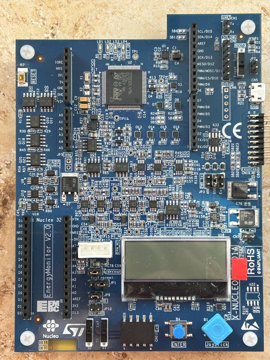
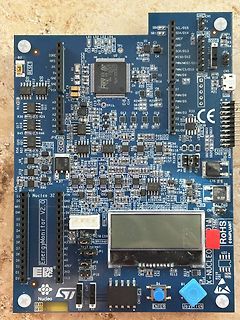
ST Nucleo-144 Entwicklungskit mit Display
LD1 LD2 LD3 LD4 SCL/D15 SDA/D14 STL NRK CN2 GND SCK/D13 MISO/D11 PWM/D5 CIN/D10 PWM/D6 PWM/D5 D7 D4 PWM/D3 RX/D2 TX/D1 PA15 bis PA0 USB CN5 R21 R26 R28 R32 R33 R34 R35 R36 R37 R38 R39 R40 R41 R42 R43 R44 R45 R46 R47 R48 R49 R50 R51 R52 R53 R54 R55 R56 R57
-
 Bild
Bild
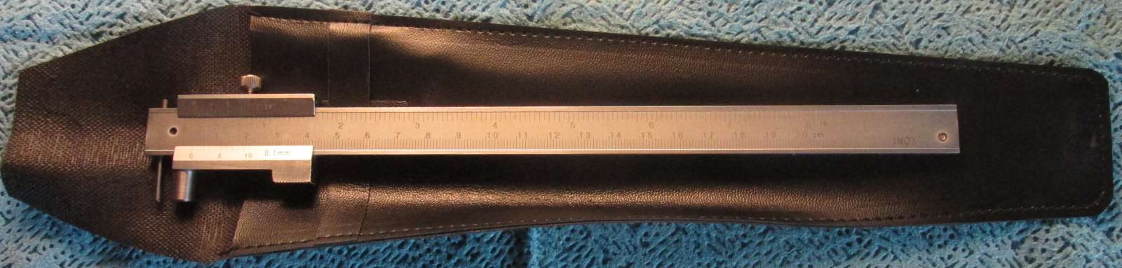
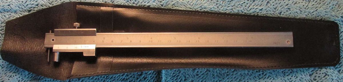
Schieblehre in einer Lederscheide
10 0.1mm 3 4 5 6 7 8 9 10 11 12 13 14 15 16 17 18 19 20 cm INOX
-
 Bild
Bild
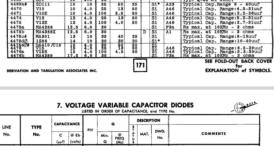
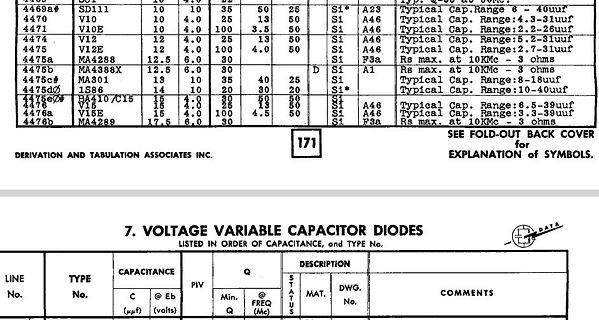
Tabelle mit Daten für spannungsvariable Kapazitätsdioden
CAPACITANCE, and TYPE No. 4469a# SD111 10 35 50 25 S1* A23 Typical Cap. Range 4.3-31uuf 4470 V10 10 4.0 25 13 S0 A46 Typical Cap. Range 4.3-31uuf 4471 V10E 10 4.0 100 3.5 S0 A46 Typical Cap. Range 2.2-26uuf 4474 V12 12 4.0 25 13 S0 A46 Typical Cap. Range 5.2-31uuf 4475 V12E 12 4.0 100 3.5 S0 A46 Typical Cap.
-
 Bild
Bild
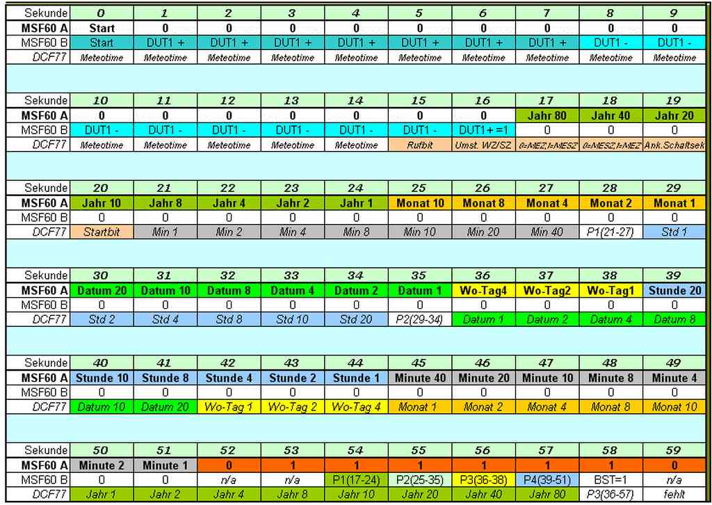
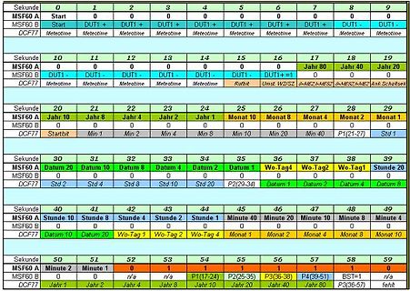
Tabelle mit Zeitverlauf von MSF60 A, MSF60 B und DCF77
0 0 MSF60 B Start DUT1+ DUT1+ DUT1+ DUT1- DUT1- DUT1- DCF77 Meteotime Meteotime Meteotime 10 11 12 13 14 15 16 17 18 19 MSF60 A 0 0 0 DUT1- 0 0 0 Jahr 80 Jahr 40 Jahr 20 MSF60 B 0 DUT1- 0 DUT1- 0 DUT1- 0 DUT1- 0 DUT1+ =1 0 0 DCF77 Meteotime Meteotime Meteotime Rufbit Umst. WZ/S2 MEZ MEZ MEZ Ank.Schaltsek
-
 Bild
Bild
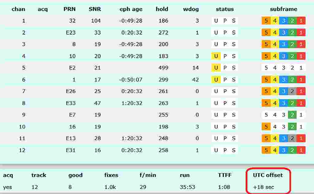
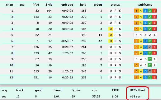
Tabelle mit GPS-Messdaten
E33 47 1:20:32 263 1 U P S 5 4 3 2 1 9 E7 19 255 U P S 5 4 3 2 1 10 16 19 198 3 U P S 5 4 3 2 1 11 E13 28 1:20:32 248 0 U P S 5 4 3 2 1 12 E31 16 0:20:32 258 1 U P S 5 4 3 2 1 acq track good fixes f/min run TTFF UTC offset yes 12 8 1.0k 29 35:53 1:08 +18 sec
-
 Bild
Bild
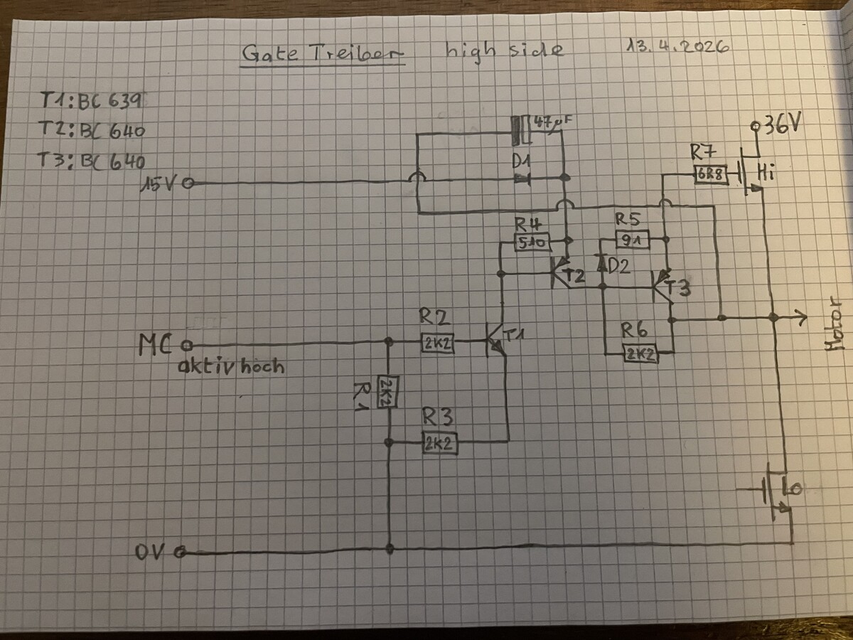
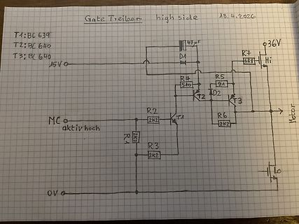
Handgezeichneter Schaltplan eines Gate-Treibers
Gate Treiber high side 13.4.2026 T1:BC639 T2:BC640 T3:BC640 15V 47uF 36V R7 688 Hi R4 510 R5 91 D1 D2 T2 T3 MC o aktiv hoch R2 2k2 R6 2k2 T1 R1 2k2 R3 2k2 Motor 0V
-
Thread
Softwareupdates durch die Bank: CubeMX mit Vorschaufunktion, neues Quartus uvam
Neuinstallationen. Der Rest des Updates besteht dann vor allem aus Fehlerbehebungen: [c] 2026-04-13: * Passwordless sudo now disabled by default * Switch to enable passwordless sudo added to Control Centre System tab and to raspi-config * New Main Menu tab added to Control Centre to allow
Beitrags herangezogen haben. Wie immer gilt, dass unter der URL https://www.cnx-software.com/2026/04/13/linux-7-0-release-main-changes-arm-risc-v-and-mips-architectures/ eine für den Embedded-Bereich vorgesehene Auflistung der Neuerungen zu finden ist. Allgemeine Veränderungen, beispielsweise für den Workstation
-
 Bild
Bild
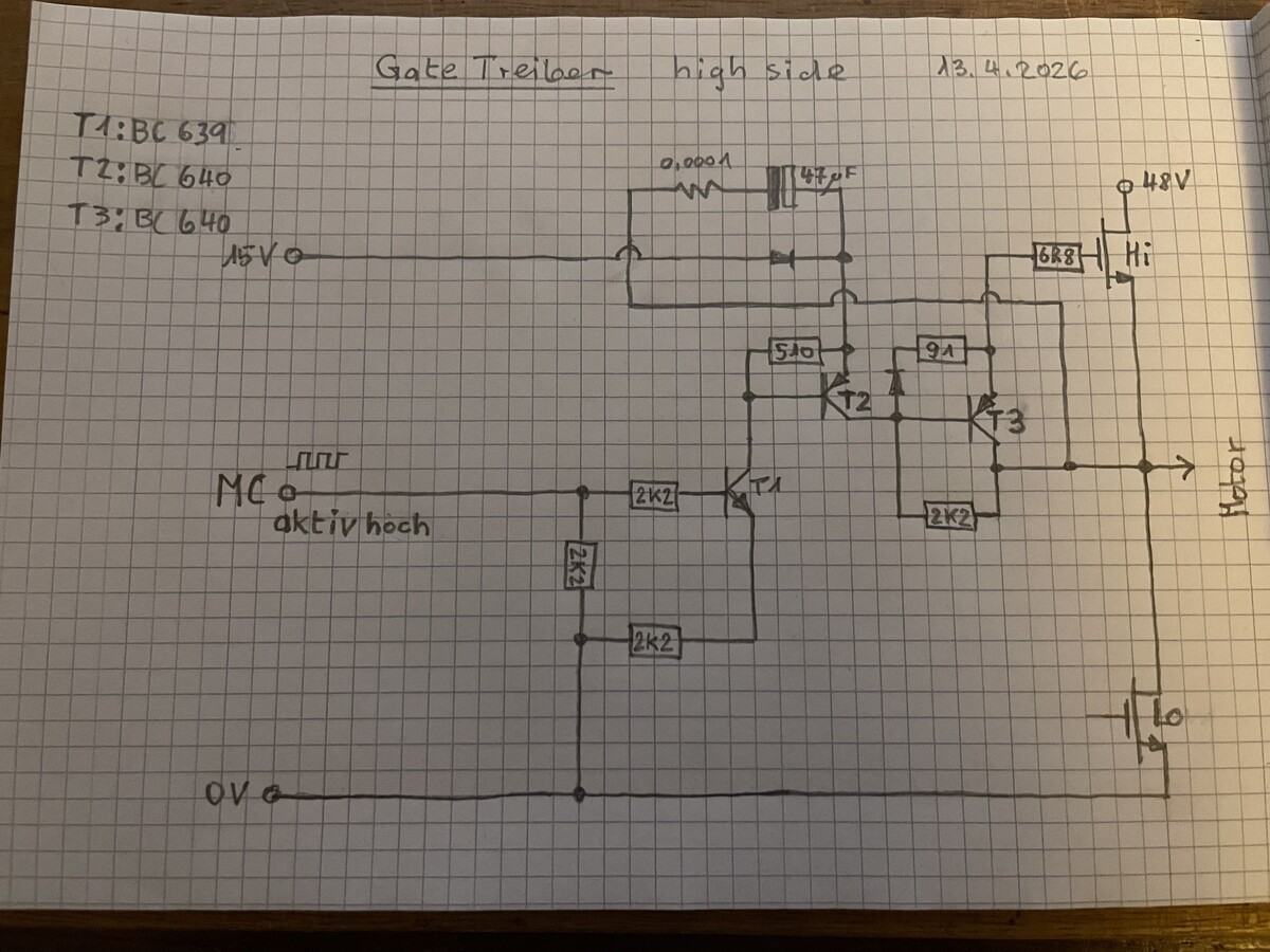
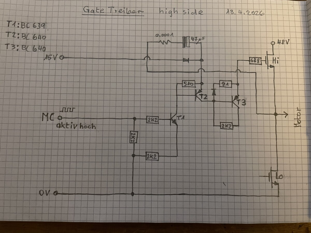
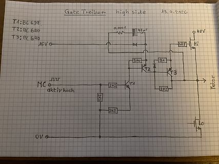
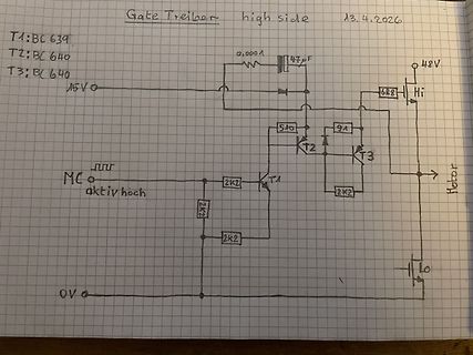
Handgezeichneter Schaltplan einer Gate-Treiber-Schaltung
Gate Treiber high side 13.4.2026 T1:BC 639 T2:BC 640 T3:BC 640 15V 0,0001 47uF 48V 68R Hi 510 91 T2 T3 MC aktiv hoch 2K2 T1 2K2 2K2 Motor 0V
-
 Bild
Bild
Handgezeichneter Schaltplan eines Gate-Treibers
Gate Treiber high side 13.4.2026 T1:BC 639 T2:BC 640 T3:BC 640 15V 0,0001 47uF 48V 68R Hi 510 91 MC aktiv hoch 2K2 T1 2K2 2K2 Motor 0V
-
Thread
WLAN Abbrüche durch NVR?
kann hier noch helfen? Die Telekom? Ein Kanalwechsel. Auf Überlappungen achten (1/6/11 oder 1/5/9/13).
-
 Bild
Bild
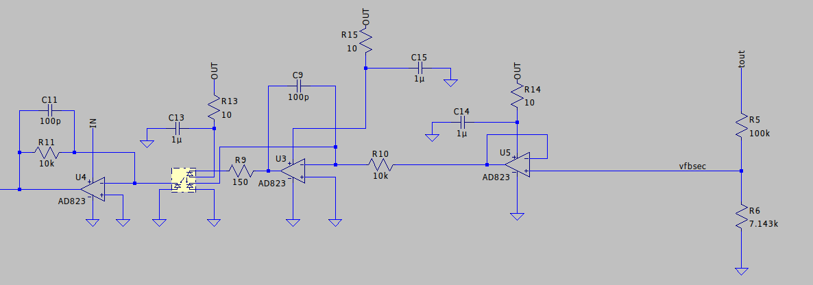
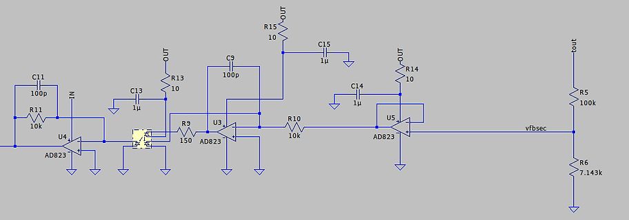
Schaltplan mit Operationsverstärkern AD823
C11 100p R11 10k U4 AD823 IN OUT C13 1µ R9 150 U3 AD823 C9 100p R13 10 OUT R15 10 C15 1µ R10 10k U5 AD823 C14 1µ R14 10 OUT vfbsec R5 100k R6 7.143k
-
Thread
Welche Tastköpfe kaufen?
Probiere es mal damit: https://www.pollin.de/p/uni-t-oszilloskop-tastkopf-ut-p04-10-1-100-mhz-831089 13 Euronen https://www.pollin.de/p/uni-t-oszilloskop-tastkopf-ut-p05-10-1-200-mhz-831090 16 Euronen
-
 Bild
Bild
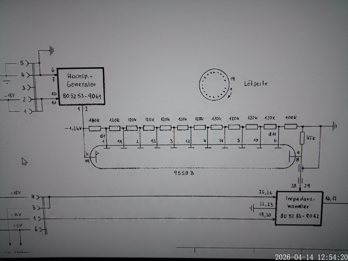
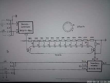
Schaltplan eines Hochspannungsgenerators
4 3 2 1 -15V 6 7 10 Hochsp.-Generator 80 52 53-9061 1 2 180k 120k 120k 120k 100k -1,2kV d1 1 14 2 13 3 12 4 11 5 10 d1 6 47k 9 8 19 14 9558 V 28 29 25,26 Impedanz-wandler 16,7 80 52 53-9062 22,23 19,20 +15V 4 3 -15V 1 +15V 6 Lötseite 19
-
 Bild
Bild
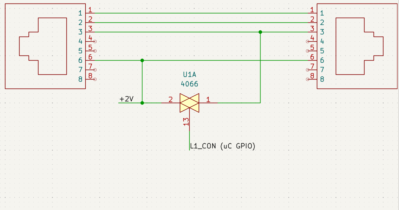
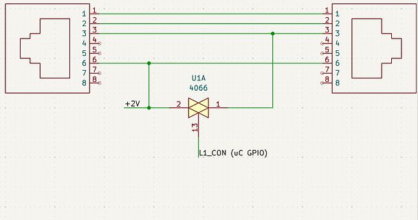
Schaltplan eines IC-Anschlusses
1 2 3 4 5 6 7 8 1 2 3 4 5 6 7 8 U1A 4066 2 1 +2V 13 L1_CON (uC GPIO)
-
Thread
Radiokompass umbau auf Netzbetrieb
: Lagerliste_17, ohne Datum Lagerliste_15, ohne Datum Lagerliste_14, ohne Datum Lagerliste_13, ohne Datum Lagerliste_12, (1983) Lagerliste_11, ohne Datum Lagerliste_10, ohne Datum Willi Ebel 4760 Werl-Mawicke Surplus-Katalog 05, 1985 Surplus-Katalog 01, 1981 Büscher Flugversand 3549
vorhanden. Es gibt sogar eine Dienstvorschrift für damals erbeutete Geräte. Die nennt sich D50/13 Kennblätter fremden Geräts. Darin konnte ich das Gerät leider nicht finden. Auf jeden Fall könnte ich mir vorstellen das man das genutzt hat um Versuche anzustellen, wie man das Signal beeinflussen
-
 Bild
Bild
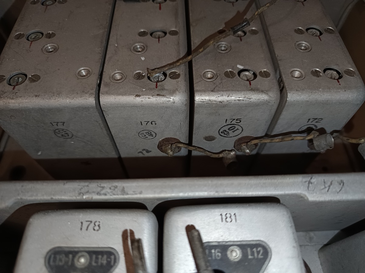
Metallgehäuse von elektronischen Bauteilen mit Nummern
177 176 175 172 178 181 L13-1 L14-1 L16 L12
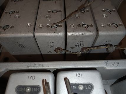
-
 Bild
Bild
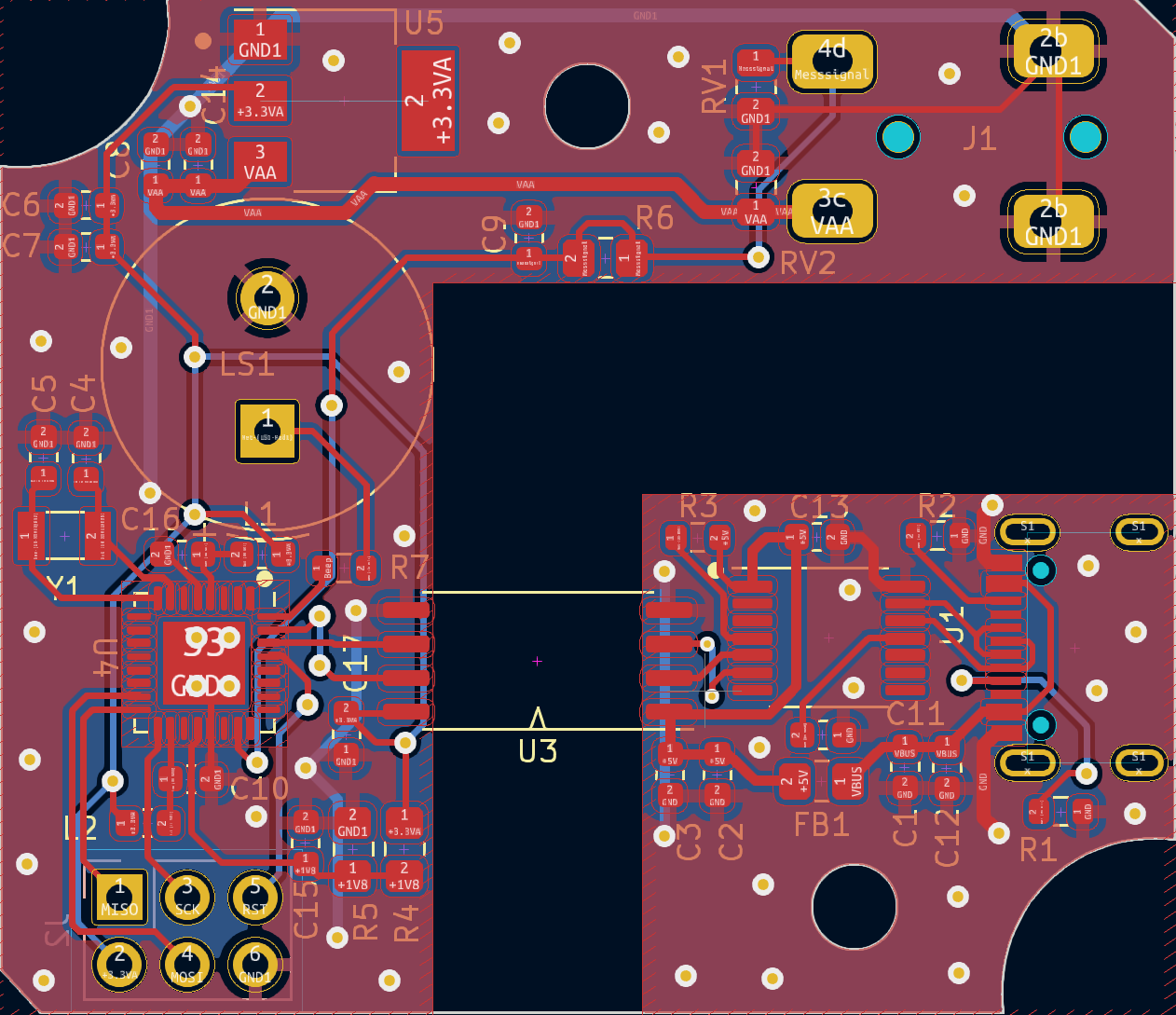
CAD-Ansicht eines Leiterplatten-Layouts
1 GND 2 GND C15 1 +1VB R5 2 R4 1 +1VB C3 2 GND C2 1 GND FB1 C1 1 VBUS C12 2 GND R2 1 VDD R3 2 VDD C13 2 VDD U1 1 VBUS 2 GND
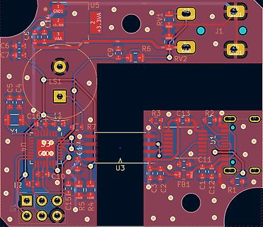
-
 Bild
Bild
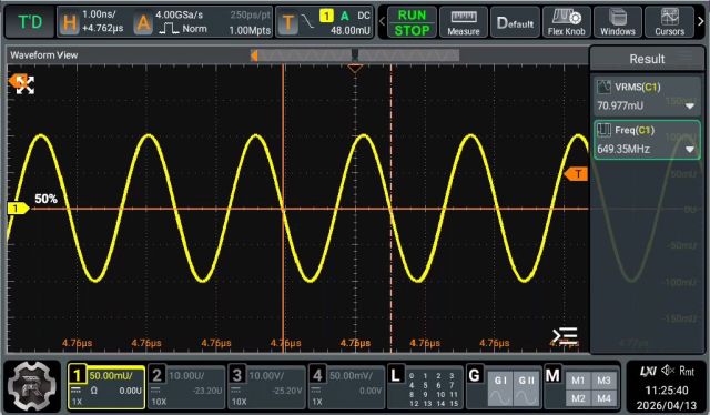
Oszilloskop-Screenshot einer Sinuswelle
0.00U 2 10.00U/ -23.20U 3 10.00V/ 10X 4 50.00m/V/ 10X -25.20U 0.00V L 0 1 2 3 4 5 6 7 8 9 10 11 12 13 14 15 G GI GII M M1 M2 M3 11:25:40 2026/04/13
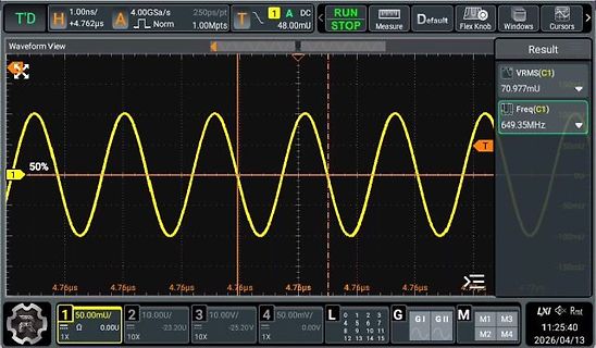
-
 Bild
Bild
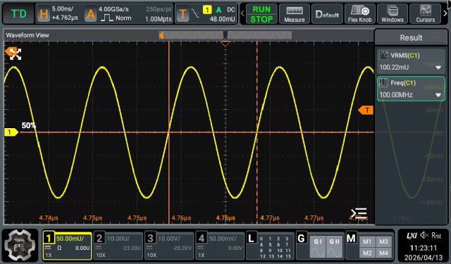
Oszilloskop-Screenshot einer Sinuswelle
4.77us 50.00m/Ω 0.00U 10.00U/ -23.20U 10.00V/ 100.00MHz 50.00mV/ 1X -25.20V 1X 0.00V 11:23:21 2026/04/13
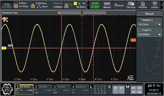
-
 Bild
Bild
Screenshot einer Oszilloskop-Softwareoberfläche
upgrade option 8 Limit 1 50.00mV/ 2 10.00/ 3 10.00V 4 50.00mV/ L 0 1 2 3 G GI G M M1 M2 11:51:03 2026/04/13
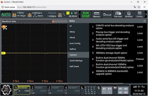
-
 Bild
Bild
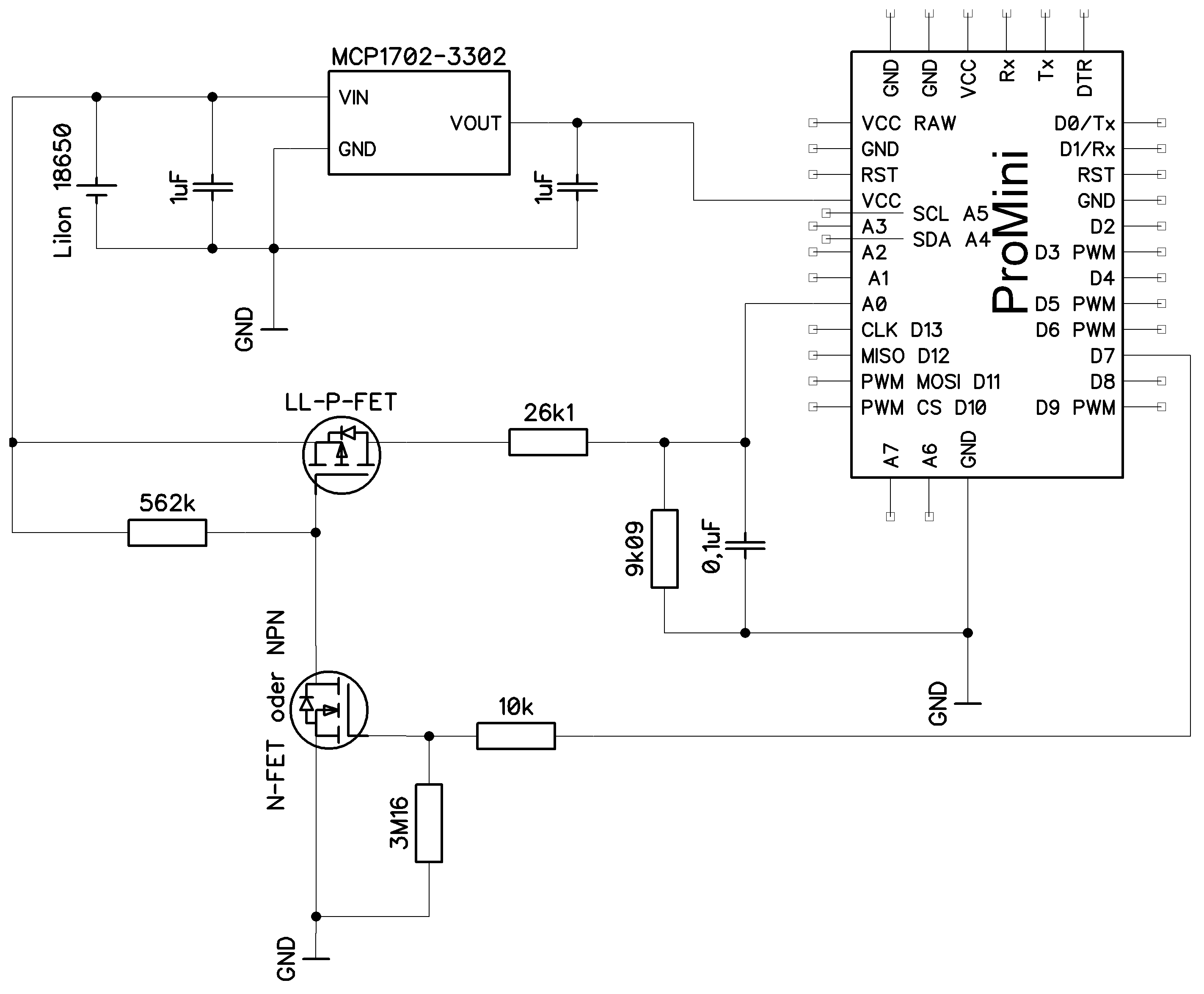
Schaltplan mit Pro Mini, MCP1702-3302 und MOSFETs
Rx, RST, GND, D2, D3 PWM, D4, D5 PWM, D6 PWM, D7, D8, D9 PWM, CS, D10, MOSI, D11, MISO, D12, CLK, D13, SDA, A4, A5, SCL, A3, A2, A1, VCC, A0, A7, A6, GND, LL-P-FET, 26k1, 562k, 9k09, 0,1uF, N-FET oder NPN, 10k, 3M16, GND
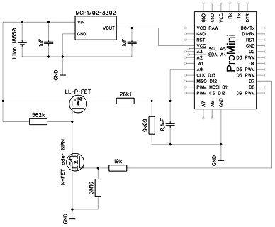
-
 Bild
Bild
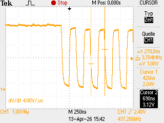
Oszilloskop-Messung eines Rechtecksignals
Cursor 1 420ns 2.04V Cursor 2 690ns 3.12V dV/dt 4.00V/µs CH1 1.00VBW M 250ns CH1 2.40V 437.286kHz 13-Apr-26 15:42
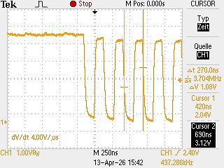
-
 Bild
Bild
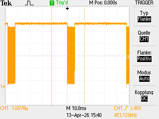
Oszilloskop-Screenshot eines Rechtecksignals
Flanke CH1 Quelle Flanke: Positiv Modus Auto Kopplung DC CH1 1.00VB M 10.0ms CH1 2.40V 451.133kHz 13-Apr-26 15:40
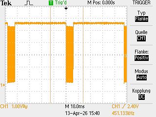
-
Thread
Turtlegrafik: Interpreter, Creator & Designer
heißt also: [code] static const char cmd[] PROGMEM = "P0,0 c15 T159,79 M15,67 c2 K7 r12 K7 r13 K7 r13 K7 M-45,-1 c15 T55,8 c6 M52,-1 T53,-1 c8 M4,-2" "T47,-27 C27,66,10M6,0 T11,-13 C205,207,56 u13 r11 M-6,7 c6 l3 d1 c15 M15,-11 T10,6 M14,0 T8,6" "C27,66,10 M-15,7T12,1 M14,0 T10,1 c1 M-13
TURTLE turtle(tft); static const char cmd[] PROGMEM = "P0,0 c15 T159,79 M15,67 c2 K7 r12 K7 r13 K7 r13 K7 M-45,-1 c15 T55,8 c6 M52,-1 T53,-1 c8 M4,-2" "T47,-27 C27,66,10M6,0 T11,-13 C205,207,56 u13 r11 M-6,7 c6 l3 d1 c15 M15,-11 T10,6 M14,0 T8,6" "C27,66,10 M-15,7T12,1 M14,0 T10,1 c1 M-13
-
Thread
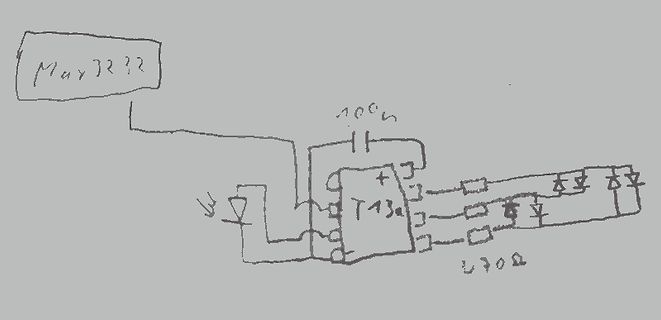
Attiny13a stürzt ab
kann als die alten AVRs mit ISP – und selbst bei Reichelt sind die nur halb so teuer wie ein ATtiny13A.
Stunden auf dem ATtiny13A nicht auf.
-
 Bild
Bild
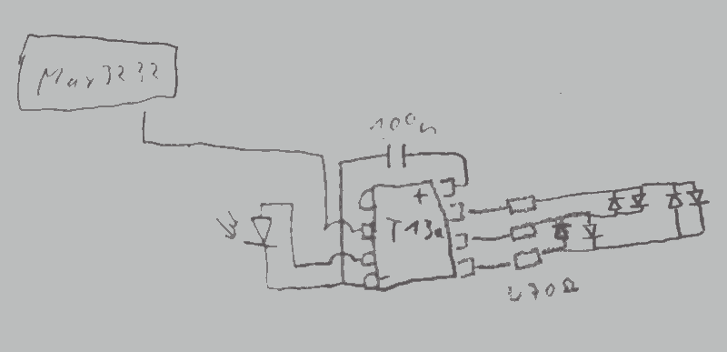
Handgezeichneter Schaltplan mit Bauteilen
May 32?? 100n T13 730Ω
-
Thread
DSO mit Funktionsgenerator statt Lüfter?
nur 8 MPts Speicher Leg mal eine /neue/ Platte auf. Die hat einen Sprung. Das wurde schon am 13.04.2026 um 11:35 festgestellt. Hantek hat immerhin wesentlich eher als Rigol, 7" Oszis auf den Markt gebracht. Da gab es bei Rigol noch 5" 320x240 Mäusekino im gleichen Preissegment. Vermutlich
-
Thread
Suche nach geeignetem OpAmp als Impedanzwandler
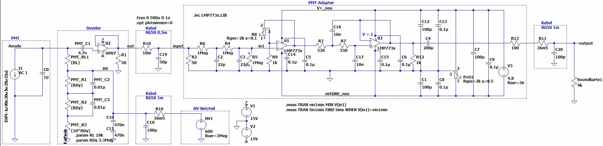
bei dne paar kHz die der OP07 abkann. Ebenso sollte der TE wenn es schon an Impedanz denkt den R13 auf sdiw 50 Ohm ändern. Was sich nie verstehen werde: Warum frickelt man einen solchen Verstärker selbst, wenn man all das vom PMT Hersteller aus dessen Sotiment sauber abgestimmt fertig kaufen (könnte
125419_1_.jpg > > 220 KB warum greifst du nicht den Vorschlag von Lothar vom 14.4. 13:12 auf und baust die Sache statt mit einen hochohmigen Impedanzwandler mit einen Transimpedanzverstärker auf. Also positiven Eingang direkt auf Masse und mit der PMT ohne Koppelkondensator direkt auf
-
 Bild
Bild
Schaltplan einer PMT-Adapter Schaltung
1Meg R4 1Meg C3 22p R5 22p R2 22p C5 0.1u U1 LMP773x in1 R9 714c C16 10n 330 R7 330 U3 LMP773x V=1 C13 0.1u C4 200u C12 100u C7 100u C9 0.1u R13 100 Kabel RG58 1m C20 100p output Soundkarte 4k V3 Rser=36 Pot1 1 Rges=2k a=0.5 C8 100u C1 100u virtGND_neu .meas TRAN vin1min MIN V(in1) .meas TRAN tin1min
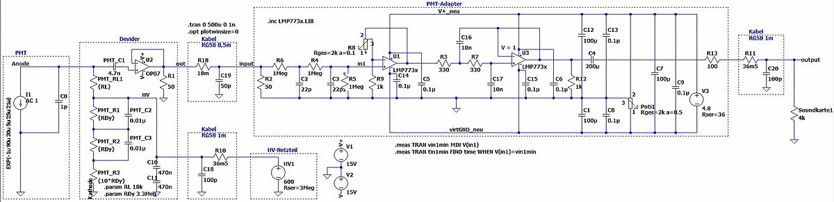
-
 Bild
Bild
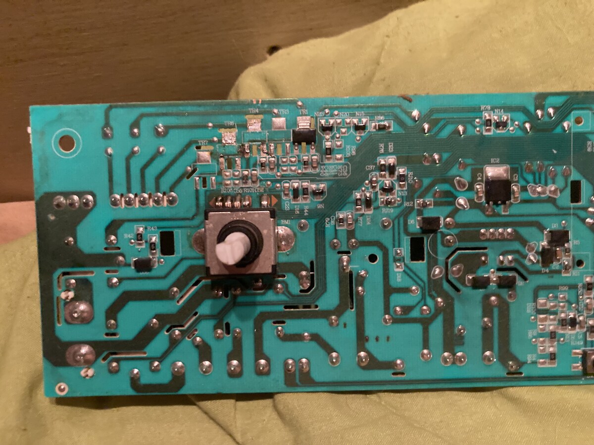
Foto einer grünen Leiterplatte mit Bauteilen
R38 R37 R36 R35 R34 R33 R32 R31 R30 R29 R28 R27 R26 R25 R24 R23 R22 R21 R20 R19 R18 R17 R16 R15 R14 R13 R12 R11 R10 R9 R8 R7 R6 R5 R4 R3 R2 R1
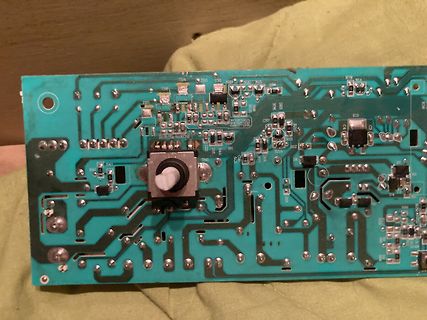
-
 Bild
Bild
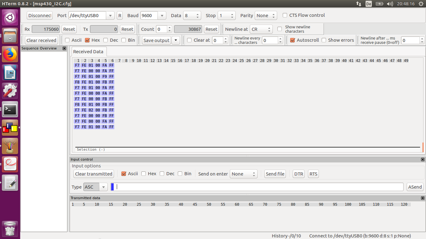
Screenshot eines Terminal-Programms mit seriellen Daten
Show errors Newline after ... ms receive pause (0=off) 0 Received Data 1 2 3 4 5 6 7 8 9 10 11 12 13 14 15 16 17 18 19 20 21 22 23 24 25 26 27 28 29 30 31 32 33 34 35 36 37 38 39 40 41 42 43 44 45 46 47 48 49 F7 FE 01 00 FA FF F7 FE 00 00 FA FF F7 FE 01 00 F9 FF F7 FE 01 00 FB FF F7 FE 00 00 FA FF F7
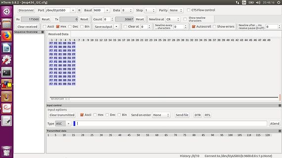
-
 Bild
Bild
Schaltplan eines Netzteils
01x03 C14 2.2uF C20 2.2uF C21 2.2uF C8 22mF C9 22mF C10 22mF D3 MBR745 D4 MBR745 D5 MBR745 D6 MBR745 C13 22mF GND RV1 1K RV2 1K R9 1K5 C7 330uF / 50V D2 1N4002 R11 1K C5 10uF R12 22 / 2W U2 LM337_TO220 VI VO R13 4K7 Q4 B8139 R14 470 / 2W R16 0.1 / 5W Q8 TIP2955G R18 0.1 / 5W D6 TIP2955G
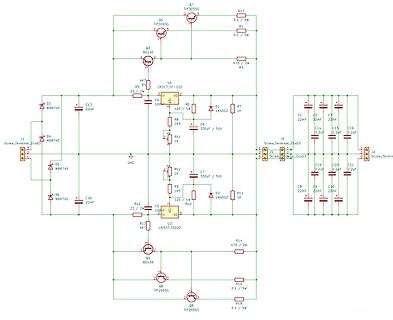
-
 Bild
Bild
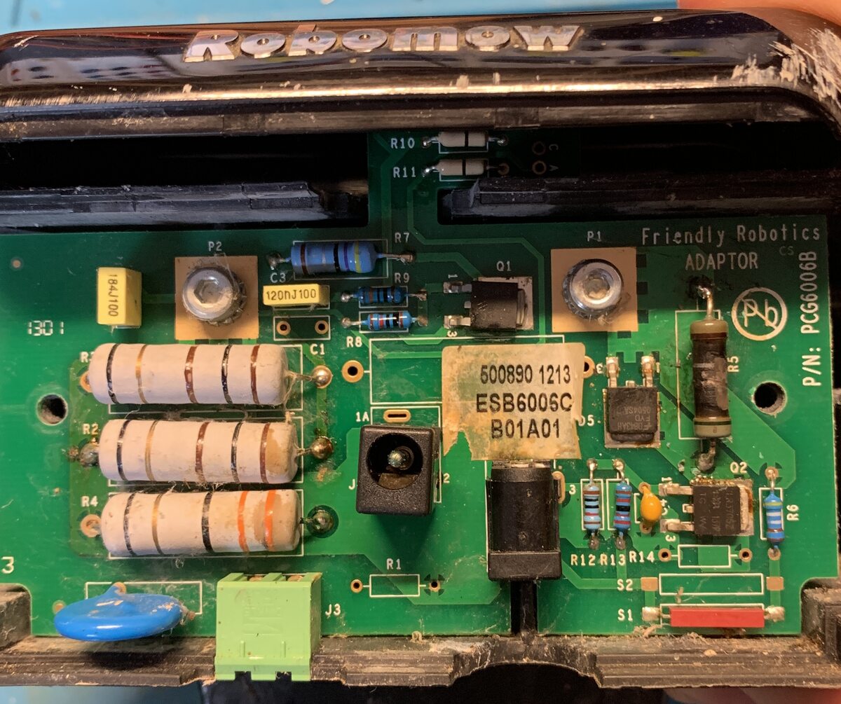
Innenansicht eines Netzteils auf Leiterplatte
ADAPTOR Pb P/N: PCG6006B R7 R9 01 C1 R8 500890 1213 ESB6006C B01A01 1A 05 R5 R2 R4 1A J 2 R1 R12 R13 R14 02 R6 3 J3 S2 S1
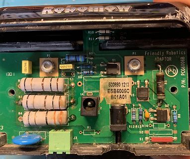
-
 Bild
Bild
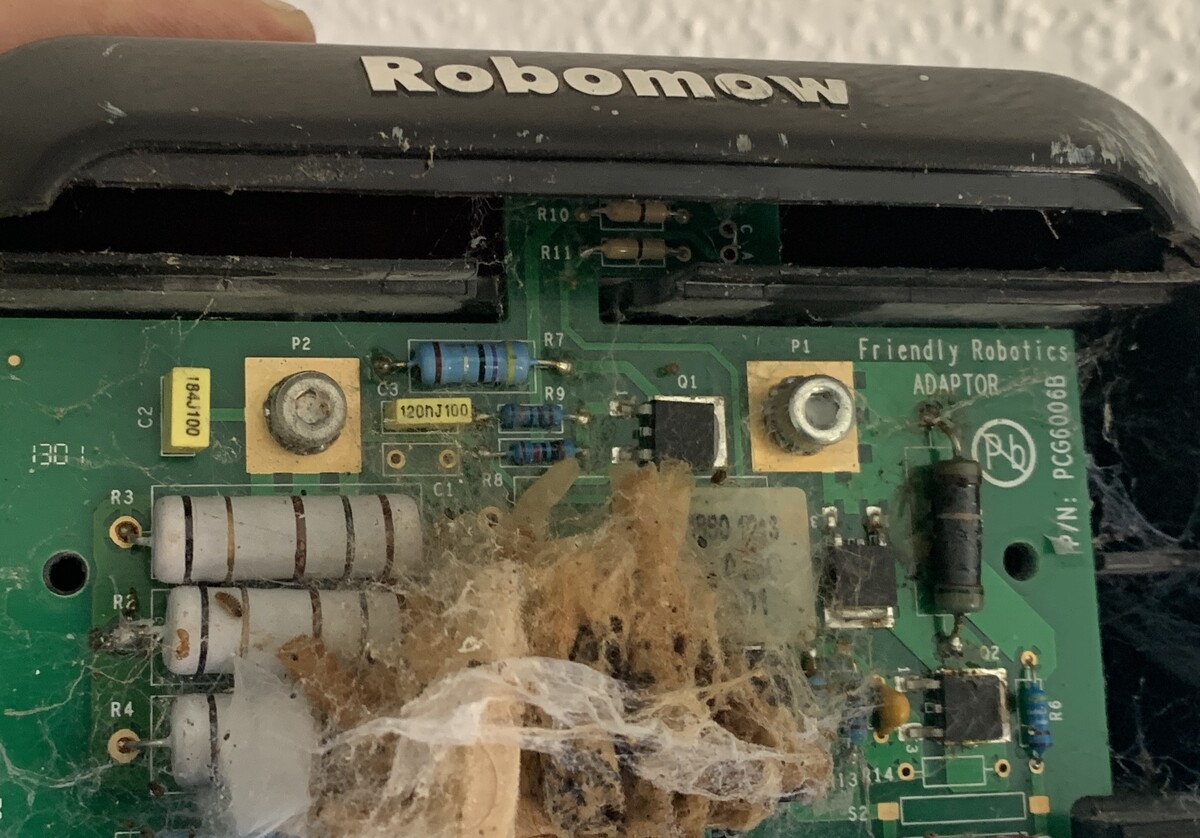
Verschmutzte Leiterplatte eines Robomow Adapters
R11 P2 184J100 C3 120HJ100 R7 P1 Friendly Robotics ADAPTOR Q1 Pb P/N: PCG6006B R9 C1 R8 R3 R2 R4 R6 13R14
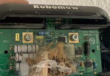
-
 Bild
Bild
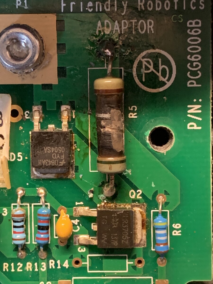
Nahaufnahme einer Leiterplatte mit Bauteilen
Friendly Robotics ADAPTOR CS Pb P/N: PCG6006B R5 D5. 0504SA FYD DB43AH Q2 R6 1R3705Z 1G W R12 R13 R14

-
Thread
Symetrisches Netzteil will nicht mit LM317/337
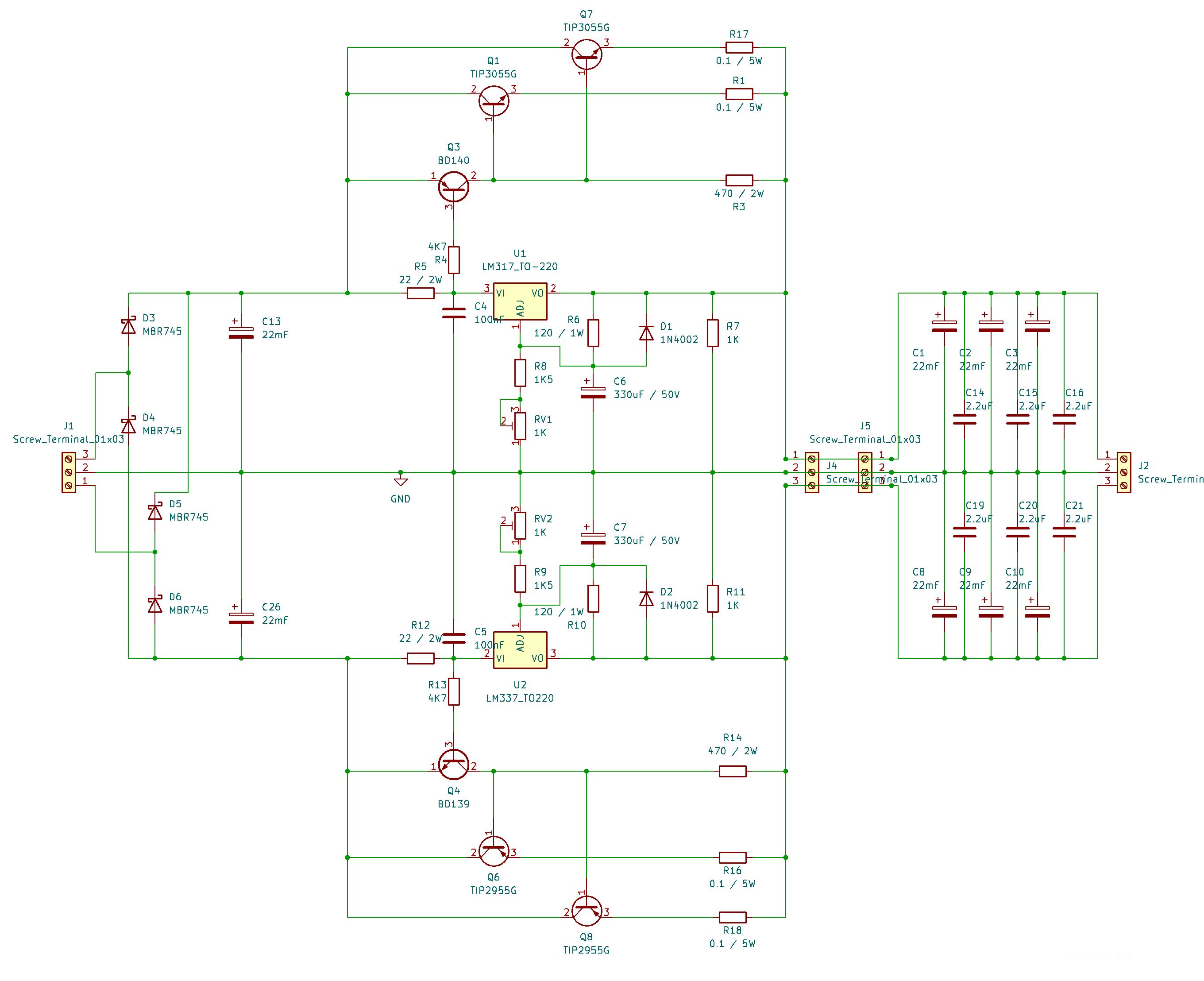
dann wie hier angeraten, die > Transistoren mal auslöten und ... Viel zu umständlich. Es reicht R13 herauszunehmen oder Q4 zwischen Emitter und Basis niederohmig zu verbinden oder den R12 mit einem viel kleineren Widerstand zu überbrücken oder R12 ganz zu brücken. Aber keine Lasten dranhängen die den
-
 Bild
Bild
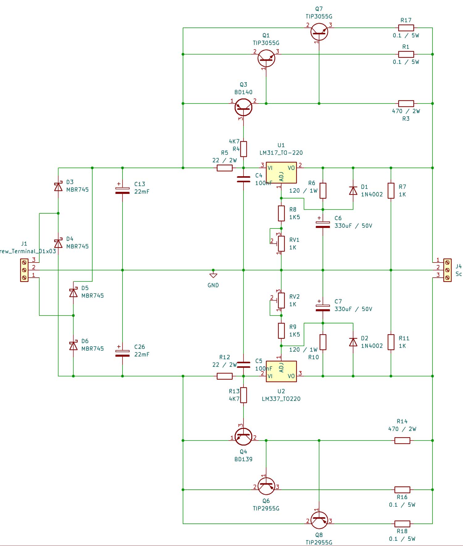
Schaltplan eines symmetrischen Spannungsreglers
1N4002 R7 1K C6 330uF / 50V R8 1K5 RV1 1K J4 Sc D3 MBR745 D4 MBR745 D5 MBR745 D6 MBR745 C26 22mF C13 22mF GND RV2 1K R9 1K5 C7 330uF / 50V D2 1N4002 R11 1K R12 22 / 2W C5 100nF R10 U2 LM337_T0-220 VI VO R13 4K7 Q4 BD139 R14 470 / 2W Q6 TIP2955G R16 0.1 / 5W Q8 TIP2955G R18 0.1 / 5W
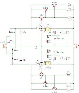
-
 Bild
Bild
Foto einer bestückten Leiterplatte mit Markierungen
H13W14E, R8, C7, C2, R10, C11

-
 Bild
Bild
Foto einer grünen Leiterplatte mit elektronischen Bauteilen
H13W14E R8 R4 R6 C7 C2 C1

-
 Bild
Bild
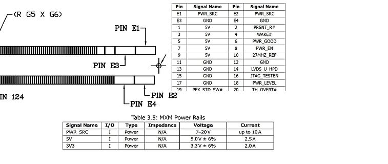
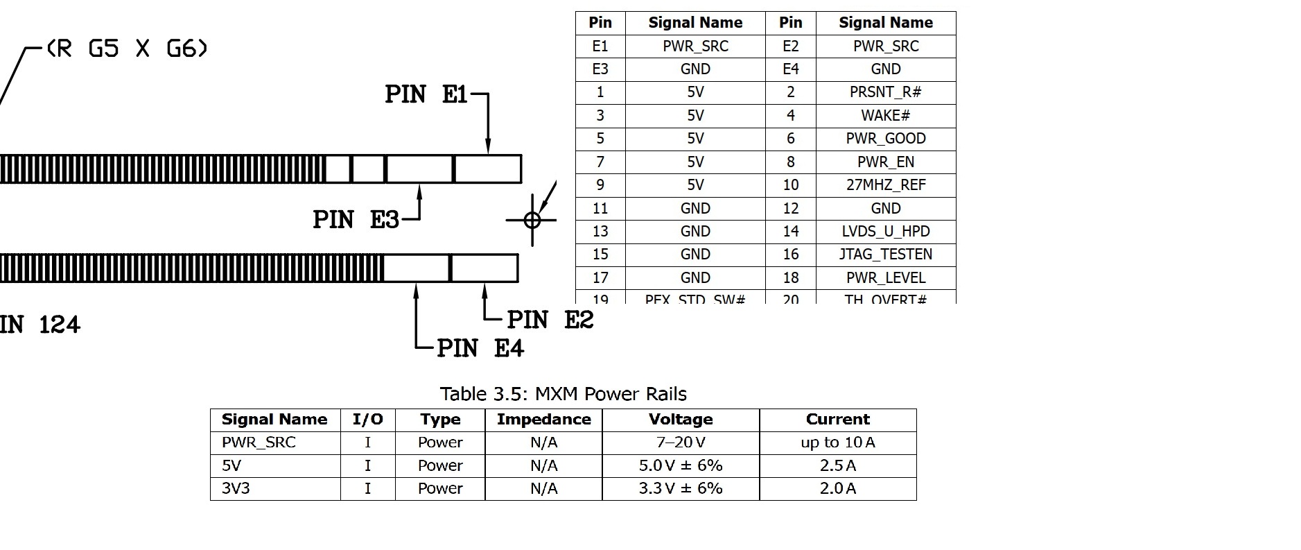
Pinbelegung und Tabelle der MXM Power Rails
E4 GND 1 5V 2 PRSENT_R# 3 5V 4 WAKE# 5 5V 6 PWR_GOOD 7 5V 8 PWR_EN 9 5V 10 27MHZ_REF 11 GND 12 GND 13 GND 14 LVDS_U_HPD 15 GND 16 JTAG_TESTEN 17 GND 18 PWR_LEVEL 19 PFX STD SW# 20 TH OVERT# Table 3.5: MXM Power Rails Signal Name I/O Type Impedance Voltage Current PWR_SRC I Power N/A 7-20 V up to 10 A