den Ausgang vom MP abzuschließen ist nicht gut. Das sind Transistorausgänge die vieleicht mal 20-30 mA schaffen. Den Ausgang auf nen ULN2803 oder ähnlich dann, wenn es denn ein Relais sein muss daran dass Relais. Ich würde da aber nen Optokoppler vorsehen. Und dann auf den Rasphy.
Thomas S. schrieb im Beitrag #7587724: > Das sind Transistorausgänge die vieleicht mal 20-30 mA schaffen Woher weißt du das?
mfgVers, byte interrupt); // Used for Decoder void SetupMonitor(byte interrupt); // Used when building a monitor // All packets are sent to RawPacketHandler. Return true to stop dispatching to other handlers. void SetRawPacketHandler(RawPacket func); // S 9.2 defines two special packets. Idle and reset.
"101" ist wie Widerstände markiert, 2 Ziffern und 1 Anzahl der Nullen (= 10^x), sollte also 100µH sein. Die Größe ist eher klein, Reichelt hat eher 12mm Durchmesser: https://www.reichelt.de/fest-induktivitaeten-radial-c3180.html?ACTION=2&GROUPID=3180&START=0&OFFSET=100&nbc=1&SID=9287a89daf4f151446ae48f4aab07db41bcb19c007d7d258c6846 da ist aber einer mit 103 beschriftet, wohl ein Fehler des Katalogs. unter "mehr Filter" kann man auf 100µH beschränken, immer noch 7 Fundstellen. den
= −2 A; CE = −1 V; see Fig.2 40 − − VCEsat collector-emitter saturation voltCge I = −B A; I = −0.2 A − − −0.5 V VBE base-emitter voltage C = −5 mA; VCE= −10 V − −600 − mV C = −2 A; CE = −1 V − − −1.2 V T transition
= 5 mA; VCE = 10 V 50 − − VCEsat collector-emitter saturation voltaIC= 2 A; B = 0.2 A − − 0.5 V VBE base-emitter voltage IC= 5 mA; V CE = 10 V − 0.6 − V IC = 2 A; CE = 1 V − − 1.2 V T transition frequency IC
PJ157 PJ158 PJ159 +5DSP AV1_D AV2_D 1 DGND 2 AV4_D DGND W111B W117B PHR E B 3 SRL 7 W SRE 7 IPL C A 1 1 IPE 5 + - OPERATION (2) XML 3 (CB452) XMR USBL MAIN (1) USBR CB101 (CB158) UTUL OUTIC102IN 1E E1 TUR W101A W104A _ _ TUE COM A A BLW111A BL BU BU RE RE MAIN (2) MIC IN W105A W103A W102A (CB102) E
SDIO NC PIU720 1 PU?06 SDO NC PIU?02 1 1 _ 2 2 GND VCC_3V3 NC 86680?UIP 3 S D 4 5 6 7 4 0 1 2 1 1 A S D_ _ PI PU?07 PIU?07 A S D A A A A C B B B B B C S D R? GND I/ORESET NC 93 P V V P P P P P P P P P P V V V NC 390?UIP P 10K PU?06 OSK NC PIU?07 7 8 9 0 1 2 3 4 5 6 7 8 9 0 1 2 R? DRCTKC PI NC 98890
hat in ArgoUML alle Klassen seiner Software in eine große Zeichnung gequetscht. Ausgedruckt locker A1 oder gar A0. Alle Felder der Klassen waren aufgeführt, aber das wichtige, die Beziehungen der Klassen untereinander, gingen unter. Man sieht dann den Wald vor lauter Bäumen nicht.
selber dass sie überflüssig sind: https://www.reddit.com/r/scrum/comments/18kiudx/feel_useless_as_a_scrum_master/?tl=de
so that a 4.0 V p-p EXE input produces a A −30 G 5.12 V p-p output when using a 6 V supply. −40 The ADG1612 has a typical on-resistance of less than 1 Ω and is idealforthegainswitch.However,becausetheoffcapacitance
unless otherwise noted) PARAMETER CONDITIONS SYMBOL TYP MAX UNIT (1) Forward voltage per diode IF=50A, J = 25°C VF - 0.55 V (2) Reverse current @ ratedRV per diode TJ= 25°C R - 500 µA Junction capacitance 1 MHz, V =4.0V C 2.7 - nF R J IF=0.5A R I =1.0A Reverse recovery time IRR0.25A rr 150 - ns Notes
contains ESD protection and exceeds the following tests: Human Body Model (HBM), 2000 V, Class 2, JESD22 A114−C Machine Model (MM), 200 V, Class B, JESD22 A115−A Charged Device Model (CDM), 2000 V, Class IV, JESD22 C101−C 3. Low duty pulse techniques are used during test to maintain junction temperature as
Verkaufe hier ein LPRO-101 Rubidium-Frequenznormal von EFRATOM. Ausgang: 10.000.000,0 Hz Sinus Gestestet und voll funktionsfähig. Der Oszillator rastet nach ca. 3:30 ein. Betriebsspannung 24V und ca. 1,6A in der Aufwärmphase
10 MHz abweichende > Frequenzen erzeugen. Der Nachteil war ein höherer Phasenjitter, das > LPRO-101 liefert reinere Signale Die Phase mit den billigen LPRO-101 ist an mir leider vorbeigegangen ohne das ich davon etwas Mitbekommen habe. Die etwas spätere Phase mit den FE5680A habe ich wirklich so
Datenblatt durch, ist wichtig. Gibts für alle Marken 18650. Z.B. gibt es welche die kann man nur mit 3A belasten, welche mit 10A 20 und 30A.
(prx) A. K. schrieb im Beitrag #7566776: > Der G. schrieb im Beitrag #7566717: >> AE kann von >> deutschen Gerichten belangt werden. Also können bei Schäden genauso gut >> AE + Verkäufer haftbar gemacht
VDD33 PI12P10 E_VGL PI J1024 J11 VDD5V CO1 E_GDR 23 PIN24 FPC0.5-SMT-24P U B5819W SL PI PI J1023 PIN23 A PIU102 CO1 E_RESR PI J1022 A 3 VOUT 1 SOD323 PI 21 PIN22 PIU103 VIN GND PIU101 P3 1uF C22 PI J1021 PIN21 CO3 DD 0402 PI0 P2 PI J1020 PIN20 PICO4 P C5 ME6216A33XG P3 19 10uF IPPI2 1uF PI J1019 PIN19 PI
BF101 Wie heißen die internationalen Notzeichen derSatellitenkommunikation? außerhalbdesAmateurfunks? A Maydayund SOS A Senderichtungvom Satelliten zur Erde B Securité und Distresse B Senderichtungvon der
Characteristics (Desktop Only) Power Plane Maximum Power Consumption Symbol S0 S3 S4/S5 G3 V5REF 2 mA N/A N/A N/A V5REF_Sus 2 mA 1 mA 1 mA N/A Vcc3_3 308 mA N/A N/A N/A VccSus3_3 212 mA 53 mA 53 mA N/A 6 VccHDA 32mA N/A N/A N/A VccSusHDA 32 mA 1 mA 1 mA N/A 6 VccGLAN3_3 1 mA N/A N/A N/A VccGLAN1_5 80
, 25s(typ.) for 32Mb, and 50s(typ.) for 64Mb • Low Power Consumption - Low active read current: 25mA(max.) at 86MHz, 20mA(max.) at 66MHz and 10mA(max.) at 33MHz - Low active programming current: 20mA (max.) - Low active erase current: 20mA (max.) - Low standby current: 20uA (max.) - Deep power-down
funktionieren (nicht gleichzeitig, sondern entweder/oder). Die Frage ist also: reichen denen 800mA auf der 3.3V-Schiene?
Industrial/D344x-S/Documentation/ gibt es Infos, unter Specification gibt es eine pdf GPIO_Chip_PCA955a.pdf. Hier: http://www.sp-it.net/index.php?option=com_content&view=article&id=1409&Itemid=101&jsmallfib=1&dir=JSROOT/drivers/fujitsu/Products/Mainboards/Industrial-und-ExtendedLifetime/D3402-B_D3417
regex101.com sagt zu Ausdruck A: +-. matches a single character in the range between + (index 43) and . (index 46) (case sensitive) ',' ist index 44.
Klaus P. schrieb im Beitrag #7564006: > regex101.com sagt zu Ausdruck A: > > +-. matches a single character in the range between + (index 43) and . > (index 46) (case sensitive) Klar, das ist halt die normale Funktionalität des "-" in solchen
in VHDL erstellt wurde und in mehreren Ausbaustufen verwendet wird. Die Berechnungsformeln wurden u.a. in MATLAB umgesetzt und in lineares VHDL gewandelt. Daraus ergeben sich je nach Komplexität des Modells die anwendungsabhängige Anzahl von Rechenschritten. Der Bedarf ist als grober Anhaltspunkt zu
Analogsynthesizer 7.184 15.165 55.190 213.950 2.590.700 8-fach polyphoner Synthesizer mit Filtern 47.580 101.600 366.700 1.426.400 17.870.000 Anmerkungen. Diese Tabelle ist effektiv das Ergebnis der Verknüpfung der beiden vorherigen Tabellen unter Anrechnung der Anzahl der beteiligten Bauelemente und dem offset
Pinecil, TS80, TS100 und TS100 - Da sind die Spitzen allerdings ein bisschen teurer. Ich hab den TS101, weil nicht nur USB-C, sondern auch Netzteilbetrieb möglich ist und so für normale Arbeiten macht das Ding tatsächlich Spaß. USB-PD ist nun auch nicht Unübliches mehr. Mit dem KETS02 hab ich keine
Sehr seltsam, da scheints doch Unterschiede zu geben. Bei meinem Test mit nem 19V 4,xA Netzteil über USB-PD gabs überhaupt keine Probleme. Ich weiss jetzt aber nicht mehr, ob ich da nur das mitgelieferte Messer probiert hab, oder auch eine Originalspitze. Etwas störend finde ich die fehlende
Baseboard. When the DC input voltage is unavailable the whole Limestone board is powered by the battery. A dedicated battery management hardware including a charger and a fuel gauge handles the switching of the power sources (SUPPLY+). A direct supply to the battery (BATT+) is also provided and routed to
Operating Temperature Range Vdd = 1.5V - 3.63V, ≤30 mins 125 °C Human Body Model ESD Protection HBM,JESD22-A114 3000 V Charge-Device Model (CDM) ESDProtection JESD220C101 750 V Machine Model (MM) ESDProtection TA= 25°C 300 V Latch-upTolerance JESD78 Compliant Mechanical ShockResistance Mil 883, Method 2002
Mischpult. "Invertierender Addierer/Summierverstärker" https://de.wikipedia.org/wiki/Operationsverst%C3%A4rker#Invertierender_Addierer/Summierverst%C3%A4rker Vermutlich gibt es EC-Mikrofone, die besser und welche, die schlechter für Dein Vorhaben geeignet sind. https://de.wikipedia.org/wiki/Elektretmikrofon
Entwurf ist ein Mix aus https://www.mikrocontroller.net/topic/494421, https://www.ti.com/lit/an/sboa290a/sboa290a.pdf, und https://www.ti.com/lit/ug/tidu765/tidu765.pdf (welches wirklich genial ist). Als OPAmp, der als Transimpedanzwandler läuft, fiel die Wahl auf den OPA992 (bzw. dessen quad Variante
(prx) A. K. schrieb im Beitrag #7555805: > Stehzeugen Das Wort gefällt mir:-)
(prx) A. K. schrieb im Beitrag #7560952: > Cha-woma M. schrieb im Beitrag #7560950: >> Naja, schon zu Zeiten wo es nur Pferde gab um sich von A nach B fahren >> zulassen (oder zu reiten) gab es erhebliche
knolleary/PubSubClient@^2.8 Fehlermeldung: Error: target_hash 000...000 Error: file_hash: a1108e...9dcd9c Target is already running an algorithm Failed to start algorithm (-4)! PROF: Flash verified in 101.936 ms **** Verification failure! **** target_hash 000...000 file_hash: a1108e...9dcd9c ** Verify Failed ** .pioinit:12: Error in sourced command file: Protocol error with Rcmd [/code] Habt ihr eine Tip was die Ursache für diesen Fehler sein kann. Gibt es JTAG
ein S10K275 sein, oder? Wäre der hier der richtige: https://www.pollin.de/p/tdk-varistor-b72210s0271k101-s10k275-2500a-350v-dc-275v-ac-222376 Kann ich auch ohne den Varistor die Platine einfach mal anschließen?
10mm Raster: https://www.pollin.de/p/tdk-varistor-b72220s0271k101-s20k275-8000a-350v-dc-275v-ac-222397 https://www.pollin.de/p/tdk-varistor-b72220p3271k101-s20k275e3k1-12000a-350v-dc-275v-ac-222388 Knut schrieb im Beitrag #7551658: > Kann ich auch ohne den Varistor
(ESD) Electrostatic discharge V Charged device model (CDM), per JEDEC specification 0 1500 JESD22-C101, all pins (2) (1) JEDEC document JEP155 states that 500-V HBM allows safe manufacturing with a standard ESD control process. (2) JEDEC document JEP157 states that 250-V CDM allows safe manufacturing
ESDA/JEDEC JS-001 ±4000 V(ESD) discharge Charged device model (CDM), per JEDEC specification JESD22-C101 (2) ±1500 V (1) JEDEC document JEP155 states that 500-V HBM allows safe manufacturing with a standard ESD control process. (2) JEDEC document JEP157 states that 250-V CDM allows safe manufacturing with
operations r s MCB Protected short-circuit withstand u c d v Prospected short-circuit current rms 1kA 3kA 1kA 3kA 3kA 3kA 1kA M D MCB C40- MCB C63- 6A 10x38 gG Associated protection MCB C16-6kA MCB C25-6kA MCB C16-6kA MCB C25-10kA 10kA Fuse Power dissipation Power dissipation per current path 1W 1.5W
Gehäuse damit... SD Karteninfos wurden jetzt auch in die "mem" Anzeige übernommen. [code] 10 FOR A=0 TO 10 20 FOR B=0 TO 255 30 AWRITE 12, B 40 DELAY 10 50 NEXT B 60 FOR B=255 TO 0 STEP -1 70 AWRITE 12, B 80 DELAY 10 90 NEXT B 100 NEXT A [/code] Mit diesem kleinen Programm lässt sich
für die SD Karte [code] // v0.19: 04/12/2023 // added Modulo function // PLOT x,y: setting a pixel // DRAW x1,y1,x2,y2: drawing a line // BOX x,y,h,w,c1,c2: drawing a box // KEY(): returns the pressed key // SIN(), COS() functions // CHR() // TOP(): returns the location aftzer the
Coeff. Reverse Zener current (2) Zener Voltage of Zener Voltage Voltage at at at at at at at IZ= 5 mA Z = 5 mA IZ= 1 mA IZ= 5 mA f = 1 kHz f = 1 kHz IR= 100 nA Tamb = 45°C T amb = 25°C Type VZ(V) zj( ) rzj ) vz (10 /K) VR(V) IZ(mA) Z (mA) ZPD1 (3) 0.7 ... 0.8 6.5 (< 8) < 50 –26 ... –23 – 280 340 ZPD2.7
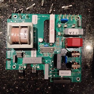
also noch nicht konstant. Ich muss ja die Kondensatoren 601 und 602 tauschen, im besten Fall auch C101 -C104. Da ich bei den Teilen aber nicht richtig durchblicke, wollte ich nachfragen, ob ich mit diesen richtig liege. 2 Stück https://www.conrad.de/de/p/wima-mkx2aw38206a00kssd-mkp-x2-funkentstoer-kondensator-radial-bedrahtet
Gleichrichter (Die waren ursprünglich defekt) - C601 und C602 mit 1nF 2kV ersetzt. (ursprünglich 470pF) - CX101-CX104 alle mit 680nF X2 305VAC/630VDC 20% ersetzt - Drosseln LF101 und LF102 mit 49uH 5.8A 20% ersetzt Drosseln: https://www.mouser.ch/ProductDetail/Wurth-Elektronik/744132?qs=Cb2nCFKsA8rwtymtQ8%

 Bild
Bild
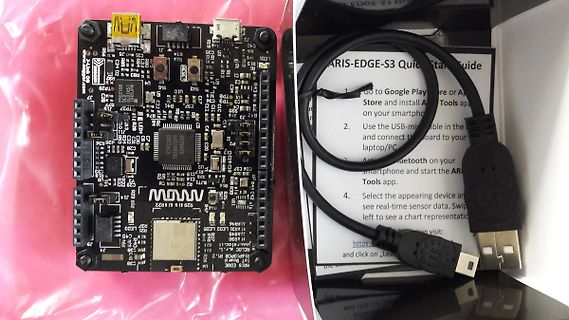
 Bild
Bild
 Bild
Bild