output overvoltage condition. If the output voltage is greater than approximately 7 V, the emitter-base junction of the series-pass element (internal or external) could break down and be damaged. To prevent this, a diode shunt can be used as shown in Figure 2 Man sollte halt schon ALLES lesen und
> das sagte "1000h Lifetime" o.ä. Ja, das irritiert die meisten Einsteiger. Es ist nur so das 85°C Elkos für Temperaturen bis 45°C Umgebungstemperatur verwendet werden und 105°C Elkos für ergöhte Anforderungen mit bis zu 75°C. Die 85/105°C sind noch ein Relikt aus dem Röhrenzeitalter, solche Quasisstandarts
drives ID90 TC= 90°C 95 A in battery supplied equipment IF25 TC= 25°C (diode) 130 A I T = 90°C (diode) 85 A Features F90 C MOSFETs in trench technology: -low RDSon -optimized intrinsic reverse diode Symbol Conditions Characteristic Values (TVJ= 25°C, unless otherwise specified) package: min. typ. max. -high
110V. Daher habe ich die beiden Netzwickungen 2x110V parallel geschaltet. Gab der Trafo her. War ein M85(b)? Habe das mit 12Volt betrieben. Hier muss man mit der Totzeit aufpassen. Ohne Last am Ausgang gibt es schnelle Spitzen in den Schaltpausen. Die killen dann die FETs oder dein Netzteil. Soo einfach
als 1k sein, sonst müsstest Du tatsächlich noch die BD139 und BD140 davorschalten und zwischen den Basen 6 Dioden schalten statt nur 4 Dioden. Durch den 1µF Kondensator hast Du in Verbindung mit der Trafoinduktivität versehentlich einen Parallelschwingkreis mit einer zu hohen Resonanzfrequenz gebaut
0 5 12 mV Positive FB Pin Bias Current V FB= Positive Feedback Voltage, Current Into Pinl 81 83.3 85 μA Negative FB Pin Bias Current V FB= Negative Feedback Voltage, Current Out of Pin 81 83.3 85.5 μA Error Amplifier Transconductance 230 μmhos Error Amplifier Voltage Gain 70 V/V Quiescent Current V SHDN
to 85 431AI & no Sb/Br) TL431AIDRG4 ACTIVE SOIC D 8 2500 Green (RoHS CU NIPDAU Level-1-260C-UNLIM -40 to 85 431AI & no Sb/Br) TL431AILP ACTIVE TO-92 LP 3 1000 Pb-Free CU SN N / A for Pkg Type -40 to 85 TL431AI
else range (value, std::forward<Rest> (rest)...); } int main() { try { int value = 85; range (value, 50, [&] () { std::cout << "Keine 50\n"; }, 80, [&] () { std::cout << "Keine 80\n"; }, 90, [&] () { std::cout << "Keine 90\n"; } ); } catch (const std:
Allerdings hat mich das ISO-Dokument eines Besseren belehrt: [pre] void open(const string& s, ios_base::openmode mode = ios_base::in); void open(const filesystem::path& s, ios_base::openmode mode = ios_base::in); Effects: Calls open(s.c_str(), mode). [/pre] Daraus geht hervor, dass der
monatsgenau justierbar. Ganz nach Bedarf kann man auch von > Premium auf Standardversion (nur 17,85 monatlich!) zurückschrauben. Das > sollte für einen mittelständischen Betrieb doch kein Problem sein. > Größere dürften sowieso mit anderer Software arbeiten. > Wir wissen was es kostet. Wir reden
monatsgenau justierbar. Ganz nach Bedarf kann man auch von > Premium auf Standardversion (nur 17,85 monatlich!) zurückschrauben. Das > sollte für einen mittelständischen Betrieb doch kein Problem sein. > Größere dürften sowieso mit anderer Software arbeiten. Was du hier beschreibst (obige Zitate
CAN-Interface-Gassensor für die Analyse von Lithium-Ionen-Zellen. Honeywell schickt ein - in Hunderterstückzahlen rund 85 Euro kostendes - Bauteil ins Rennen, das auf die Bedürfnisse der Elektromobilität optimiert ist. Der BAS6C enthält in CAN-Interface, über das er über die im Gehäuse integrierten „Gas-Sensoren“ informiert
Wohingegen der Infineon Motortreiber "BTN8962TA" einen HS/LS continuous drain current von 30A bei TC < 85°C aufweist. Link @farnell: http://at.farnell.com/infineon/btn8962ta/motortreiber-halbbr-cke-to263/dp/2470126/false Link @manufacturer: http://www.infineon.com/cms/de/product/power/motor-control-and-gate-driver-ics
500Vdc 6 Input-Output Capacitance CI-O 0.6 pF f = 1 MHz;V I-O= 0Vdc 6 Notes: 1. Derate linearly above 85°C free-air temperature at a rate of 0.25 mA/°C. 2. Derate linearly above 85°C free-air temperature at a rate of 0.30 mA/°C. 3. Derate linearly above 85°C free-air temperature at a rate of 0.375 mW/°C. 4. Derate linearly above 85°C free-air temperature at a rate of 1.875 mW/°C. 5. CURRENTTRANSFER RATIO in percent is defined as the ratio of output collector current, I , to the forward LED input current, I , times 100. O F 6. Device
MIN. 5 V/µs VTM TM = 16 A tp = 380 µs Tj = 25°C MAX. 1.6 V V t0 Threshold voltage Tj = 125°C MAX. 0.85 V R d Dynamic resistance Tj = 125°C MAX. 46 m I Tj = 25°C MAX. 5 µA DRM V = V R = 220 I DRM RRM GK Tj = 125°C 1 mA RRM STANDARD Symbol Test Conditions TN805 TN815 TYNx08 Unit I MIN. 0.5 2 2 mA GT VD=
-40 C to +85C° Industrial GD32E230G8U6 64 QFN28 Green -40 C to +85C° Industrial GD32E230G6U6 32 QFN28 Green -40 C to +85C° GD32E230G4U6 16 QFN28 Green Industrial -40 C to +85C° Industrial GD32E230F8V6 64 LGA20 Green -40 C to +85C° Industrial GD32E230F6V6 32 LGA20 Green -40 C to +85C° GD32E230F4V6 16 LGA20 Green Industrial -40 C to +85C° Industrial GD32E230F8P6 64 TSSOP20 Green -40 C to +85C° Industrial GD32E230F6P6 32 TSSOP20
davon, 494 und Regelschleife >> fehlt hierbei). > > Sehe ich das richtig, die ziehst die beiden Basen von Q1/Q2 einfach auf > Null zum Abschalten? Und wo bleibt dann die Energie, die noch in Lin > steckt? Sorry, aber so kannst du so einen Resonanzwandler nicht steuern. > Es bleibt nichts, du musst
Wickeldaten: 9 Windungen Primär. Sekundär 1: 0,30mm zu 25,5mm, 85 wdg. Zweilagig mit mittelabgriff nach der ersten Lage. 170 wdg. Gesamt. Sekundär 2: 0,30mm zu 22,5mm, 75 wdg. Zweilagig 150 wdg. Gesamt ohne mittelabgriff. Sekundär 3: 0,30mm mit 89 Windungen
Ruhestrom stellst Du nicht mit der Konstantstromquelle ein, sondern durch die Spannung zwischen den Basen bzw. Gates der komplementären Ausgangstreiber. Das macht man üblicherweise mit einer Schaltung namens "VBE multiplier" bzw. "amplified diode", im Prinzip eine Konstantspannungsquelle mit Transistor
#3353209: > Was hat's denn nun mit dem Phasenrest auf sich? Die Phasenreserve ist groß genug (etwa 85° bei 600kHz) > Kann man das jetzt so lassen? Sehr schlecht ist die Überhöhung bei einigen MHz, aber viel besser wirst du es mit den Transistoren nicht hinbekommen. Die Leerlaufverstärkung ist zu
to indirect memory and 2 post-increment source pointer by 2 MOV Rw, Move indirect word memory by base plus constant to 4 [Rw + #data16] direct GPR MOV [Rw + #data16], Move direct word GPR to indirect memory by base plus 4 Rw constant Semiconductor Group 28 SAB 80C166W/83C166W Instruction Set Summary
option modules - Standalone Applications contain a high-performance microprocessor that allows the base drive to be dedicated to motion control as well as • Motion Control Functionality machine control. - Velocity, Torque Mode - Position-Indexing - Synchronization, Electronic Gearing SM-EZMOTION - CAMS
DB DataBase DB Datenbank DB Datenbestand DB Datenbus DB Dauerbelastung DB Dauerbetrieb DB Denitrifikationsbecken [Technik] DB Deutsche Bahn DB Deutsche Bank DB Deutsche Bibliothek DB
Hi, danke. Bin immer irgendwie bei ATtiny25/V / ATtiny45/V / ATtiny85/V hängen geblieben... Gruß Rainer
the strengths of two industry leading GPS integrated circuits: The STMicroelectronics STA2051 GPS base-band chip with embedded ARM processor, RAM and Flash coupled to the low-power and small-sized SiGe SE4100L GPS RF down-converter. The results are complete, ultra-low power consumption modules that perfectly
Efficiency Red 2.0 2.5 vF Forward Voltage Green 2.2 2.5 V IF=20mA Yellow 2.1 2.5 Super Bright Red 1.85 2.5 R Reverse Current All 10 uA VR = 5V Absolute Maximum Ratings at T =25°C A High Super Parameter Bright Red Efficiency Green Yellow Bright Units Red Red Power dissipation 120 105 105 105 100 mW DC
Unit: mm LAND PATTERN (REFERENCE) ▓ STRUCTURE ILLUSTRATION PART NAME MATERIAL PART NAME MATERIAL 1. BASE CERAMIC 4. ELECTRODE Metal 2. LID KOVAR 5. ADHESIVES SILVER GLUE 3. BLANK QUARTZ ▓RELIABILITY SPECIFICATION REFER TO JIS C 6701 1. ENVIRONMENTAL PERFORMANCE ITEM CONDITION 1. HIGH TEMPERATURE STOREDAT 85±2℃ FOR 720±12H. ( If Customer's temperature request STORAGE is higher than the standard,Temperature test must be done for customer requirements. ) THEN 25±2℃ OVER 2H BEFORE TESTING. 2. LOW TEMPERATURE
Fehlermeldung: [c] für crc1(a): crc1 = crc1 ^ int(a[i],16) ValueError: invalid literal for int() with base 16: '\x08' bzw. für crc2(a): crc1 = crc1^int(a[i]) ValueError: invalid literal for int() with base 10: '!' [/c] Was läuft da falsch?!? [c] def crc1(a): try:
zwischen verschiedenen Kameras auch weich überblenden. Irgendwann gab es dann sog. digitale Time Base Correctors, d.h. Bildspeicher, mit denen sich Phasen- und Frequenzunterschiede asynchroner Videoquellen wieder ausbügeln ließen.
Empfänger sind ja (logischerweise) vorhanden: [code] NEC type remote controllor - IR Time Base Param is 71 Tolerance is 533 Period is 30833 [/code] -------------------- Karte entfernt: [code]Card Out - SD SystemCardEventSet - Out 0x00008000 MCardEventProcess - MCardEvent 4, Card
Version MC/Air Grid optimized for medium concentration + Antireflective Coating adapted to air X 250 3,85 3,06 3,77 2,80 10,59 89,9% 42,1 X 500 7,66 3,11 7,54 2,81 21,20 88,9% 42,0 X 1000 15,35 3,15 15,07 2,69 40,56 83,8% 40,3 Version MC/Glass Grid optimized for medium concentration + Antireflective Coating
Während der Ausbildung ('87) hatten wir im Computerkabinet KC85-2 mit Basic Interpreter, der von Kassette vorher ins RAM geladen wurde. Ich hatte mir einen einfachen Hex-Editor geschrieben, wo ich mir ganze Speicherbereiche anzeigen lassen konnte. Mein besonderes
sondern schraube meines klassisch > an der Wand fest. Da weiss ich immer, wo es ist. Viele DECT-Basen besitzen einen Knopf, um die eingebuchten Mobilteile klingeln zu lassen.
Voltage Input Wide Range Input PART Single Voltage Input Wide Range Input ORDER 100/115/230 VAC ±15% 85 to 265 VAC 100/115/230 VAC ±15% 85 to 265 VAC P 4,6 P 4,6 ORDER P 5,6 P 5,6 NUMBER MAX MAX NUMBER MAX MAX TOP221Y 12 W 7 W TOP221P or TOP221G 9 W 6 W TOP222Y 25 W 15 W TOP222P or TOP222G 15 W 10 W TOP223Y
Albert M. schrieb im Beitrag #4911191: > Bist Du beim Senden von (0x85) auch im Jog-Mode? Das kann ich leider nicht beurteilen. Der letzte Befehl an GRBL vor dem 0x85 ist auf jeden Fall ein Jog-Befehl. Insofern nehme ich an, dass GRBL zu dem Zeitpunkt noch im Jog-Modus
vom Smartphone aus, weil er es nicht auspacken kann. Sinnvollerweise werden einfach *.c oder *.bas oder *.ino Dateien angehängt. Man kann auch mehrere Dateien anhängen... BTW: Weil Arduino Quelltext das selbe wie C ist, ist [c] der geeignete Token zum Formatieren.
Medical Equipment Gaming Machines PART TEMP RANGE PIN-PACKAGE Industrial Displays MAX6952EAX -40°C to +85°C 36 SSOP MAX6952EPL -40°C to +85°C 40 PDIP Pin Configurations appear at end of data sheet. SPI and QSPI are trademarks of Motorola, Inc. MICROWIRE is a trademark of National Semiconductor Corp. Typical
voltage for logic VCC/IOVCC -0.3 4.6 V Input voltage VIN -0.3 VCI+0.3 V Operating temperature Top -30 85 °C Storage temperature TST -40 85 °C Humidity RH - 90%(Max60 °C) RH Power Supply Voltage 2 VCI-AGND -0.3 4.6 V n ELECTRICALCHARACTERISTICS DC CHARACTERISTICS Parameter of DC Symbol Min Typ Max Unit characteristics
Empty "No data " // 48 Empty }; const /*PROGMEM*/ int tempis[] = { // Tempi for songs 120,140,108,140,85,80,70,140,140,140, // Values Song 1 - 10 Asa Branca, Take on me, Starwars,Cantina Band, Game of thrones, Fuer Elise, Greensleeves Silent night, Happy birthday, Nokia Ringtone 105,200,144,120,114,88,120,76,160,114
and that has a radiant intensity in that direction of 1/683 watt per steradian. 2.1.2 Symbols for base units The base units of the International System are listed in Table l which relates the base quantity to the unit name and unit symbol [10th CGPM (1954, Resolution 6; CR, 80); 11th CGPM (1960, Resolution
to 85 R1000I & no Sb/Br) TIR1000IPWG4 ACTIVE TSSOP PW 8 150 Green (RoHS CU NIPDAU Level-1-260C-UNLIM -40 to 85 R1000I & no Sb/Br) TIR1000IPWR ACTIVE TSSOP PW 8 2000 Green (RoHS CU NIPDAU Level-1-260C-UNLIM -40 to 85 R1000I & no Sb/Br) TIR1000IPWRG4 ACTIVE TSSOP PW 8 2000 Green (RoHS CU NIPDAU Level-1-260C-UNLIM -40 to 85 R1000I & no Sb/Br) TIR1000PSLE OBSOLETE SO PS 8 TBD Call TI Call TI 0 to 70 TIR1000PSR ACTIVE
implementation of the GSM/GPRS. C55/C55i features GPRS class B, class 10 (making download at speeds up to 85 kbps) and supports the GPRS coding schemes CS-1, CS-2, CS-3 and CS-4. The C55/C55i module incorporates all your needs to create high- performance GSM/GPRS solutions: base band processor, power supply
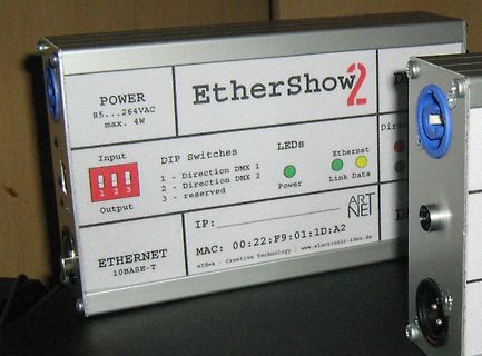
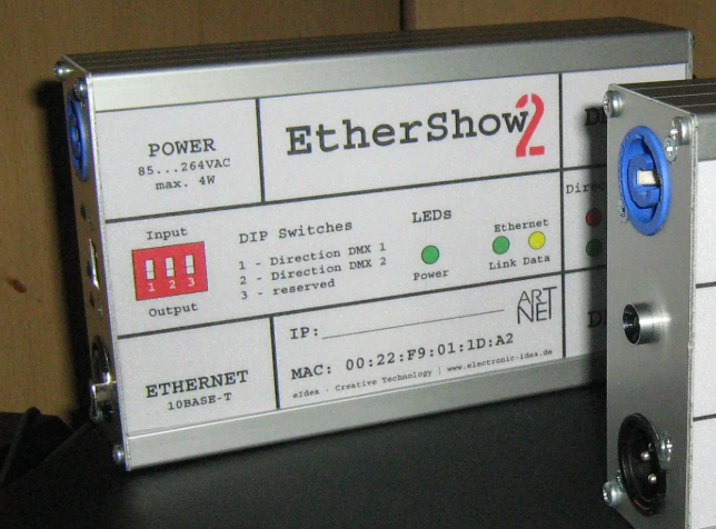
EtherShow2
POWER 85...264VAC max. 4W
Input DIP Switches Output
1 - Direction DMX 1
2 - Direction DMX 2
3 - reserved
LEDs Power Link Data
ETHERNET 10BASE-T
IP:
MAC: 00:22:F9:01:1D:A2
ART NET
eIdea - Creative Technology |
/* Today: a Sine Generator with the ATTiny 25/45/85 * using Timer 0 in PWM Mode * A sine table provides the PWM Values and a dead time is inserted for driving * larger loads via high and low side drivers * due to pin restrictions we cannot have a lot
configurable service data - 723 kbps. The internal memory supports up to three active Bluetooth links. base to fulfil service requests for additional profiles on the host. The LMX9820 features a small form factor (10.1 x 14.0 x 1.9 mm) design; thus, solving many of the chal - Applications lenges associated
www.vishay.com Vishay SMD PTC - Nickel Thin Film Linear Thermistors FEATURES • Alumina substrate base with nickel based PTC thin film element Available • 0402, 0603, 0805, and 1206 sizes available • Available in tape and reel packaging • Standard R 25 tolerances: ± 0.5 %, ± 1 %, ± 5 % • Operation range
ist mir immer nur bei verbrauchten Röhren aufgefallen. Typisch war das für die Vertikalendstufe PCL85. Wenn die blau leuchtete, mußte man sie wechseln und das Bild war wieder o.k.
ein schaltender Werkstoff? Also nicht der eigentliche Trafo,sondern der kleine Ringkern der die Basen treibt. Nur mal als alternative Quelle gedacht!
transmission or from the last packet reception. 7.1 Principle of Operation 0xFF USER TRANSCEIVER txBaseAddress + txPayloadLength TxBufferPointer Transmitted WriteBuffer() Payload SetBufferBaseAddress() rxBaseAddress + rxPayloadLength GetRxBufferStatus() Received Payload SetBufferBaseAddress() RxStartBufferPointer
656 0 FLAG 304 464 0 FLAG 224 464 0 FLAG 976 -80 0 FLAG 224 -80 0 FLAG 2816 416 0 FLAG 224 272 Q8-base IOPIN 224 272 In FLAG 960 176 Q10-base IOPIN 960 176 In FLAG 816 528 0 FLAG 1488 -96 VASout IOPIN 1488 -96 Out FLAG 2304 432 Gate IOPIN 2304 432 Out FLAG 1936 1344 0 FLAG 1920 -368 0 FLAG 2816 -368
Description Simplified outline Graphic symbol 1 G gate mb D 2 D drain G 3 S source mb D mounting base; connected to mbb076 S drain 1 2 3 TO-220AB (SOT78) 6. Ordering information Table 3. Ordering information Type number Package Name Description Version PSMN4R8-100PSE TO-220AB plastic single-ended package
produces a measurable current at Q 2’s collector is slightly less, properly selecting Q 1, Q 2 and the base voltage at V . As with Q , Q needs a because of Q ’s base current.) At resistor, R .왏 OUT 1 2 2 1 Digitalpotentiometersenable programmablebiquadraticfilter Deborah Mancuso and Donald Schelle, Maxim
SMBJ) Molding compound meets UL 94 V-0 flammability rating Polarity Uni-directional, bi-directional Base P/N-M3 - halogen-free, RoHS-compliant, and Package DO-214AA (SMBJ) commercial grade Terminals: Matte tin plated leads, solderable per TYPICAL APPLICATIONS J-STD-002 and JESD 22-B102 Use in sensitive
resistive layer of copper-tin intermetallic compound (IMC) grows between the tin layer and the copper base metal. It is recommended that a nickel underlayer be applied for elevated temperature applications because the growth rate of the nickel-tin IMC is lower than that of the copper-tin IMC. In addition

 Bild
Bild