-
PDF
XL6009.pdf
1N5819 √ 1N5820 1N5821 1N5822 √ MBR320 MBR330 MBR340 MBR350 MBR360 √ SK32 SK33 SK34 SK35 SK36 3A √ 30WQ03 30WQ04 30WQ05 √ 31DQ03 31DQ04 31DQ05 √ SR302 SR303 SR304 SR305 SR306 √ 1N5823 1N5824 1N5825 √ SR502 SR503 SR504 SR505 SR506 5A √ SB520 SB530 SB540 SB550 SB560 √ 50WQ03 50WQ04 50WQ05 Typical SystemApplication
in „6-9V auf 12V booster“ · Analoge Elektronik und Schaltungstechnik ·
-
Datei
tmp_crlf.txt
################################################################################ 2160275 | Mission/L1b/rc03/RPRO/orbits13643-13742/Nominal/June01-2020 | INITIAL | 2020-06-01T00:15:19.239000 2020-06-08T01:25:15.441000 | L1B_DATA__ | 0% 0% 0% 2160270 | Mission/L1b/rc03/RPRO/orbits13204-13642/Nominal/May-2020 | RUNNING | 2020-05-01T01:35:58.078000 2020-06-01T00:15:19.239000 | L1B_DATA__ | 25% 0% 10%
in „print variable Länge in Python3“ · Softwareentwicklung ·
-
Datei
tmp_lf.txt
################################################################################ 2160275 | Mission/L1b/rc03/RPRO/orbits13643-13742/Nominal/June01-2020 | INITIAL | 2020-06-01T00:15:19.239000 2020-06-08T01:25:15.441000 | L1B_DATA__ | 0% 0% 0% 2160270 | Mission/L1b/rc03/RPRO/orbits13204-13642/Nominal/May-2020 | RUNNING | 2020-05-01T01:35:58.078000 2020-06-01T00:15:19.239000 | L1B_DATA__ | 25% 0% 10%
in „print variable Länge in Python3“ · Softwareentwicklung ·
-
PDF
LN543RAN8_PanasonicSemiconductor.pdf
F P R Part No. Color Typ Min Typ IF Typ Max Typ Typ IF Max V R LN543RAN8 Red Anode 200 100 100 5 2.03 2.8 700 100 10 10 5 LN543RKN8 Red Cathode 200 100 100 5 2.03 2.8 700 100 10 10 5 LN543GAN8 Green Anode 200 80 80 10 2.03 2.8 565 30 10 10 5 LN543GKN8 Green Cathode 200 80 80 10 2.03 2.8 565 30 10 10
in „Display defekt bei Akai MG614“ · Analoge Elektronik und Schaltungstechnik ·
-
Datei
imu.h
_RA_GYRO_ZOUT_L 0x48 #define MPU6050_RA_EXT_SENS_DATA_00 0x49 #define MPU6050_RA_EXT_SENS_DATA_01 0x4A #define MPU6050_RA_EXT_SENS_DATA_02 0x4B #define MPU6050_RA_EXT_SENS_DATA_03 0x4C #define MPU6050_RA_EXT_SENS_DATA
in „atmega 328 und MPU 9150“ · Mikrocontroller und Digitale Elektronik ·
-
PDF
st7036.pdf
Specification Revision History Version Date Description 0.1a 2003/04/28 1 Edition PAD Dimension: 0.1b 2003/06/03 IC L mark location modified Chip Size X/Y modified 0.2a 2003/09/01 1. Include ST7036i 1.0 2003/10/24 1. Add application circuit for 3 line display. 2. 4 bit interface program example modified. 1. Remove
in „DOG-M-Display/ST7036 Initialisierung“ · Mikrocontroller und Digitale Elektronik ·
-
PDF
LCD-Controller_ST7036.pdf
Specification Revision History Version Date Description 0.1a 2003/04/28 1 Edition PAD Dimension: 0.1b 2003/06/03 IC L mark location modified Chip Size X/Y modified 0.2a 2003/09/01 1. Include ST7036i 1.0 2003/10/24 1. Add application circuit for 3 line display. 2. 4 bit interface program example modified. 1. Remove
in „DOG-M mit ATmega8 in Assembler ansteuern“ · Mikrocontroller und Digitale Elektronik ·
-
PDF
st7036.pdf
Specification Revision History Version Date Description 0.1a 2003/04/28 1 Edition PAD Dimension: 0.1b 2003/06/03 IC L mark location modified Chip Size X/Y modified 0.2a 2003/09/01 1. Include ST7036i 1.0 2003/10/24 1. Add application circuit for 3 line display. 2. 4 bit interface program example modified. 1. Remove
in „Initialisierungsfolge fuer EA DOGM 163 SPI 3.3V“ · Mikrocontroller und Digitale Elektronik ·
-
PDF
st7036.pdf
Specification Revision History Version Date Description 0.1a 2003/04/28 1 Edition PAD Dimension: 0.1b 2003/06/03 IC L mark location modified Chip Size X/Y modified 0.2a 2003/09/01 1. Include ST7036i 1.0 2003/10/24 1. Add application circuit for 3 line display. 2. 4 bit interface program example modified. 1. Remove
in „DOG-M Display über SPI“ · Mikrocontroller und Digitale Elektronik ·
-
PDF
st7036.pdf
Specification Revision History Version Date Description 0.1a 2003/04/28 1 Edition PAD Dimension: 0.1b 2003/06/03 IC L mark location modified Chip Size X/Y modified 0.2a 2003/09/01 1. Include ST7036i 1.0 2003/10/24 1. Add application circuit for 3 line display. 2. 4 bit interface program example modified. 1. Remove
in „LCD " ° " Zeichen aus Zeichensatz anzeigen?“ · Mikrocontroller und Digitale Elektronik ·
-
PDF
st7036.pdf
Specification Revision History Version Date Description 0.1a 2003/04/28 1 Edition PAD Dimension: 0.1b 2003/06/03 IC L mark location modified Chip Size X/Y modified 0.2a 2003/09/01 1. Include ST7036i 1.0 2003/10/24 1. Add application circuit for 3 line display. 2. 4 bit interface program example modified. 1. Remove
in „Controller ST7036“ · Mikrocontroller und Digitale Elektronik ·
-
PDF
st7036.pdf
Specification Revision History Version Date Description 0.1a 2003/04/28 1 Edition PAD Dimension: 0.1b 2003/06/03 IC L mark location modified Chip Size X/Y modified 0.2a 2003/09/01 1. Include ST7036i 1.0 2003/10/24 1. Add application circuit for 3 line display. 2. 4 bit interface program example modified. 1. Remove
in „STK500 und LCD (ST7036) Problem“ · Mikrocontroller und Digitale Elektronik ·
-
PDF
ST7036.pdf
Specification Revision History Version Date Description 0.1a 2003/04/28 1 Edition PAD Dimension: 0.1b 2003/06/03 IC L mark location modified Chip Size X/Y modified 0.2a 2003/09/01 1. Include ST7036i 1.0 2003/10/24 1. Add application circuit for 3 line display. 2. 4 bit interface program example modified. 1. Remove
in „i2C TWI Modus - ST7036 - DOGM DOGM162 DOGM081 EA DOGM163, ist das Möglich ?“ · Mikrocontroller und Digitale Elektronik ·
-
Datei
Ampel3.a51
;Ampelsteuerung $nomod51 $include(reg515.inc) M1 equ 38h M2 equ 39h org 0h ljmp START org 03h ljmp ME1 CSEG at 4000h START: mov P1,#0FFh mov P5,#00h mov R7,#0ah mov dptr,#ZK0 mov R5,#00h setb EAL mov TCON,#5 setb EX0 clr c clr M1 clr M2 mov P5,#34h ;Haupstraße Grün LOOP: mov R5,#00h LOOP1: jb
in „µController der eine Ampel steuert“ · Mikrocontroller und Digitale Elektronik ·
-
Datei
Johannes_HighZaehler.c
AnzahlDerMessungenFurDurchschnitt; //Fuer Baudrate #define FOSC 8000000UL // Clock Speed #define BAUD 9600L #define UBRR ((FOSC / (BAUD * 16L)) - 1) //Fuer Baudrate - ende void setup() { cli(); // Interrupts deaktiviert - sicherheitshalber //Hier will ich noch die Baudrate einstellen UBRR0H = (unsigned char
in „Frage: Genauigkeit von Internen Zählern“ · Mikrocontroller und Digitale Elektronik ·
-
PDF
G104V1-T01.pdf
Note Rx 0.626 Red Ry 0.348 Gx 0.303 Green Color Gy Typ – 0.563 Typ + - (1), (6) Chromaticity Bx 0.03 0.145 0.03 Blue By 0.105 Wx θ =0°, θ =0° 0.319 White x Y Wy 0.338 Center Luminance of White L 400 450 - cd/m 2 (4), (6) C Contrast Ratio CR 1000 1500 - - (2), (6) Response Time T R - 14 19 Ms (3) TF
in „Analoges Videosignal in TFT Panel“ · Mikrocontroller und Digitale Elektronik ·
-
Datei
iom324pb.h
define TCCR1C _SFR_MEM8(0x82) #define FOC1B 6 #define FOC1A 7 /* Reserved [0x83] */ /* Combine TCNT1L and TCNT1H */ #define TCNT1 _SFR_MEM16(0x84) #define TCNT1L _SFR_MEM8(0x84) #define TCNT1H _SFR_MEM8(0x85) /* Combine ICR1L and ICR1H */ #define ICR1 _SFR_MEM16(0x86) #define ICR1L _SFR_MEM8(0x86) #define
in „ATMega324PB: Header?“ · Mikrocontroller und Digitale Elektronik ·
-
Datei
enc28j60.asm
= 0x00; enc_rb_l2: ;while(len--){ sbiw Y,1 breq enc_rb_end enc_rb_l1: in result,SPSR sbrs result,SPIF rjmp enc_rb_l1 ;while(!(SPSR & (1<<SPIF))); in param1,SPDR out SPDR,isnull st X+,param1 ;*buffer++ = SPDR; rjmp enc_rb_l2
in „ENC28J60 verliert Packete“ · Mikrocontroller und Digitale Elektronik ·
-
PDF
LT1930.pdf
(V) 1930/A G01 1930/A G02 1930/A G03 Current Limit Switch Saturation Voltage Oscillator Frequency 0.45 2.5 1.6 0.40 2.3 1.4 0.35 2.1 LT1930A ) 1.2 ) ( 0.30 H 1.9 M 1.0 ) ( 1.7 L (T0.25 Y T 0.8 S N 1.5 E C0.20 U R 0.6 V E 1.3 LT1930 C 0.15
in „Step up UND down DCDC für uC Versorgung - Empfehlung?“ · Mikrocontroller und Digitale Elektronik ·
-
PDF
LMG7420PLFC-X.pdf
Ignored 0.2<D≦0.3 12 - 0.3<D≦0.5 3 0.5<D None Stains, Filamentous Foreign Maximum Number LENGTH L(mm) Width W(mm) Materials Acceptable Dark spot L≦2.0 W≦0.03 Ignored * L L≦3.0 0.03<W≦0.05 6 C - 0.05<W None D Round Average Maximum Number Minimum Diameter D(mm) Acceptable Space D<0.2 Ignored -
in „Hitachi LCD LMG7420PLFC-X - Fake oder Original?“ · Mikrocontroller und Digitale Elektronik ·
-
Datei
fallblattanzeige_mit_steuerung.php
zeit"> </div> <div id="text">Flughafen Zeit Gate Status</div> <div id="eins">KOELN-BONN 9:10 B03 ANNULLIERT</div> <div id="zwei">KOELN-BONN 9:15 B03 ANNULLIERT</div> <div id="drei">KOELN-BONN 9:20 B03 ANNULLIERT</div> <div id="vier">KOELN-BONN 9:25 B03 ANNULLIERT</div> <div id="funf">KOELN-BONN 9:30 B03 ANNULLIERT</div> <div id="sechs">KOELN-BONN 9:35 B03 ANNULLIERT</div> <div id="sieben">KOELN-BONN 9:40 B03 ANNULLIERT</div> <div id="acht">KOELN-BONN 9:45 B03 ANNULLIERT</div> <div id="neun">KOELN-BONN
-
PDF
Schaltplan.pdf
-11.5L-1x3PZ R10HC-PZ254-11.5L-1x3PZ GND ADC Detection 10k▯' 10k▯' GND GND U8 U9 D 1 D 1 Servo interface N GND V N ADJ(GND) 3 GND GND G 2 Vout Vout4 + G 2 VOUT(TAB) TAB 4 3 V 3 Vin 3 3 VIN + +3.3V GND + C4
in „Feedback 1. Projekt PCB-Design (Roboter-Hund)“ · Platinen ·
-
Datei
keylcd.asm
Values! #define stat_pcon 0x00 #define stat_ad 0x01 #define stat_keyboff 0x02 #define stat_rotary1on 0x03 #define stat_rotary2on 0x04 #define stat_IRQ 0x07 ; Bits für LcdEnable! #define le_IsFutaba 0x04 #define le_IsNoritake 0x03 #define le_LineWrap 0x02 #define le_DualController 0x01 #define le_Enable 0x00
in „Noritake VFD GU140x32F7806 4-Bit Mode, Initialisierung“ · Mikrocontroller und Digitale Elektronik ·
-
PDF
lg_lh-cx245_cx246_cx247_cx640__1_.pdf
AL LOCA. NO. PART NO. DESCRIPTION SPECIFICATION REMARKS A900 6401RM0160A SPEAKER ASSEMBLY CW-210B150L-1 SAMMI LHS-C640W 950 5208RM0059A DUCT SPK LHS-T6540W MOLD CHROME PLA 951 3720RMM013A SPK LHS-T6540W MOLD FRONT PANEL,AUDIO (SIL 952 3701RM0110A NET ASSEMBLY SPK LHS-T6540W NET ASSY 953 6400WSMK03A SPEAKER
in „Netzteil von LG LH-C360 defekt“ · Analoge Elektronik und Schaltungstechnik ·
-
Datei
singen-release.c
each phase // it is the numeric solution of the differential equation // d^2 x(t) / dt^2 + x(t) = 0 L1_1 = L1_1 - (FMUL(L1_0, FMUL(T,omega,0,0)>>16,1,0)>>15); L1_0 = L1_0 + (FMUL(L1_1, FMUL(T,omega,0,0)>>16,1,0)>>15); L2_1 = L2_1 - (FMUL(L2_0, FMUL(T,omega,0,0)>>16,1,0)>>15); L2_0 = L2_0 + (FMUL(L2_1, FMUL(T,omega,0,0)>>16,1,0)>>15); L3_1 = L3_1 - (FMUL(L3_0, FMUL(T,omega,0,0)>>16,1,0)>>15); L3_0 = L3_0 + (FMUL(L3_1, FMUL(T,omega,0,0)>>16,1,0)>>15); L1=FMUL(gain,L1_0,1,1)>>14; L2=FMUL(gain,L2_0,1,1)>>14; L3=FMUL(gain,L3_0,1,1)>>14;
-
PDF
RN5RT-RICOH.pdf
V I=7.0V e V I=8.0V g l 3.0 V t 2.0 p u O 1.0 0.0 0 100 200 300 400 500 600 Output Current OUT(mA) 2) Output Voltage vs. Input Voltage RN5RT30A RN5RT30A Topt=25˚C Topt=25˚C 3.2 3.05 3.04 ) 3.0 ) ( ( 3.03 IOU=10µA U 2.8 U 3.02
in „Elektronik Grundfoss Alpha 2 Pumpe - Bauteilbestimmung!“ · Analoge Elektronik und Schaltungstechnik ·
-
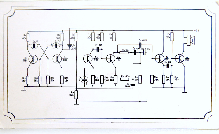
 Bild
Schaltplan einer Transistorbeschaltung
R1 4,7k C1-3 C2-3 R2 4,7k R3 330k D1 D24 L1 Л1г R10 91k R11 91k R12 1,1k R4 3,3k R5 47 R6 1k C3-0,03 C4-0,03 C5-0,015 R7 220k R8-47k L2 Л2г L3 Л3г L4 Л4г R13 100 R14 2,2k R15 100 R16 2,2k R17 12k R18 39k R19 3,9k R20 39k C6-0,025 R18 39k R21
in „Hilfe bei LTSpice nötig!“ · Analoge Elektronik und Schaltungstechnik · · Schaltpläne

-
PDF
somc-201244.pdf
E-SERIES W VOLTAV ≅MAX. ppm/°C Ω 14 16 20 0.08 1.05 1.20 1.52 01 1, 2, 5 SOMC 0.16 1.125 1.28 1.60 03 50 100 1, 2, 5 10R - 1M 24 0.08 1.05 1.20 1.52 05 1, 2, 5 1)Temperature Range: - 55 °C to + 125 °C Power rating depends on the max. temperature at the solder point, the component placement density and
-
PDF
Schaltplan.pdf
R 5 - T l a u a M c v r S T R A -2 3 5 0 D C B A T G L L 6 5 8 K K R 7 D R 1 9 9 1 1 E n E E R E 8 L s U U U U R 7 6 2 e O O H O E L R 1 2 1 2H L 6 6 6 6 6 5 7 1 f 2 2 2 2 R 7 D L o 4 1 1 1 1 L 1 5 t 4 C C C C 1 5 Q 8 h L L L L D R 7 D S : : : : D E V 6 L N N S S R 7 4 P P L L E = = = = L S S S S 3 3 4 5 5 3 K K K K 1 2 3 O J 1 2 3 O 1 2 3 4 O 0 D2 T 8 T R 7 D A A A A J C C J C 1 L1 G 1 G L L L L L S HS L S L 9 = 9 =
in „LCD Anzeige-Inhalt speichern.“ · Mikrocontroller und Digitale Elektronik ·
-
PDF
eeprom.pdf
6 1 5 14 15 16 17 18 19 20 I/2 11 14 I/4 V 12 13 I/O 1 2 S C 3 4 5 SS 3 / O/ S N / O/O / 3852 FHD F03 3852 FHD F02.1 I I V I I I 3852-1.4 3/27/96 T2/C3/D5 NS 1 Characteristics subject to change without notice X2816C PIN DESCRIPTIONS PIN NAMES Addresses (A 0A )10 Symbol Description The Address inputs
in „EEPROM mit SRAM ersetzen?“ · Mikrocontroller und Digitale Elektronik ·
-
PDF
vergleichstabelle.pdf
105 dB 0,04 dB 0,06 dB 0,10 dB 0,17 dB Litzeninnenleiter (37) für gute Flexibiliät 1 Messi&Paoloni L37 Ø 3,8 mm Ø 9,9 mm Ø 12,7 mm 2396W 1435W 907W 552W 0 6 e o Ecoflex 15 6 GHz Cu PE-F CuF+CuG 75% PVC* -55...+85 °C >90 dB 0,03 dB 0,06 dB 0,10 dB 0,16 dB Innenleiter Litze a w SSB L7 Ø 4,5 mm Ø 11,3 mm Ø 12,1 mm Ø 14,6 mm (1438W) (820W) 547W 326W K L m n Ecoflex 15 Plus 8 GHz Al vk PE-F CuF+CuG 75% PVC* -55...+85 °C >90 dB 0,03 dB 0,06 dB 0,10 dB 0,16 dB Innenleiter Litze Alu vk, geringes Gewicht 1 Ä SSB L7 Ø 4,5 mm Ø 11,3 mm Ø 12,1 mm Ø 14,6 mm
-
PDF
LPST128128A00-T4.pdf
0.15 2 (turn on) 0.15 < D ≤ 0.20 1 0.20 < D 0 2-2) Scratch on Polarizer Zone Width (W, mm) Length (L, mm) Judgment W≤0.03 Pass Pass 0.03<W≤0.05 L≤2.0 Pass A.B L>2.0 1 (turn on) 0.05<W≤0.08 L>1.0 1 L≤1.0 Pass 0.08<W (*) (*) 2-3) Polarizer Bubble Zone D size (diameter, mm) Judgment D ≤ 0.20 PASS A.B 0.20
in „Verkaufe OLED Displays FullColor 128*128 bzw. 96*64“ · Markt ·
-
PDF
Product_preview_LPST128128A00-T4__Rev_1.0_.pdf
0.15 2 (turn on) 0.15 < D ≤ 0.20 1 0.20 < D 0 2-2) Scratch on Polarizer Zone Width (W, mm) Length (L, mm) Judgment W≤0.03 Pass Pass 0.03<W≤0.05 L≤2.0 Pass A.B L>2.0 1 (turn on) 0.05<W≤0.08 L>1.0 1 L≤1.0 Pass 0.08<W (*) (*) 2-3) Polarizer Bubble Zone D size (diameter, mm) Judgment D ≤ 0.20 PASS A.B 0.20
in „O-LED Display von SMI“ · Mikrocontroller und Digitale Elektronik ·
-
PDF
IRF3205Z.pdf
– R θJA Junction-to-Ambiint ––– 62 R θJA Junction-to-Ambient (PCB Mojnt) ––– 40 www.irf.com 1 10/7/03 IRF3205ZS/L Electrical Characteristics @ T = 25°C (unless otherwise specified) J Parameter Min. Typ. Max. Units Conditions V(BR)DSS Drain-to-Source Breakdown Voltage 55 ––– ––– V VGS= 0V, D = 250µA ∆
in „Geiger Counter Sparkfun“ · Mikrocontroller und Digitale Elektronik ·
-
Datei
T6963_V1.asm
CG RAM Mode clrf Command clrf CommandData1 clrf CommandData2 movlw 0xFF movwf CommandData1 movlw 0x03 movwf CommandData2 movlw 0x42 movwf Command call writecommand2 ; Grafik Home Adresse 0x03FF clrf Command clrf CommandData1 clrf CommandData2 movlw 0x00 movwf CommandData1 movlw 0x00 movwf CommandData2
in „T6963C Versorgungspannung“ · Analoge Elektronik und Schaltungstechnik ·
-
PDF
1n5822.pdf
small. 2–1/2 x 2–1/2 copper surface. Data shown for thermal resistance junction–to–ambient (R ) θJA L L for the mountings shown is to be used as typical guideline values ÉÉ L=1/2 for preliminary engineering, or in case the tie point temperature cannot be measured. ÉÉÉÉÉÉÉ ÉÉ TYPICAL VALUES FOR R θJAIN STILL AIR ÉÉÉÉÉÉÉ ÉÉ Mounting Lead Length, L (in) Mounting Method 2 ÉÉ BOARDGROUND Method 1/8 1/4 1/2 3/4 R θJA L L ÉÉ PLANE 1 50 51 53 55 ⋅C/W ÉÉÉÉÉÉÉÉ 2 58 59 61 63 ⋅C/W VECTORPUSH–IN 3 28 ⋅C/W TERMINALST–28 4 Rectifier Device Data 1N5820 1N5821
in „Batterieschutzschaltung. Murks oder möglich?“ · Analoge Elektronik und Schaltungstechnik ·
-
PDF
Arcam-FMJ-P7.pdf
Package X100 7W005 CERAMIC RESONATOR 4.00MHz Control PCB Interface PCB Main Switch and LED Display L925CT1_1.2.SCH L925CT2_1.2.SCH L925CT3_1.2.sch DRAWING TITLE P7 Amp Controller CHANGED R200 VALUE. CORRECTED SK301 & SK302 TO 8K2402 Filename: L925CT0_1.2.Sch 02_E061 KAL 20/03/02 JP100 ADDED ON SK112
in „Bandbreite von analogen Audioschaltungen“ · Analoge Elektronik und Schaltungstechnik ·
-
PDF
Arcam-FMJ-P7.pdf
Package X100 7W005 CERAMIC RESONATOR 4.00MHz Control PCB Interface PCB Main Switch and LED Display L925CT1_1.2.SCH L925CT2_1.2.SCH L925CT3_1.2.sch DRAWING TITLE P7 Amp Controller CHANGED R200 VALUE. CORRECTED SK301 & SK302 TO 8K2402 Filename: L925CT0_1.2.Sch 02_E061 KAL 20/03/02 JP100 ADDED ON SK112
in „Bester Audio OPV“ · Analoge Elektronik und Schaltungstechnik ·
-
PDF
oki-ml380_000.pdf
2 B R b r ´ ≥ IBM: 1B 5B 54 05 00 00 00 03 F0 00 3 !! # 3 C S c s ´ EPSON: 1B 52 26 4 ¶ $ 4 D T d t ¨ 5 § % 5 E U e u ´ 6 & 6 F V f v ´ ÷ 7 ' 7 G W g w ´ ≈ 8 ( 8 H X h x ¨ ˚ 9 ) 9 I Y i y ´ • . A * : J Z j z B + ; K [ k { C — , < L \ l | n D
in „USB zu RS232“ · Mikrocontroller und Digitale Elektronik ·
-
PDF
mb1045_changed.pdf
t P0U1IN1RN 9 0 P0U1903 P03P1403 PD6 P0U170C3 C3 L7 BLM18HE601SN1D P0CN2404 9 C 5 CLK P0U1904 4 2 I2S3_SD2S30SD A8 SPKOUTRN P0U170B3 B3 L6 P0L701 BLM18HE601SN1D C P P0U1GND DOUT P0JP1402 IN2RP/VRXP SPKOUTRP P0L601 P0L602 0 P01P1401time
-
PDF
mb1045_changed_korrigiert.pdf
t P0U1IN1RN 9 0 P0U1903 P03P1403 PD6 P0U170C3 C3 L7 BLM18HE601SN1D P0CN2404 9 C 5 CLK P0U1904 4 2 I2S3_SD2S30SD A8 SPKOUTRN P0U170B3 B3 L6 P0L701 BLM18HE601SN1D C P P0U1GND DOUT P0JP1402 IN2RP/VRXP SPKOUTRP P0L601 P0L602 0 P01P1401time
-
PDF
________________KENT-128x32_ILV.pdf
0x05,0x05,0x04,0x06,0x07,0x07,0x05,0x05,0x05,0x04,0x06,0x07,0x07,0x07,0x07,0x07, 0x00,0x00,0x00,0x3C,0x3C,0x3C,0x3C,0xC0,0xC0,0xC0,0xC0,0x03,0x03,0x03,0x03,0x3C, 0x3C,0x3C,0x3C,0xFC,0xFC,0xFC,0xFC,0xFF,0xFF,0xFF,0xFF,0xFF,0xFF,0xFF,0xFF,0x00, 0x00,0x00,0x00,0xFF,0xFF,0x60,0xFE,0x9F,0x01,0x00,0xF8,0xFE,0x86,0x86,0xFE,0xF8, 0x00,0xFE,0xFE,0x06,0x06,0xFE
in „Low Power Grafik Display“ · Mikrocontroller und Digitale Elektronik ·
-
PDF
AD9952arduino.pdf
**************************************************************** 468 ;* dividiert hexH:hexL durch 10, Erg. in hexH:hexL, Rest in Temp 469 ;**************************************************************************************** 470 Div10: 471 clr Temp 472 lsl hexL 473 rol hexH 474 rol Temp ; die Division der höchstwertigsten 475 lsl hexL ; drei Bits durch 10 kann nur Null 476 rol hexH ; ergeben 477 rol Temp 478 lsl hexL 479 rol hexH 480 rol Temp 481 ldi Cnt2,13 ; Zähler für restl. 13 Bits 482 Loop10: 483 lsl hexL ; Divident um 1 nach
in „DDS-Chip mit einem AVR ansprechen“ · Mikrocontroller und Digitale Elektronik ·
-
Datei
0513.asm
__vector e_3298_put: ; 03D2 _2933__vector: ; 03D2 p_2933__trisb_flush: ; 03D2 ;; 323 : bank movfw trisb movf H'00F',w ;; 324 : tris 6 tris H'006' e_2933__trisb_flush: ; 03D4 return _2912__vector: ; 03D5 p_2912__trisa_flush: ;
in „Jal compilieren“ · Mikrocontroller und Digitale Elektronik ·
-
Datei
mcu.c
uhr_string (unsigned char *data) { ultoa(((unsigned long) uhrsekunde+((unsigned long) uhrminute*1000L)+((unsigned long) uhrstunde*1000000L)+100000000L),data,10); // 10 bedeutet Dezimal folglich 2 Binaer *(data)= LEERZEICHEN; // platzzeichen *(data+3)=':'; *(data+6)=*(data+3); } void datum_string (unsigned char *data) { ultoa(((unsigned long) uhrjahr+((unsigned long) uhrmonat*1000L)+((unsigned long) uhrtag*1000000L)+100000000L),data,10); // 10 bedeutet Dezimal folglich 2 Binaer *(data)= LEERZEICHEN; // platzzeichen *(data+3)='.'; *(data+6)=*(data+3); } void dcf77_auswerten(void
in „Tempfühler mit ATMega8535“ · Mikrocontroller und Digitale Elektronik ·
-
Datei
Lite07.asm
; lpm00 .def keymain = r01 ; aux01:key_main .def ckne555 = r02 ; aux02:clock_ne555 .def keyaux = r03 ; aux03:key_aux .def keyfbck = r04 ; aux04:key_function+bck .def swbcd01 = r05 ; aux05:switch_bcd0+1 .def swbcd23 = r06 ; aux06:switch_bcd2+3 .def aux07 = r07 ; aux07: .def aux08 = r08 ; aux08: .def
in „meinungen zu ass.prog.“ · Mikrocontroller und Digitale Elektronik ·
-
PDF
IS51BNotes.pdf
Gerät: Bus 002 Device 004. Nun die Rechte der Geräte prüfen. Hier prüfe ich die Geräte am Bus 002: ls -l /dev/bus/usb/002 tom@tom-TM6595T:~/LDaten$ ls -l /dev/bus/usb/002 crw-rw-r-- 1 root root 189, 128 Mai 11 09:04 001 crw-rw-r-- 1 root root 189, 129 Mai 11 09:04 002 crw-rw-r-- 1 root root 189, 130 Mai
-
PDF
EL2099CT.pdf
2099–11 11 EL2099C Video Distribution Amplifier D EL2099 Macromodel W A T * Connections: a input * l b input * l l a Vsupply * l l l b Vsupply * output l l l l * l l l l l .subckt M2099 4 5 1 3 2 * * Input Stage * e1 10 0 4 0 1.0 vis 10 9 0V h2 9 12 vxx 1.0 r1 5 11 50 l1 11 12 48nH iinp 4 0 5mA b iinm
in „EL2099CT als Buffer für Frequenznormal?“ · HF, Funk und Felder ·
-
Datei
usb.c
USB_PwAttributes = 0x80; // Bus-Powered, no remote wakeup __xdata BYTE USB_SerialStr[] = {0x0A, 0x03, 'f', 0, 'i', 0, 'n', 0, 'e', 0}; __xdata BYTE USB_ProductStr[] = {0x10, 0x03, 'U', 0, 'S', 0, 'B', 0, ' ', 0, 'A', 0, 'P', 0, 'I', 0}; __xdata BYTE USB_MfrStr[] = {0x1A, 0x03, 'S', 0, 'i', 0, 'l', 0, 'i', 0, 'c', 0, 'o', 0, 'n', 0, ' ', 0, 'L', 0, 'a', 0, 'b', 0, 's', 0}; BYTE SPIbuffer[4096]; BYTE pac[64]; char lastLength = 0; char txLock = 0; unsigned int count = 0; unsigned int SPIcounter = 0; unsigned int bufferSize = 4096; void main(
in „Puffer-Problem mit C8051F320 (8051)“ · Mikrocontroller und Digitale Elektronik ·