-
PDF
2243913.pdf
-bit 5.5V, W = 45 µA -0.375 ±0.25 +0.375 LSb 3.0V, I = 24 µA W (Note 7) Capacitance (P ) C — 75 — pF f =1 MHz, Code = Full-Scale A AW Capacitance (Pw) C W — 120 — pF f =1 MHz, Code = Full-Scale Capacitance (PB) C BW — 75 — pF f =1 MHz, Code = Full-Scale Note 1: Resistance is defined as the resistance
in „[V] 11St. SMD Dual Digital Poti - I2C Microchip MCP4561-103 10kOhm 256Steps Nonvolatile (8€)“ · Markt ·
-
PDF
22107B-1180063.pdf
-bit 5.5V, W = 45 µA -0.375 ±0.25 +0.375 LSb 3.0V, I = 24 µA W (Note 7) Capacitance (P ) C — 75 — pF f =1 MHz, Code = Full-Scale A AW Capacitance (Pw) C W — 120 — pF f =1 MHz, Code = Full-Scale Capacitance (PB) C BW — 75 — pF f =1 MHz, Code = Full-Scale Note 1: Resistance is defined as the resistance
in „[V] 24St SMD Digital I2C / 256 Steps 5K Dual Poti Microchip MCP4561- 502E/MS (MSOP8) (alle 15€)“ · Markt ·
-
PDF
2243913.pdf
-bit 5.5V, W = 45 µA -0.375 ±0.25 +0.375 LSb 3.0V, I = 24 µA W (Note 7) Capacitance (P ) C — 75 — pF f =1 MHz, Code = Full-Scale A AW Capacitance (Pw) C W — 120 — pF f =1 MHz, Code = Full-Scale Capacitance (PB) C BW — 75 — pF f =1 MHz, Code = Full-Scale Note 1: Resistance is defined as the resistance
in „[V] 44St. SMD Digital I2C / 256 Steps 10K Poti Microchip MCP4561- 103E/MS (MSOP8 Gehäuse)“ · Markt ·
-
PDF
2243913.pdf
-bit 5.5V, W = 45 µA -0.375 ±0.25 +0.375 LSb 3.0V, I = 24 µA W (Note 7) Capacitance (P ) C — 75 — pF f =1 MHz, Code = Full-Scale A AW Capacitance (Pw) C W — 120 — pF f =1 MHz, Code = Full-Scale Capacitance (PB) C BW — 75 — pF f =1 MHz, Code = Full-Scale Note 1: Resistance is defined as the resistance
in „[V] 10St. Digitalpoti MCP4561-103E/MS 8MSOP orginalverpackt. (9€)“ · Markt ·
-
Datei
lcd.c
,11=±£Áô (0x07 << 0); // DSS ÊýŸÝ³€¶È,0000-0010=±£Áô,0011=4λ,0111=8λ,1111=16λ SSPCR1 = (0x00 << 3) | // SOD ŽÓ»úÊä³öœûÄÜ,1=œûÖ¹,0=ÔÊÐí (0x00 << 2) | // MS Ö÷ŽÓÑ¡Ôñ,0=Ö÷»ú,1=ŽÓ»ú (0x01 << 1) | // SSE SSPʹÄÜ,1=ÔÊÐíSSPÓëÆäËüÉ豞͚ÐÅ (0x00 << 0); // LBM »ØЎģʜ //SSPCPSR = 0x02
in „Spielereien mit dem LPC-P2148“ · Mikrocontroller und Digitale Elektronik ·
-
PDF
39662c.pdf
CHARACTERISTICS Param. No. Sym Characteristic Min Max Units Conditions thCLKOUT CLKOUT Pin High Time 16.5 ns T DUTY= 50% (Note 1) tCLKOUT CLKOUT Pin Low Time 16.5 ns T DUTY= 50% (Note 1) l trLKOUT CLKOUT Pin Rise Time 3 ns Measured from 0.1 DD to 0.9 VDD, Load = 10 pF (Note 1) tfLKOUT CLKOUT Pin Fall Time 4 ns Measured from 0.9 DD to 0.1 VDD, Load = 10 pF (Note 1) Note 1: CLKOUT prescaler is set to divide by one. TABLE 16-5: REQUIREMENTS FOR EXTERNAL MAGNETICS Parameter Min Norm Max Units Conditions RX Transformer Turns Ratio 1:1 TX
in „Webserver mit XC167“ · Mikrocontroller und Digitale Elektronik ·
-
 Bild
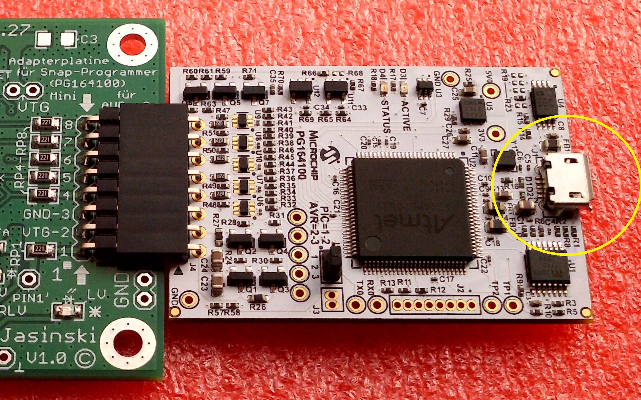
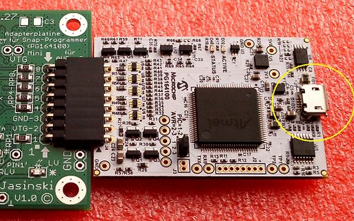
Bestückte Leiterplatte mit Atmel Mikrocontroller und USB-Anschluss
Adapterplatine für Snap-Programmer (PG164100) Mini für Atmel AVR PIC=1.2 T2.3 STATUS ACTIVE GND LV. GND U.V. Jasinski v1.0 R60 R61 R59 R74 R66 CC R68 D18 R19 R23 R43 R42 R65 R64 R67 U3 R28 R27 C26 C25 333 C8 F81 R50 R39 R48 R49 R47 R38 R37 R36 R35 R34 R33 R32 R31 R29 R24 R23 R30 R26 R57 R58 R13 R11 C17 J2 R12 R9 R3 R5 R2 C22 C21 C20 C19 C16 C15 C14 C13 C12 C11 C10 C9 C7 C6 C5 C4 C3 C2 C1
in „Entwurf USB-UART-Converter, KiCad, bitte um Review“ · Platinen · · Platinenfotos
-
PDF
ob2354ap.pdf
Minimum Standby Power Design ■ Open-frame SMPS Supplfor PC and Server ■ Audio Noise Free Operation t TY PIC AL APPLICATION 0 u ¨ v ▯ ^ 3 Output PowWr Table Product 2Open Frame 1 Open Frame 1 Notes:B2354 21W 16W 1.æMaximum practical continuous power in an open frame design with sufficient drain pattern as
in „Klackerndes Relais im CD-Player - obwohl vom Netz getrennt.“ · Analoge Elektronik und Schaltungstechnik ·
-
Datei
rtcc.h
_rtcc_flag; // _time_str and _date_str contain current time and date strings extern char _time_str[16]; // Sat 10:01:15 extern char _date_str[16]; // Sep 30, 2005 // Macroses to initiate and set RTCC #define RTCCOn() RCFGCALbits.RTCEN = 1; #define RTCCOff() RCFGCALbits.RTCEN = 0; #define RTCCLock() RCFGCALbits.RTCWREN
in „RTCC PIC24 - primary/secondary oscillator“ · Mikrocontroller und Digitale Elektronik ·
-
Datei
MAIN.C
#include <pic16f6x.h> #define __CONFIG INTIO int nSeconds = 0; // second count int nMinutes = 0; int n = 0; int nInit = 0; void main(void) { // initialize timer 0; T0CS = 0; // Timer increments on instruction clock T0IE = 1; // Enable interrupt on TMR0 overflow GIE = 1; // Global interrupt enable /*All Ports are Output*/ TRISB = 0; PORTB = 0x00; //all off PORTB = 0x01; while(1) { for(n = 0; n <= 100; ++n) { }; }; }; void
in „Ich verstehe das nicht ....“ · Mikrocontroller und Digitale Elektronik ·
-
PDF
13370-70705di.pdf
V 5V NOMINAL for comparison with the input signal’s S R2 amplitude. Upon first application of 1M input signal V IN the voltage on the C hold capacitor, C , is 0V, and V is 1 F 1 OUT 2 _ also 0V. 8 R1 + When the input signal goes more IC1 1 100k 2 ½TLC372 _ IC8 VOUT positive than the output voltage
in „Taster entprellen und erkennen funktioniert schlecht“ · Mikrocontroller und Digitale Elektronik ·
-
Datei
serout_blub.asm
; PicBasic Pro Compiler Demo, (c) 1998, 2004 microEngineering Labs, Inc. All Rights Reserved. PM_USED EQU 1 INCLUDE "16F870.INC" ; Define statements. #define CODE_SIZE 2 #define OSC 20 RAM_START EQU 00020h
in „Serielle Übertragung mit PIC 16F870“ · Mikrocontroller und Digitale Elektronik ·
-
Datei
vwcdc.c
(first packet) // 53 2C CC 33 CD 4 (first packet) // 53 2C D8 27 Seek Forward Pressed // 53 2C E0 1F Mix 6 // 53 2C E4 1B ENABLE // 53 2C F8 07 Up //#define Do_PLAY 0x08 // mix button held down (RCD300 head unit only) #define Do_PLAY 0x03 // mix button held down (RCD300 head unit only) #define Do_LOADCD
in „CD Wechsler Protokoll“ · Mikrocontroller und Digitale Elektronik ·
-
PDF
Operation_Manual_EPS-103__1_.pdf
16 memory.Sequenceofselectionisasfollows:the 1. SettheMODEswitchat„RUN”position. MODE Switch ThentheLCDdisplays„RUN”. PRG • Note TCH Memory capacity of Satellites is 32. Satellite numbers 01 ~ 16 are pre-programmed
in „[V] Steuergerät für Positionierung von Satelliten-Antenne“ · Markt ·
-
Datei
rtcc.c
time.prt11 == _time_chk.prt11)) { switch (_time.mth) { default: case 0x01: _date_str[0] = 'J'; _date_str[1] = 'a'; _date_str[2] = 'n'; break; case 0x02: _date_str[0] = 'F'; _date_str[1] = 'e'; _date_str[2] = 'b'; break; case 0x03: _date_str[0] = 'M'; _date_str[1] = 'a'; _date_str[2] = 'r'; break; case 0x04
in „RTCC PIC24 - primary/secondary oscillator“ · Mikrocontroller und Digitale Elektronik ·
-
Datei
TFT_SSD1289.c
,0x11,0x11,0x11,0x0F,0x01}, // 0x71 {0x00,0x00,0x16,0x09,0x08,0x08,0x1C,0x00}, // 0x72 {0x00,0x00,0x0E,0x10,0x0E,0x01,0x0E,0x00}, // 0x73 {0x00,0x08,0x1E,0x08,0x08,0x0A,0x04,0x00}, // 0x74 {0x00,0x00,0x12,0x12,0x12,0x16,0x0A
-
PDF
Artikel_Flashboard.PDF
A6 4 A6 RAM D3 15 AD3 k P3.4 14 T0 IC1 32 AD7 AD7 9 12 A7 A7 3 16 AD4 2 P3.5 15 P0.7 A8 25 A7 D4 17 AD5 K2 IC2.C T1 AT89S8252 A8 62256 D5 DB9 4V7 P3.6 16 WR P2.0 21 A8 A9 24 A9 D6 18 AD6 8 9 P3.7 17 22 A9 ALE 11 1 A10 21 19 AD7 1 RD P2.1
in „AT89C51AC2 ISP aber wie?“ · Mikrocontroller und Digitale Elektronik ·
-
Datei
gLCD.h
*********************************** * FileName: GenProcs.c * Dependencies: GenProcs.h * Processor: PIC18F4685 * Complier: Microchip C18 * * * Author Date Comment *~~~~~~~~~~~~~~~~~~~~~~~~~~~~~~~~~~~~~~~~~~~~~~~~~~~~~~~~~~~~~~~~~~~~ * Stephan Krause 17/8/12 Version 1.0 - Initial Release **************
in „Berechnung der Übergabeparameter beim Funktionsaufruf klappt nich immer“ · Mikrocontroller und Digitale Elektronik ·
-
Datei
main.c
******************************************************************* * * DCC Mobile Decoder Version 1.0 * ********************************************************************* * FileName: main.c * Dependencies: See INCLUDES section below * Processor: PIC16F628A * Compiler: XC8 * Company: My personal
in „DCC Lokdecoder PIC16F628“ · Mikrocontroller und Digitale Elektronik ·
-
 Bild
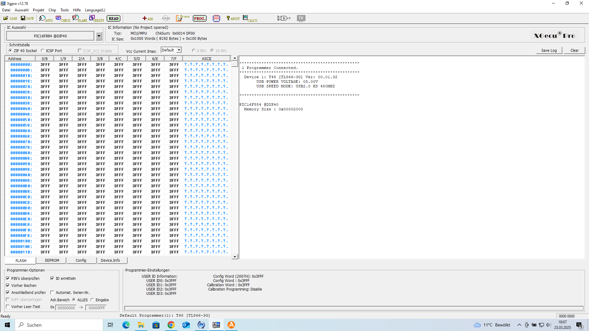
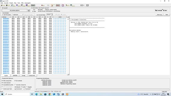
Software-Screenshot eines Mikrocontroller-Programmierers
Xgecu Pro PIC16F84 Programmer Connected. Device: 1 USB VOLTAGE: 5.00V USB SPEED MODE: USB 2.0 480MHz Memory Size: 0x00002000 FLASH EEPROM Config Device.info
in „EEPROM auslesen“ · Mikrocontroller und Digitale Elektronik · · Screenshots
-
 Bild
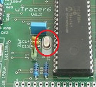
Nahaufnahme einer Leiterplatte mit Mikrocontroller und Quarz
uTracer6 V6.2 C63 R69 C14 30pf C13 L61 150uH L60 150uH J1 PIC16F884 MICROCHIP
in „Quarze gesucht“ · Mikrocontroller und Digitale Elektronik · · Platinenfotos
-
 Bild
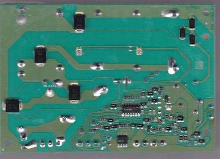
Rückseite einer Leiterplatte mit Lötstellen
BT145-800R, PIC16F3503, 6DW, W17, SP, LF, 29W, 6DW, 6DW, 6DW, 5DW, A4W, A7W, X1FA, 29W, BF9358
in „AKO Weidezaungerät reparieren“ · Analoge Elektronik und Schaltungstechnik · · Platinenfotos
-
Datei
main_FFTExample.c
FileName: main_FFTExample.c * Dependencies: Header (.h) files if applicable, see below * Processor: dsPIC30Fxxxx * Compiler: MPLAB® C30 v3.00 or higher * IDE: MPLAB® IDE v7.52 or later * Dev. Board Used: dsPICDEM 1.1 Development Board * Hardware Dependencies: None * * SOFTWARE LICENSE AGREEMENT: * Microchip
in „FFT mit dsPIC“ · Digitale Signalverarbeitung / DSP / Machine Learning ·
-
PDF
24LC32A.pdf
capacitance — — 10 pF VCC = 5.0V (Note 1) COUT (all inputs/outputs) TA= 25°C, CLK= 1 MHz D9 ICCwrite Operating current — 0.1 3 mA VCC = 5.5V, SCL = 400 kHz D10 ICCread — 0.05 1 mA — D11 ICCS Standby current — 0.01 1 µA Industrial
in „I2C Eeprom: Buskollisionen nach einem schnellen Reset“ · Mikrocontroller und Digitale Elektronik ·
-
 Bild
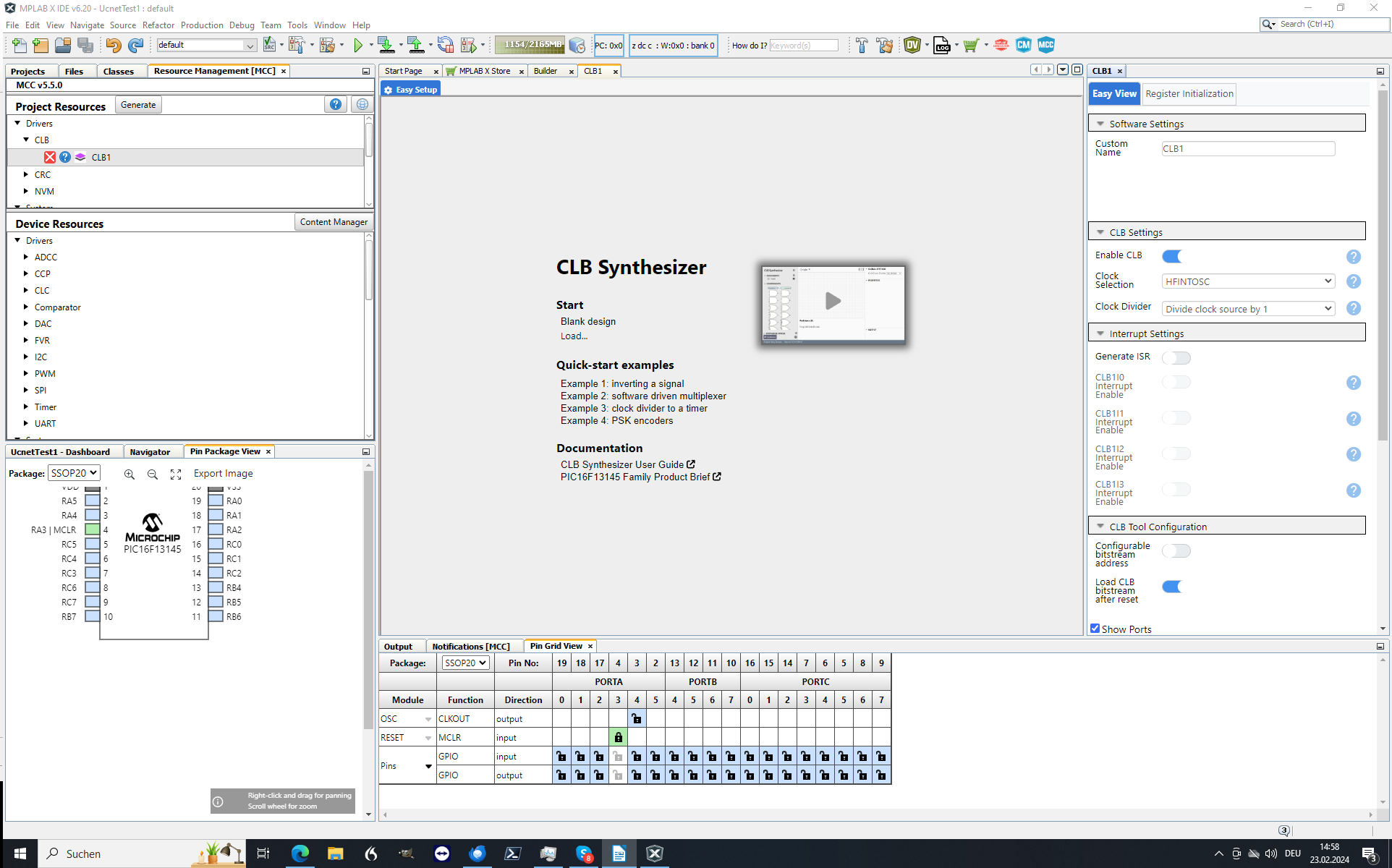
Screenshot der MPLAB X IDE Software
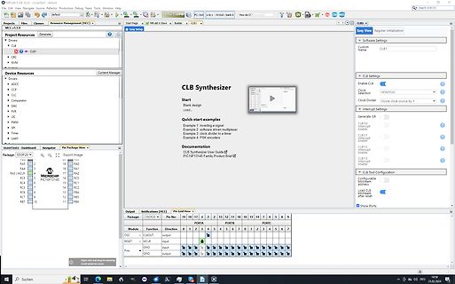
MPLAB X IDE v5.35 - Project: Unset - default Project Resources Drivers CLB1 Device Resources ADCC CCP CLUC Comparator DAC FVR AC PWM SPI Timer UART CLB Synthesizer Documentation CLB Synthesizer User Guide PIC16F13145 Family Product Brief Software Settings CLB Settings CLB Tool
in „Microchip CLB – erste Versuche zur „FPGA-Zelle“ im Achtbitter“ · Mikrocontroller und Digitale Elektronik · · Screenshots
-
Datei
SinusoidalBLDC_v1.2.c
controller. Position form implementation of // a digital PID. See SpeedControl subroutine for details SFRAC16 Kp = SFloat_To_SFrac16(0.1); // P Gain SFRAC16 Ki = SFloat_To_SFrac16(0.01); // I Gain SFRAC16 Kd = SFloat_To_SFrac16(0.000); // D Gain // Constants used by the PID controller, since a MAC operation
in „Probleme beim Importieren von Projekten nach Linux MPLAB_X mit MPLAB®XC16 Compiler“ · Mikrocontroller und Digitale Elektronik ·
-
Datei
PIC_test.c
#include <PIC16F877.h> void pause() { OPTION = 3; TMR0 = 99; while (TMR0); } void main() { TRISB = 0b.1111.1110; bit out @ PORTB.0; for(;;) { out = 1; for(char i = 0; i < 1000; i++) { pause(); } out = 0; for(char
in „PIC16F877 geht nicht!“ · Mikrocontroller und Digitale Elektronik ·
-
 Bild
Software-Screenshot eines PIC-Programmierers
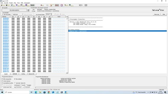
Xgecu V2.7 READ PIC16F54 @ DIP40 IC Information (No Project loaded) Type: MCU/MPU ChSum: 0x0000 FF00 IC Size: 0x1000 Words (8192 Bytes) @ 0x100 Bytes Device: 1 T48 [TL666-3G] Ver: 00.01.32 USB VOLTAGE: 5.0V USB SPEED MODE
in „EEPROM auslesen“ · Mikrocontroller und Digitale Elektronik · · Screenshots
-
PDF
Sensorless_Speed_Controlled_BLDC.pdf
-Based Sensorless BLDC Drive +18V D1 F1 NTC1 10TQ045 R1 2A R2 +15V 560R 220R 0.5W R3 D2 C1 120R 1.5W 15V 100nF V1 +C2 2200uF Vdc C3 + U1 220uF LM7805A R4 1 3 +5V 220R 2 GND C4 C5 100nF 100nF TX1 +5V R6 +5V C6 +5V R5 1K R7 100nF 330R 10K
in „sensorloser BLDC Motor mit PWM“ · Mikrocontroller und Digitale Elektronik ·
-
PDF
an1003.pdf
3.3 k AC AC - 100 Input Load VoltageCurrent R2 CR 1 SCR 1 R3 Q4006LH4 MT2 250 k 115 V ac 120 V ac 0.8 A 500 k IN4003 EC103B 1 k Input 15 k 1/2 W G MT1 60 Hz Not HT-32 0.1 µF 120 V ac 8.5 A 100 k IN4003 S2010F1 Required 400 V 60 Hz 0.1 µF 0.1 µF 1 k 400 V 100 V 240 V ac 0.8 A 1 M IN4004 EC103D 60 Hz Not Figure AN1003.16 Circuit for Phase Controlling a Permanent Magnet 240 V ac 8.5 A 250 k IN4004 S4010F1 Required Motor 60 Hz 1 k PM motors normally require full-wave DC rectification
in „hysteresefreie Phasenanschnittsteuerung“ · Analoge Elektronik und Schaltungstechnik ·
-
Datei
pic16f877a.h
OUT OF THE USE OF * THIS SOFTWARE, EVEN IF ADVISED OF THE POSSIBILITY OF SUCH DAMAGE. */ #ifndef _PIC16F877A_H_ #define _PIC16F877A_H_ /* * C Header file for the Microchip PIC Microcontroller * PIC16F877A */ #ifndef __XC8 #warning Header file pic16f877a.h included directly. Use #include <xc.h> instead
in „HEX-Datei erstellen“ · Mikrocontroller und Digitale Elektronik ·
-
PDF
Thyristor_Triac_App_Note__by_Littlefuse.pdf
subject to change without notice. Revised: 09/23/13 ® Teccor brandThyristors AN1003 Load Load Quadrac R 1 250k (Q4010LT) R 4 3.3 k Quadrac 100 (Q4010LT) R2 68 k R 2 3.3k R1 250 k 120V 120 V R 3 (60Hz) (ForInductive (60 Hz) Loads) 100 k Trim C1 Diac 0.1µF C 2 C1 Diac 0.1µF 0.1 µF 0.1 µF Figure AN1003.9 Basic
in „Ansteuerschaltung Thyristor und Triac“ · Analoge Elektronik und Schaltungstechnik ·
-
PDF
Littelfuse_App_Note_AN1003.pdf
subject to change without notice. Revised: 09/23/13 ® Teccor brandThyristors AN1003 Load Load Quadrac R 1 250k (Q4010LT) R 4 3.3 k Quadrac 100 (Q4010LT) R2 68 k R 2 3.3k R1 250 k 120V 120 V R 3 (60Hz) (ForInductive (60 Hz) Loads) 100 k Trim C1 Diac 0.1µF C 2 C1 Diac 0.1µF 0.1 µF 0.1 µF Figure AN1003.9 Basic
in „Phasenanschnittsteuerung“ · Analoge Elektronik und Schaltungstechnik ·
-
Datei
0513.asm
0.4.60 ; date : 24-Jul-2012 19:43:27 ; main source : 0513 ; command line : 0513.jal ; target chip : 16f84 ; cpu : pic 14 ; clock : 4000000 ; input files : 19 ; lines : 3196 ; chars : 80661 ; compilation nodes : 20669 ; stack : 51Kb ; heap : 6123Kb ; seconds : 0.340 (9400 lines/second) ; output code :
in „Jal compilieren“ · Mikrocontroller und Digitale Elektronik ·
-
Datei
display.c
const uint8_t schriftDrehz[] = {ESC, Z, F, _1_, _1_, KOMMA, LF}; // Schriftart - #ZF ARIAL_44 const uint8_t schriftEinh[] = {ESC, Z, F, _5_, KOMMA, LF}; // Schriftart - #ZF CHICAGO14 const uint8_t einh[] = {ESC, Z, R, _4_, _4_, _0_, KOMMA, _
in „Pointer suche“ · Mikrocontroller und Digitale Elektronik ·
-
Datei
mca25.c
(mca25_buf); if (memcmp_P(mca25_buf,PSTR("AT+CMUX=0,0,7,31"),16)) return 4; USART_pstr_P(PSTR("\r\r\nOK\r\n")); mca25_read_mux_packet(mca25_buf); if (memcmp_P(mca25_buf,PSTR("\xF9\x03\x3F\x01\x1C\xF9"),6)) return 5; USART_pstr_P(PSTR("\xF9\x03\x73\x01\xD7\xF9"));
in „AVR für wenig Geld im LAN“ · Mikrocontroller und Digitale Elektronik ·
-
 Bild
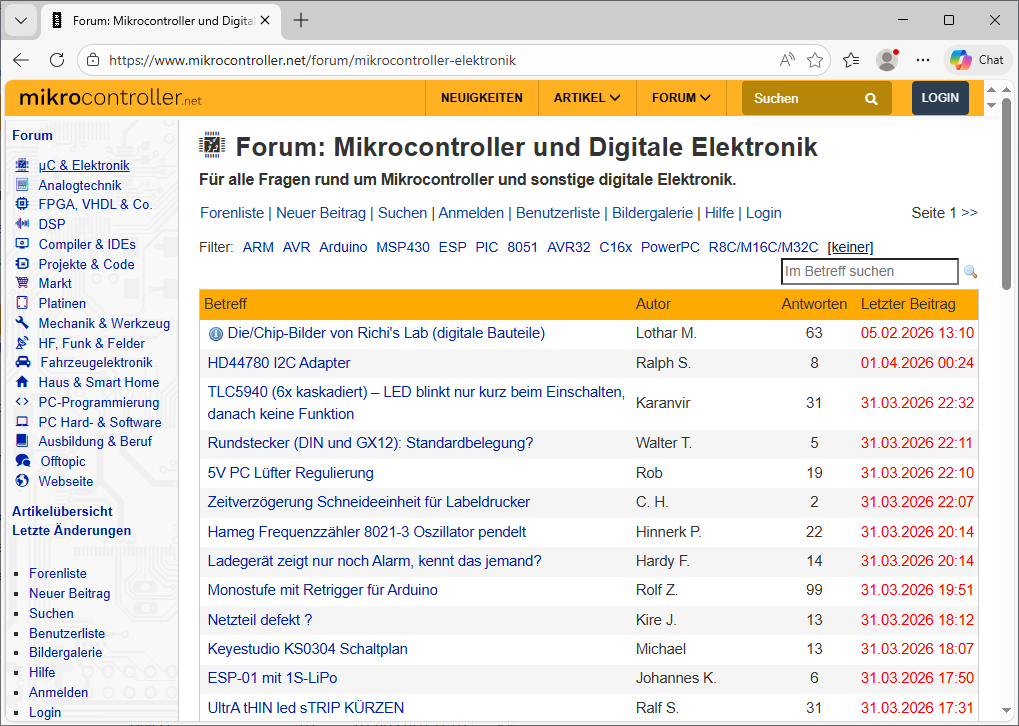
Screenshot eines deutschsprachigen Elektronik-Forums
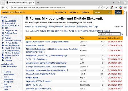
Suchen | Anmelden | Benutzerliste | Bildergalerie | Hilfe | Login Filter: ARM AVR Arduino MSP430 ESP PIC 8051 AVR32 PowerPC R8/M16/M32C [keiner] Betreff | Autor | Antworten | Letzter Beitrag Die/Chip-Builder von Richi's Lab (digitale Bauteile) | Lothar M. | 63 | 05.02.2026 13:10 HD44780 I2C Adapter | Ralph
in „Seltsamer Link zu embdev.net“ · www.mikrocontroller.net · · Screenshots
-
Datei
neu-0513.asm
date : 25-Jul-2012 18:33:49 ; main source : neu-0513 ; command line : neu-0513.jal ; target chip : 16f84 ; cpu : pic 14 ; clock : 4000000 ; input files : 19 ; lines : 3196 ; chars : 80660 ; compilation nodes : 20642 ; stack : 51Kb ; heap : 6116Kb ; seconds : 0.350 (9131 lines/second) ; output code :
in „Jal compilieren“ · Mikrocontroller und Digitale Elektronik ·
-
Datei
datei-dmesg.txt
[ 0.105160] pci 0000:00:1f.1: [8086:24ca] type 00 class 0x01018a [ 0.105178] pci 0000:00:1f.1: reg 0x10: [io 0x0000-0x0007] [ 0.105191] pci 0000:00:1f.1: reg 0x14: [io 0x0000-0x0003] [ 0.105203] pci 0000:00:1f.1: reg 0x18: [io 0x0000-0x0007] [ 0.105216] pci 0000:00:1f.1: reg 0x1c: [io 0x0000-0x0003] [ 0.105228] pci 0000:00:1f.1: reg 0x20: [io 0x1860-0x186f] [ 0.105241] pci 0000:00:1f.1: reg 0x24: [mem 0x00000000-0x000003ff] [ 0.105354] pci 0000:00:1f.3: [8086:24c3
in „Limux:: Netzwerk und WLAN futsch.“ · PC Hard- und Software ·
-
Datei
USART_PC.txt
#include <p18f252.h> #include <stdlib.h> #include <delays.h> #include <usart.h> #pragma config OSC = HSPLL //16MHz #pragma config WDT = OFF, PWRT = ON #pragma config LVP = OFF // must be OFF for HSKA Pic eval board
in „RS232 programmierung unter C18“ · Mikrocontroller und Digitale Elektronik ·
-
 Bild
Screenshot der PICkit2 Programmier-Software
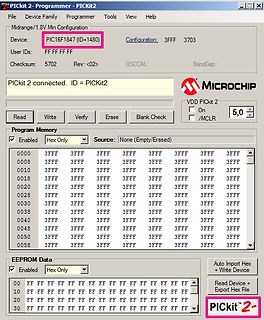
PICkit2- Programmer- PICKit2 File Device Family Programmer Tools View Help Midrange/1.8V Min Configuration Device: PIC16F1847 (ID=1480) Configuration: 3FFF 3703 User IDs: FF FF FF Rev: <02> Checksum: 5702 OSCCAL: BandGap PICKit 2 connected. ID = PICkit2 MICROCHIP VDD PICKit 2 On 5,0 /
in „PIC16LF1847 flashen mit ATmega / USBasp / Arduino Nano / ponyser?“ · Mikrocontroller und Digitale Elektronik · · Screenshots
-
Datei
ds1820.h
°C resolution */ temp_u16 >>= 1; /* temperature resolution is TEMP_RES (0x100), so 1°C equals 0x100 */ /* => convert to temperature to 1/256°C resolution */ temp_u16 = ((uint16)temp_u16 << 8); /* now substract 0.25°C */ temp_u16
-
PDF
ARM_Procedure_Call_Standard_for_the_ARM_Architecture_V2.1.pdf
) 16 5.2 Processes, Memory and the Stack 16 5.2.1 The Stack 16 5.2.1.1 Universal stack constraints 17 5.2.1.2 Stack constraints at a public interface 17 ARM IHI 0042F Copyright © 2003-2009, 2012, 2014-2015
in „C und C++ kompatibilität“ · Mikrocontroller und Digitale Elektronik ·
-
Datei
Petra-M10_Einblick_offen.html
kpbb{background-color:#4d90fe;background-image:-webkit-linear-gradient(top,#4d90fe,#4787ed);border:1px solid #3079ed}.kpgrb{background-color:#f5f5f5;background-image:-webkit-linear-gradient(top,#f5f5f5,#f1f1f1);border:1px solid #dcdcdc;color:#555}.ksb{background-color:#f8f8f8;background-image:-webkit-linear-gradient
in „Lampentaster gesucht“ · Markt ·
-
Datei
NHD_2_7.ino
0x18, 0xC0, 0x7B, 0x00, 0x00, 0x00, 0x00, 0x7C, 0x7F, 0xDD, 0x8E, 0xE3, 0x7B, 0x1F, 0xC3, 0x61, 0xB8, 0xFC, 0x7B, 0x00, 0x00, 0x00, 0x00, 0x00, 0xFF, 0xDF, 0x8F, 0xC1, 0xDF, 0x1F, 0xC6, 0x61, 0xB1, 0xFC, 0x6F, 0x00, 0x00, 0x00, 0x3C, 0x01, 0xC0, 0x1B,
in „NHD-2.7-12864WDW3 mit SSD1322 - Grayscale Problem“ · Mikrocontroller und Digitale Elektronik ·
-
PDF
LT3757_Boost-Sepic-Flyback-Invert.pdf
TA05d 3757 TA05e 2ms/DIV 50μs/DIV 3757f 31 LT3757 TYPICAL APPLICATIONS 5V to 12V Input, ±12V/0.2A Output SEPIC Converter V IN 5V TO 12V + CIN2 CIN1 105k • CDC1 47μF 1μF VIN T1 4.7μF 16V 16V,X5R 1,2,3,416V, X5R SHDN/UVLO D1 VOUT1 46.4k 12V LT3757 1.05k 0.4A SYNC GATE M1 CDC2 COUT2 4.7μF 1% 4.7μF 16V 5 16V, X5R SENSE X5R • 158Ω s▯3 1% RT FBX 0.02Ω GND SS D2 COUT2 4.7μF VC GND INTV CC 6 16V, X5R s▯3 VOUT2 30.9k • –12V 400kHz 22k 0.4A CVCC 3757 TA06
in „Datenblätter von Linear Technologies“ · Analoge Elektronik und Schaltungstechnik ·
-
PDF
KSZ8851SNL.pdf
0x15 0x14 MARH — MAC Address Register High [7:0] 0x14 0x15 MAC Address Register High [15:8] to 0x17 0x16 - 0x17 0x16 Reserved Don’t Care None 0x17 0x18 0x18 0x18 - 0x19 0x19 to Reserved Don’t Care None 0x1B 0x1A 0x1A - 0x1B 0x1B 0x1C 0x1C - 0x1D 0x1C 0x1D to 0x1E Reserved Don’t Care None 0x1F 0x1E - 0x1F
in „KSZ8851 Ethernet komplizierte Frage.“ · Mikrocontroller und Digitale Elektronik ·
-
Datei
source.bas
) THEN ' E e C0 = $7F ' C1 = $49 ' C2 = $49 ' C3 = $49 ' C4 = $41 ' wchar = 1 ' ENDIF ' W2 = W2 + 1 ' if (W0 = W2) THEN ' F f C0 = $7F ' C1 = $48 ' C2 = $48 ' C3 = $48 ' C4 = $40 ' wchar = 1 ' ENDIF ' W2 = W2 + 1 ' if (W0
in „.bas übersetzten in Picbasic Pro?“ · Mikrocontroller und Digitale Elektronik ·
-
PDF
s_p305_intel_mm_pro_p300.pdf
P300 and Satellite Pro P300 Maintenance Manual(960-Q08) 31 Appendix. D Appendix D Display Codes D.1 Display Codes Table D-1 Scan codes (set 1 and set 2) (1/4) Cap Code set 1 Code set 2 No. Keytop Make Break Make Break Note 01 ‘ ~ 29 A9 0E F0 0E 02 1 ! 02 82 16 F0 16 03 2 @ 03 83 1E F0 1E 04 3 # 04
in „LCD-Inverter kaputt - wer kann helfen?“ · PC Hard- und Software ·
-
Datei
1_dht11.c
/* Project: Temperature and humidity measurements using DHT11 MCU: PIC16F628A Clock: 4.0MHz external resonator MCLR is enabled Date: Jan 10, 2012 Written by: Rajendra Bhatt (www.embedded-lab.com) */ // LCD module connections sbit LCD_RS at RB4_bit; sbit LCD_EN at RA4_bit
in „Feuchtigkeitsmessung DHT11 PIC16F690 - Hilfe C-Cde gesucht-“ · Mikrocontroller und Digitale Elektronik ·