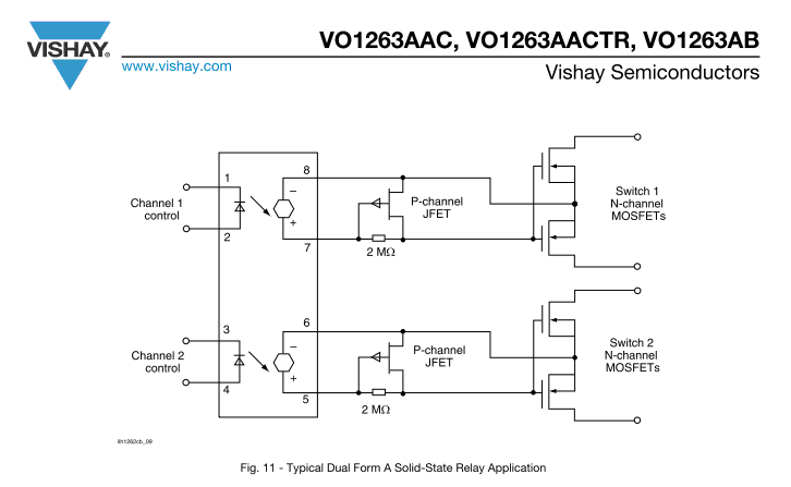
sinusoidal reference to the current loop. 4 CS Input to the PWM comparator. The current flowing in the MOSFET is sensed through a resistor, the resulting voltage is applied to this pin and compared with an internal sinusoidal-shaped reference, generated by the multiplier, to determine MOSFET’s turn-off. 5
MOTOROLA SEMICONDUCTOR TECHNICAL DATA The RF MOSFET Line MRF275L RF Power Field-Effect Transistor N–Channel Enhancement–Mode 100 W, 28 V, 500 MHz Designed for broadband commercial and military applications using single N–CHANNEL ended circuits at frequencies
the PFC converter again works at half the rated frequency to reduce current consumption. While the MOSFET Q1is switching, a modulated AC voltage appears at the secondary windings of choke L2. The voltage across the main winding of choke L2 varies during rated operation from 400V when Q1 is cut off and
PD - 9.1244C IRF7401 HEXFET Power MOSFET Q Generation V Technology A Q Ultra Low On-Resistance S 1 8 DA V DSS = 20V Q N-Channel Mosfet S 2 7 D Q Surface Mount S 3 6 D Q Available in Tape & Reel G 4 5 D Q Dynamic dv/dt Rating R DS(on) = 0.022Ω
PD-93853C IRF1404S IRF1404L HEXFET Power MOSFET l Advanced Process Technology D l Ultra Low On-Resistance V = 40V l Dynamic dv/dt Rating DSS l 175°C Operating Temperature l Fast Switching R DS(on) = 0.004 G l Fully Avalanche Rated I = 162A Seventh Generation HEXFET Power MOSFETs from S D International Rectifier utilize advanced processing techniques to achieve extremely low on-resistance per silicon area. This benefit, combined with the fast switching speed and ruggedized
PD -91896E IRF1404 HEXFET Power MOSFET l Advanced Process Technology D l Ultra Low On-Resistance V DSS = 40V l Dynamic dv/dt Rating l 175°C Operating Temperature l Fast Switching R DS(on) = 0.004 G l Fully Avalanche Rated ID= 162A Description S ® Seventh Generation HEXFET Power MOSFETs from International Rectifier utilize advanced processing techniques to achieve extremely low on-resistance per silicon area. This benefit, combined with the fast switching speed and ruggedized device
system circuit will monitor the current with the MOSFET detection circuit triggering to provide an effective barrier behind which sensitive electronics will not be exposed to large voltages or currents during surge events. The TBU device is provided in
power MOSFET. 14 ALS A Low-side Source connection. Connect to source of A Low-side power MOSFET. 15 VCC Positive supply to gate drivers. Must be same potenDDa(Pin 16). Connect to anodes of two bootstrap diodes.
DATA Monolithic temperature and SYMBOL PARAMETER MAX. UNIT overload protected logic level power MOSFET in a 3 pin plastic VDS Continuous drain source voltage 50 V envelope, intended as a general D Continuous drain current 13.5 A purpose switch for automotive PD Total power dissipation 40 W systems and
Synchronized Switch Regulator IP6518 is a synchronized switch buck regulator Built-in power MOSFET and support 13 fast charge output standards, support Input voltage range: 10.5V~32V Output voltage range: 3V~20V, adjust along Type-C and PD output, providing solutions for car with fast charge
Bauteiltester >FA-BT2< universellen Bauteiltester für bipolare Transistoren, MOSFETs, JFETs, Dioden, Triacs, Thyristoren, Widerstände, Spulen und Kondensatoren inklusive ESR-Messung Bauanleitung Bauanleitung für den Bauteiltester ›FA-BT2‹ FA-LESERSERVICE Mess- und Prüfgeräte für elektronsiche
TK6A60W MOSFETs Silicon N-Channel MOS (DTMOS) TK6A60W 1. Applications • Switching Voltage Regulators 2. Features (1) Low drain-source on-resistance: R DS(ON) = 0.68 Ω (typ.) by used to Super Junction Structure :
TK6A60W MOSFETs Silicon N-Channel MOS (DTMOS) TK6A60W 1. Applications • Switching Voltage Regulators 2. Features (1) Low drain-source on-resistance: R DS(ON) = 0.68 Ω (typ.) by used to Super Junction Structure :
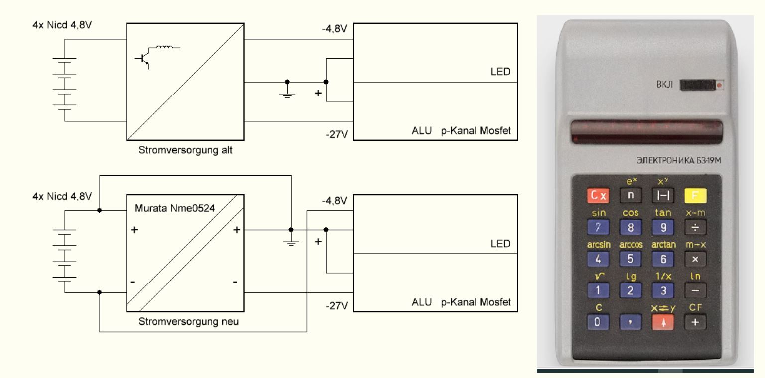
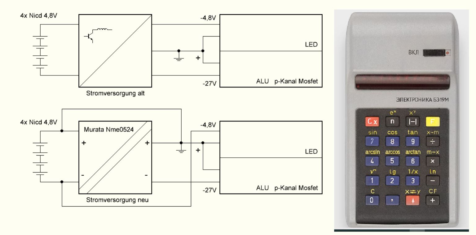
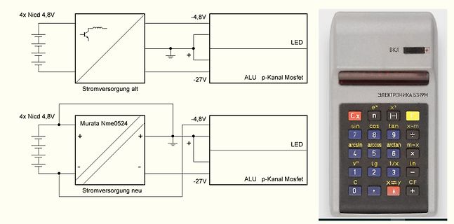
4x Nicd 4,8V Stromversorgung alt -4,8V LED -27V ALU p-Kanal Mosfet Murata Nme0524 Stromversorgung neu -4,8V LED -27V ALU p-Kanal Mosfet ЭЛЕКТРОНИКА Б3-19
Reset (POR) circuits continually monitor the decouple between the drain terminal of the high side MOSFET bias voltages (PVCC and VCC) and the voltage at the EN pin. The and the source terminal of the low side MOSFET. This is used to POR function initiates soft-start operation 384 clock cycles after reduce
4x Nicd 4,8V Stromversorgung alt -4,8V LED -27V ALU p-Kanal Mosfet Murata Nme0524 Stromversorgung neu 4x Nicd 4,8V -4,8V LED -27V ALU p-Kanal Mosfet ЭЛЕКТРОНИКА Б3-19м
damit dort u werden (Gate Driver schützen).
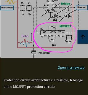
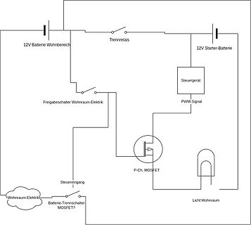
Auf dem Bild im Anhang sind drei Optionen für IGBT und MOSFETs. Bei dem MOSFET versteh ich den Schutz mit bei den anderen Varianten wäre ich für jeden Rat dankba
Grüße Andre
Si9435BDY New Product Vishay Siliconix P-Channel 30-V (D-S) MOSFET PRODUCT SUMMARY FEATURES D TrenchFETr Power MOSFET V DS (V) rDS(on) (W) D (A) 0.042 @ VGS = −10 V −5.7 −30 0.055 @ VGS= −6 V −5.0 0.070 @ VGS = −4.5 V −4.4 S SO-8 S D 1 8 G S D 2 7 S D 3 6 G 4 5 D Top View D Ordering Information: Si9435BDY Si9435BDY-T1 (with Tape and Reel) P-Channel MOSFET ABSOLUTE MAXIMUM RATINGS (T = 25_C UNLESS OTHERWISE NOTED) A Parameter Symbol 10 secs Steady State Unit Drain-Source Voltage VDS −30 V Gate-Source Voltage VGS "20 T = 25_C −5.7 −4.1 Continuous Drain
Drehgeschwindigkeit des Motorankers. Als steuerbare Ventile in H-Brücken verwendet man in der Praxis sogenannte MOSFET-Transistoren. Ebenso existiert eine Menge speziell entwickelter Treiber-Schaltkreisen, die sowohl ganze H-Brücke, als auch einen Teil Steuer- und Hilfselektronik beinhalten. Ein solcher Treiber in
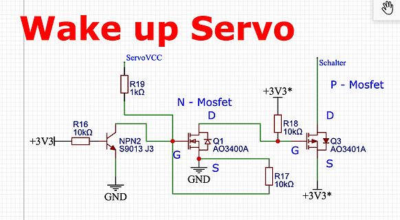
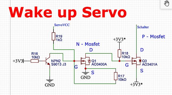
Wake up Servo
ServoVCC
R19 1k
+3V3*
R18 10k
Schalter
P - Mosfet
D
+3V3*
N - Mosfet
D
Q1 AO3400A
G
S
Q3 AO3401A
G
S
R17 10k
+3V3*
R16 10k
+3V3
NPN2 S9013 J3
GND
wesentlichen besteht die Schaltung aus dem kleinen Mikrocontroller ATTiny26 von Atmel, zwei Power-MOSFETs, einem 470 uF Elko und einer 100 uH Spule. Die Strom- regelung sowie das Ladeverfahren sind per Software realisiert. Im Schnelllade-Modus wird mit dem eingestellten Strom geladen. Um zuverlässig den
been downloaded from http://www.datasheetarchive.com. PD- 91363E IRLR024N IRLU024N HEXFET Power MOSFET l Logic-Level Gate Drive D l Surface Mount (IRLR024N) V DSS = 55V l Straight Lead (IRLU024N) l Advanced Process Technology R DS(on) = 0.065 l Fast Switching G l Fully Avalanche Rated ID= 17A S Description Fifth Generation HEXFET ® Power MOSFETs from International Rectifier utilize advanced processing techniques to achieve the lowest possible on- resistance per silicon area. This benefit, combined with the fast switching speedandruggedizeddevicedesignthatHEXFETpowerMOSFETsarewell
been downloaded from http://www.datasheetarchive.com. PD- 91363E IRLR024N IRLU024N HEXFET Power MOSFET l Logic-Level Gate Drive D l Surface Mount (IRLR024N) V DSS = 55V l Straight Lead (IRLU024N) l Advanced Process Technology R DS(on) = 0.065 l Fast Switching G l Fully Avalanche Rated ID= 17A S Description Fifth Generation HEXFET ® Power MOSFETs from International Rectifier utilize advanced processing techniques to achieve the lowest possible on- resistance per silicon area. This benefit, combined with the fast switching speedandruggedizeddevicedesignthatHEXFETpowerMOSFETsarewell
PD-91896F IRF1404 ® HEXFET Power MOSFET l Advanced Process Technology l Ultra Low On-Resistance D l Dynamic dv/dt Rating VDSS = 40V l 175°C Operating Temperature l Fast Switching R = 0.004Ω l Fully Avalanche Rated G DS(on) l Automotive Qualified (Q101) ID = 202A Description S Seventh Generation HEXFET Power MOSFETs from International Rectifier utilize advanced processing techniques to achieve extremely low on-resistance per silicon area. This benefit, combined with the fast switching speed and ruggedized device
’s inverting input is held at vir- tual ground potential, so whenever fewcomponents IC 1s output MOSFET turns on, the Anthony H Smith, Scitech, Bedfordshire, England voltageacrossR 1 approximatelyequals the negative-supply-rail voltage, ⫺V . S Requiring no rectifier diodes, As a consequence, the charge
PD-94184D IRL3713 SMPS MOSFET IRL3713S IRL3713L Applications l High Frequency Isolated DC-DC HEXFET Power MOSFET Converters with Synchronous Rectification for Telecom and Industrial Use V DSS R DS(on) max (mW) ID 30V 3.0@V = 10V
IRLML6402PbF ® l Ultra Low On-Resistance HEXFET Power MOSFET l P-Channel MOSFET l SOT-23 Footprint G 1 l Low Profile (<1.1mm) l Available in Tape and Reel V DSS = -20V 3 D l Fast Switching l Lead-Free R = 0.065Ω S 2 DS(on) l RoHS Compliant, Halogen-Free Description These P-Channel MOSFETs from International Rectifier utilize advanced processingtechniquestoachieveextremelylow on-resistancepersilicon area. Thisbenefit,combinedwiththefastswitchingspeedandruggedized devicedesignthatHEXFET
Si4946BEY Vishay Siliconix Dual N-Channel 60-V (D-S) 175 °C MOSFET PRODUCT SUMMARY FEATURES VDS (V) R DS(on)(Ω) ID(A) Qg(Typ.) • Halogen-free According to IEC 61249-2-21 Definition 0.041 at VGS = 10 V 6.5 ® 60 9.2 nC TrenchFET Power MOSFET 0.052 at VGS= 4.5 V 5.8
FastIRFET™ IRFH4210DPbF ® HEXFET Power MOSFET V DSS 25 V R DS(on)ax 1.10 (@ V GS= 10V) m (@ V = 4.5V) 1.35 GS Qg (typical) 37.0 nC D (@T = 25°C) 100 A PQFN 5X6 mm C (Bottom) Applications Synchronous Rectifier MOSFET for Synchronous Buck
wesentlichen besteht die Schaltung aus dem kleinen Mikrocontroller ATTiny26 von Atmel, zwei Power-MOSFETs, einem 470 uF Elko und einer 100 uH Spule. Die Strom- regelung sowie das Ladeverfahren sind per Software realisiert. Im Schnelllade-Modus wird mit dem eingestellten Strom geladen. Um zuverlässig den
IRFHS8342PbF HEXFET Power MOSFET V 30 V TOP VIEW DS V GS max ± 20 V D R DS(on) max D 1 6 D D 16.0 mΩ D G (@V GS = 10V) D 2 D 5 D Q g(typical) 4.2 nC D (@V = 4.5V) D S GS G 3 S 4 S S I D 8.5 d A 2mm x 2mm PQFN (@T c(Bottom) 25°C) Applications • Control MOSFET for Buck Converters • System/Load Switch FeaturesandBenefits Features Resulting Benefits Low RDSon(≤ 16.0mΩ) Lower Conduction Losses Low Thermal Resistance to PCB (≤/W) Enable better thermal dissipation
-1165 Franzis' Das große Werkbuch Elektronik Band 2 Dioden Thyristoren Triacs Transistoren FETs, MOSFETs Power-MOSFETs Operationsverstärkertechnik Optoelektronik Sensoren Röhrentechnik LWL-Technik Stromversorgung Seiten 1156-2215 Franzis' Das große Werkbuch Elektronik Band 3 Transistor-Schaltungen Operationsverstärkerschaltungen
To improve the reliability of the MOSFET and hence the power supply, the designer could choose to increase the thermal derating of the part. By significantly cooling the part down and setting the working temperature of the MOSFET at 80°C
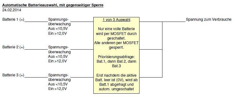
(+)
Spannungsüberwachung
Aus <10,5V
Ein >12,0V
1 von 3 Auswahl
Nur eine volle Batterie wird per MOSFET durchgeschaltet. Alle anderen per MOSFET gesperrt.
Priorisierungsabfrage: Bat.1, dann Bat.2, dann Bat.3
Erst nachdem die aktive Batt. leer ist (0V), wird ab Batt.1 abgefragt und autom. umgeschaltet
Input/Output Leakage -35V 45mΩ @ V GS = -10V -12A • Complementary Pair MOSFET • Lead Free/RoHS Compliant (Note 1) • "Green" Device (Note 2) Description and Applications • Qualified to AEC-Q101 Standards for High Reliability This new generation MOSFET has been designed to minimize
IPA50R190CE MOSFET 500V CoolMOSª CE Power Transistor PG-TO 220 FP CoolMOS™ is a revolutionary technology for high voltage power MOSFETs, designed according to the superjunction (SJ) principle and pioneered by Infineon

 Bild
 Bild
 Bild
 Bild

 Bild
 Bild
 Bild

 Bild
 Bild
 Bild
 Bild
 Bild

 Bild

 Bild
 Bild
 Bild