-
Datei
main.c
#include <stm32f1xx.h> //Core Header for STM32F103C8T6 Processor #include <stdio.h> #define EEPROM_DEVICE 0xA0 //All Addresspins grounded #define EEPROM_WRITE 0 #define EEPROM_READ 1 int main(void) { //Enable Clocks
in „STM32 I2C EEPROM lässt sich lesen aber nicht beschreiben“ · Mikrocontroller und Digitale Elektronik ·
-
Datei
main.c
-----------------------------------------------------------*/ #define SYSCLK_FREQ_48MHz #include "stm32f10x_conf.h" #include "system_stm32f10x.h" /* Standard Includes */ #include <stdbool.h> #include <stdint.h> #include <stdio.h> #include <stdlib.h> /* Projekt Includes */ #include "main.h" #include "
in „STM32F1xx: Wie GOL am "Leben" halten?“ · Mikrocontroller und Digitale Elektronik ·
-
Datei
main.c
#include "stm32f4xx.h" #include <stdio.h> #include "string.h" #include "stdlib.h" #include "hardware.h" #include "AvrXSerialIo.h" #include "stm32_ub_usb_cdc.h" #include "math.h" //---------------------------------
in „Controller mit FPU“ · Mikrocontroller und Digitale Elektronik ·
-
Datei
main.c
#include "stm32f0xx.h" #include <stdbool.h> #include <stdio.h> #include "main.h" static char text[255]; RCC_ClocksTypeDef Clocks; void init(void) { SystemInit(); // Setup the PLL - found some code on the net and adopted
in „~1€ ARM-Cortex-M0 (STM32)-Bord selbstgestrickt“ · Mikrocontroller und Digitale Elektronik ·
-
Datei
test6-spi-dma.cc
#include "config.h" #include "../stm32-dma.h" #include "../stm32-spi.h" #include "../UART.hh" //----------------------------------------------------------------------------- // USART UARTc<1, PriorityUART1, 30, 100> usart1; #if BufferedUART
in „STM32 SPI1 und DMA (für Rx und Tx)“ · Mikrocontroller und Digitale Elektronik ·
-
Datei
main.c
Date: $ ID: $Id: $ **********************************************************************/ #include "stm32f4xx.h" #include "stm32f4xx_conf.h" int main(void) { ///* Set Clocks */// //* AHB1 - GPIO-A, GPIO-D *// RCC_AHB1PeriphClockCmd(RCC_AHB1Periph_GPIOA | RCC_AHB1Periph_GPIOD, ENABLE); //* APB1 - Timer2
in „STM32 Interrupt / I/O“ · Mikrocontroller und Digitale Elektronik ·
-
Datei
MyLink.ld
---------------------------------------- /// /// \file MyLink.ld /// /// \brief linker script for STM32F103ZE /// //-----------------------------------------------------------------------------*/ /*--------------------------------------------------------- // ENTRY //----------------------------------
in „Seltsame Initialisierungen und Abstürze.“ · Mikrocontroller und Digitale Elektronik ·
-
Datei
smcfor.c
#include "stm32f0xx.h" #include "stm32f0308_Discovery.h" #define in0 GPIO_Pin_0 #define in1 GPIO_Pin_1 #define in2 GPIO_Pin_2 #define in3 GPIO_Pin_3 #define in4 GPIO_Pin_4 #define in5 GPIO_Pin_5 #define in_GPIO GPIOA
-
Datei
smcfor.c
#include "stm32f0xx.h" #include "stm32f0308_Discovery.h" #define in0 GPIO_Pin_0 #define in1 GPIO_Pin_1 #define in2 GPIO_Pin_2 #define in3 GPIO_Pin_3 #define in4 GPIO_Pin_4 #define in5 GPIO_Pin_5 #define in_GPIO GPIOA
-
Datei
main.c
/************************* * stm32 uart main.c *************************/ #include "stm32f10x.h" #include "print.h" /* User defined function prototypes */ void GPIOB_Init(void); void USART1_Init(void); int main(void) { SystemInit();
in „STM32F103: bei UART1 remapped funktioniert der UART1 Interrupt nicht“ · Mikrocontroller und Digitale Elektronik ·
-
Datei
main.c
#include "stm32f0xx.h" #include <stdbool.h> #include <stdio.h> #include "main.h" static char text[255]; RCC_ClocksTypeDef Clocks; void init(void) { SystemInit(); // Setup the PLL - found some code on the net and adopted
in „~1€ ARM-Cortex-M0 (STM32)-Bord selbstgestrickt“ · Mikrocontroller und Digitale Elektronik ·
-
PDF
Schematic_STM32L05__HSN-TTN_Mini_Node_LoRa_v1.2_2021-02-27.pdf
5 VCC-T E 6 RSTn C5 C6 100nF 10uF S S D C A L C4 100nF R10 R9 100k 100k JP1 U1 GND PINHD-1X12-CB STM32L051C8T6 VCC 1 4 4 4 4 4 4 4 4 4 3 3 3 Neopix 2 D S 9 80 7 6 5 4 35 4 VCC 3 F D S P PT P P P P P A A 4 F V V O P P C2 5 1 VDD B VDDIO2 36 100nF 6 C7 2 PC13 VSS 35 GND 7 100nF 3 PC14-OSC32_IN PA13 34
-
PDF
EndResult_Schematic.pdf
OSC_OUT 26 3 4 9.1nH 3.4nH 47nH 24 RFO_HP OSC_IN 25 2 OUT VCC 5 RF1 VR_PA VDDPA GND NC 2 1 GND NC 6 STM32WLE5CCU6 0 U1 V C21 3.6pF 4.3pF 5.6pF C6 47nF R1 C3 C5 TS-1088-AR02016 C10 C2 C7 470nF 1uF 10nF 5 2.7pF 68pF 10k▯' 4.7uF 100nF 4.7uF 4.7uF 4.7uF D USB1 1 D UX-155-AR 1 VBUS SWDIO 2 D- SWCLK 3 D+ EH
in „STM32WLE5CCU6 LoRa-Antennenendesign review“ · HF, Funk und Felder ·
-
Datei
main.c
Hello World - Echo Test von S.F. webseite, usb.c file vom 27.2. 19:05 #include <stdio.h> #include "stm32f0xx.h" //[ALEX] #include "usb.h" // The current clock frequency //uint32_t SystemCoreClock=8000000; // Counts milliseconds //volatile uint32_t systick_count=0; // Interrupt handler [ALEX] -> in stm32f0xx_it.c
in „STM32 USB Übertragungsproblem mit Code von S.F.“ · Mikrocontroller und Digitale Elektronik ·
-
Datei
STM32H745ZITX_FLASH_CM4.ld
****************************** ** ** File : LinkerScript.ld ** ** ** Abstract : Linker script for STM32H7 series ** 1024Kbytes FLASH and 288Kbytes RAM ** ** Set heap size, stack size and stack location according ** to application requirements. ** ** Set memory bank area and size if external memory is used. ** ** Target : STMicroelectronics STM32 ** ** Distribution: The file is distributed as is, without any warranty ** of any kind. ** ***************************************************************************** ** @attention ** ** Copyright
in „STM32H745 I2S DMA (NUCLEO-STM32H745ZI-Q DualCore)“ · Mikrocontroller und Digitale Elektronik ·
-
Datei
STM32H745ZITX_FLASH_CM7.ld
****************************** ** ** File : LinkerScript.ld ** ** ** Abstract : Linker script for STM32H7 series ** 1024Kbytes FLASH and 192Kbytes RAM ** ** Set heap size, stack size and stack location according ** to application requirements. ** ** Set memory bank area and size if external memory is used. ** ** Target : STMicroelectronics STM32 ** ** Distribution: The file is distributed as is, without any warranty ** of any kind. ** ***************************************************************************** ** @attention ** ** Copyright
in „STM32H745 I2S DMA (NUCLEO-STM32H745ZI-Q DualCore)“ · Mikrocontroller und Digitale Elektronik ·
-
Datei
new_1.txt
part, use AMP using Combiprobe with two DebugCables BOTH RESet BOTH SYStem.RESet BOTH SYStem.CPU STM32L151VB WHISKER1 SYStem.CONFIG.DEBUGPORT DebugCableA WHISKER1 SYStem.CONFIG.CORE 1. 1. WHISKER2 SYStem.CONFIG.DEBUGPORT DebugCableB WHISKER2 SYStem.CONFIG.CORE 1. 2. BOTH SYStem.CONFIG CONNECTOR MIPI20T
in „Trace auf Lauterbach PowerDebug USB3 + CombiProbe mit STM32L151“ · Mikrocontroller und Digitale Elektronik ·
-
Datei
config.h
CONFIG_H_INCLUDED #define CONFIG_H_INCLUDED #include <stdbool.h> #include <stdint.h> #include "tm_stm32f4_bmp180.h" #include "tm_stm32f4_rtc.h" // Typdefinition diverser RAM Typen, Verwendung <Typ> <CCRAM> <Variablenname> #define CCRAM __attribute__((section(".ccram"))) #define BKRAM __attribute__((section
in „Organisation der Header und Includes“ · Mikrocontroller und Digitale Elektronik ·
-
Datei
STM32F103C8Tx_FLASH.ld
********************************* ** ** File : LinkerScript.ld ** ** Abstract : Linker script for STM32F103C8Tx Device with ** 64KByte FLASH, 20KByte RAM ** ** Set heap size, stack size and stack location according ** to application requirements. ** ** Set memory bank area and size if external memory is used. ** ** Target : STMicroelectronics STM32 ** ** ** Distribution: The file is distributed as is, without any warranty ** of any kind. ** ** (c)Copyright Ac6. ** You may use this file as-is or modify it according to the needs of your ** project
in „SPI auf STM32F103 - kein Signal“ · Mikrocontroller und Digitale Elektronik ·
-
Datei
main.c
/* Includes ------------------------------------------------------------------*/ #include "stm32f10x_conf.h" #include "system_stm32f10x.h" /* Standard Includes */ #include <stdbool.h> #include <stdint.h> #include <time.h> /* Projekt Includes */ #include "main.h" #include "sysinit.h" #include "
in „Timer Interrupt STM32F103“ · Mikrocontroller und Digitale Elektronik ·
-
PDF
STM32F103C8T6-Schematic-Diagram.pdf
35 GND 1 48 VDD_3 VSS_3 47 2 L1 1N4148 9 8 VCC3_3 Header 2 BAT 100uH VDDA VSSA GND BATTERY C10 C11 STM32F103C8T6 106 104 P3 P4 PA0 PB0 GND 1 PA1 1 PB1 2 2 GND 3 PA2 3 PB2 4 PA3 4 PB3 5 PA4 5 PB4 6 PA5 6 PB5 C 7 PA6 7 PB6 C 8 PA7 8 PB7 PA8 PB8 9 PA9 9 PB9 10 PA10 10 PB10 11 PA11 11 PB11 12 PA12 12 PB12
in „Löttemperatur STM32“ · Mikrocontroller und Digitale Elektronik ·
-
PDF
KSGER_STM32_Ver2_1S_schematic_rev__1_floobydust.pdf
KSGER STM32 T12 Ver. 2.1S Pump Power VCC GND +3.3V OLED_SCL U1 +3.3V OLED_SDA STM32F103CBU6 +3.3V Pump Solenoid Pump Motor UFQFPN48 4 3 2 1 28 PB15 VDD_1 24 D4 D3 A L D C 27 PB14 VDD_2 36 D7 RS1M RS1M S S G V
in „Lötstation Quikko / Ksger T12 dtl Vorteil?“ · Mechanik, Gehäuse, Werkzeug ·
-
PDF
refclock.pdf
D1 STM32L412 N3 +3.3V +3.3V +3.3V MCP1754ST-33 12 VBUS 1 YE VBUS IN OUT 1 VDD 11 W4 17 2 13 USB-A GND 4 1 5 1 5 VDD 5 C7 8 k C11 C3 C5 C10 VDDA X D3 R 3 D4 D2 D3 74HC86 DSR 6 2u2 8 100n 2 100n 7 100n 100n 16
-
Datei
main.c
#include "stm32f7xx.h" #include "stm32f769i_discovery.h" #include "stm32f769i_discovery_lcd.h" // LCD specific configurations #define LAYER0_ADDRESS (LCD_FB_START_ADDRESS) // DMA specific configurations #define DMAx_CLK_ENABLE
in „SPDIF empfangen per DMA mit einem STM32F769“ · Mikrocontroller und Digitale Elektronik ·
-
PDF
MPPT_charger_20A.pdf
LIBRE_SOLAR OPEN_HARDWARE - 55V max. solar input - External temperature sensor input - 32bit ARM MCU (STM32F072) - CAN communication interface RJ45 jacks incl. bus power supply - Expandable via Olimex Universal Extension Connector (UEXT) featuring I2C, Serial and SPI interface (e.g. used for display, WIFI
in „EMV-Test DC/DC - Verbesserungsvorschläge gesucht“ · Analoge Elektronik und Schaltungstechnik ·
-
Datei
main.c
temperature * measurement and random clock calibration. * The example is for communication with a * STM32F105_VC microprocessor. ******************************************************************************* * THE PRESENT FIRMWARE WHICH IS FOR GUIDANCE ONLY AIMS AT PROVIDING CUSTOMERS * WITH AN EXAMPLE
in „STM32 ,TDC GP22 antwortet nicht“ · Mikrocontroller und Digitale Elektronik ·
-
Datei
ir.c
möglichst passen. // Bei unpassendem Decoder-IC entstehen "Zufallscodes". // // // Implementation für den STM32. // Frank Bösing, Januar 2010 // // Used Periphals/Benutzte Peripherie: // - Timer6 (kann beliebig geändert werden) // - PB4 (kann beliebig geändert werden) // - CRC // - AFIO // // License: GNU GENERAL
in „Universeller IR-Receiver für viele Protokolle“ · Projekte & Code ·
-
Datei
ir.c
möglichst passen. // Bei unpassendem Decoder-IC entstehen "Zufallscodes". // // // Implementation für den STM32. // Frank Bösing, Januar 2010 // // Used Periphals/Benutzte Peripherie: // - Timer6 (kann beliebig geändert werden) // - PB4 (kann beliebig geändert werden) // - CRC // - AFIO // // License: GNU GENERAL
in „Universeller IR-Receiver für viele Protokolle“ · Projekte & Code ·
-
Datei
CANmc.cpp
#include "stm32f4xx_conf.h" #define USE_CAN1 #ifdef USE_CAN1 #define CANx CAN1 #define CAN_RX_PIN GPIO_Pin_0 #define CAN_TX_PIN GPIO_Pin_1 #define CAN_RX_SOURCE GPIO_PinSource0 #define CAN_TX_SOURCE GPIO_PinSource1
in „STM32F4 CAN Mailbox Problem“ · Mikrocontroller und Digitale Elektronik ·
-
Datei
pushbutton.c
Taster entprellen und abfragen * * 5.11.2017 */ #include <stdlib.h> #include <stdbool.h> #include "stm32f4xx.h" #include "system_stm32f4xx.h" uint_fast8_t pushbutton_poll(void); void error(const char *s); static uint32_t io_bitIsSet(GPIO_TypeDef *gpio, uint32_t bit) { return gpio->IDR & (1ul << bit);
in „Böse Falle Boolean“ · Mikrocontroller und Digitale Elektronik ·
-
Datei
config.h
stdbool.h> #include <stdint.h> /* --------------- Special Include Files / Librarys ------ */ #include "tm_stm32f4_bmp180.h" #include "tm_stm32f4_rtc.h" /* -------------- Projekt Include Files ---------------- */ /* -------------- Defintionen ---------------------------- */ // Typdefinition diverser RAM Typen
in „Organisation der Header und Includes“ · Mikrocontroller und Digitale Elektronik ·
-
 Bild
Bild
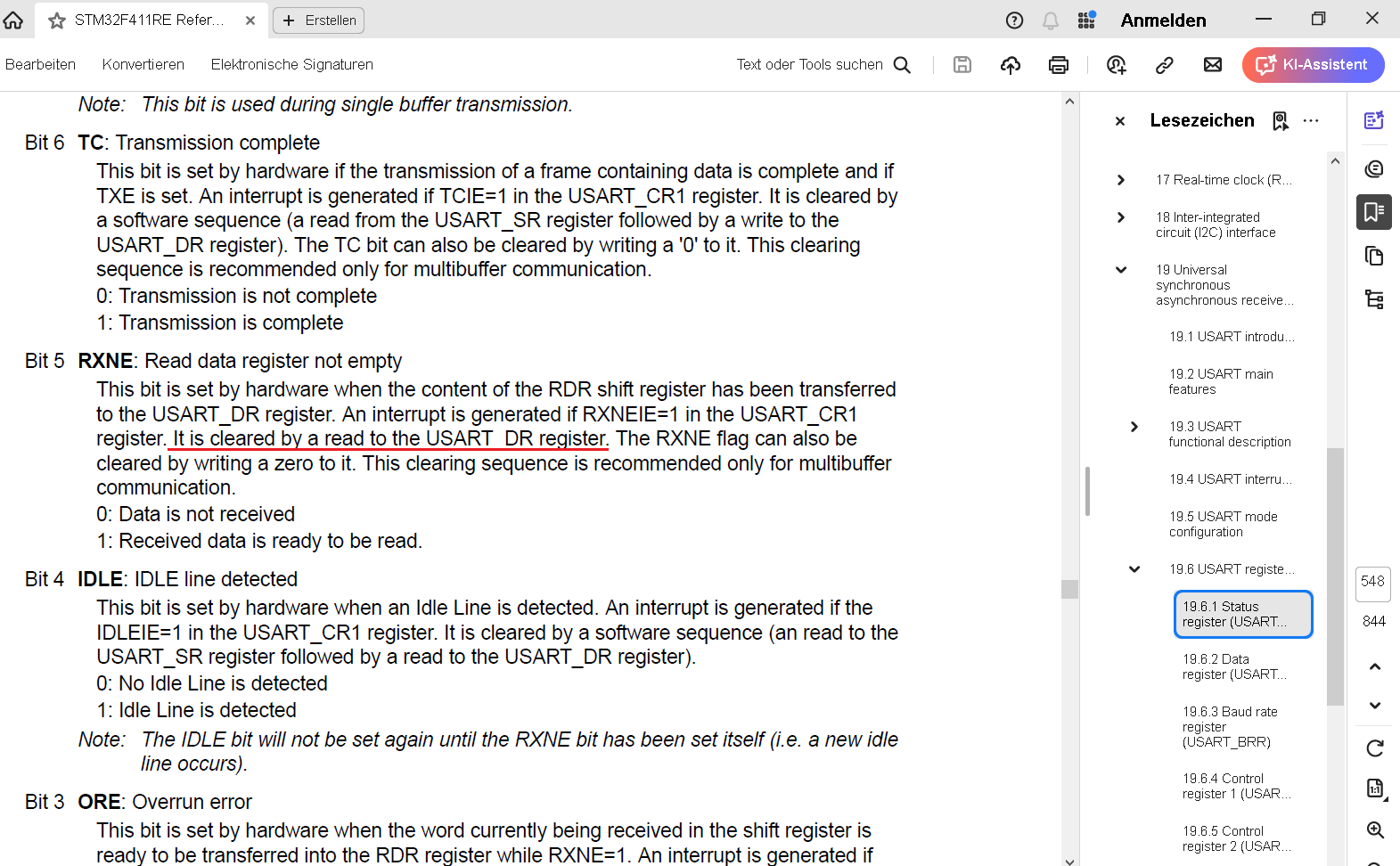
Datenblatt Ausschnitt STM32F411RE USART Register
STM32F411RE Refer... Erstellen Anmelden KI-Assistent Note: This bit is used during single buffer transmission. Bit 6 TC: Transmission complete This bit is set by hardware if the transmission of a frame containing
in „stm32f411 USART2 will nicht wie er soll“ · Mikrocontroller und Digitale Elektronik · · Screenshots
-
Datei
stm32_ST3210C_Eval_eeproM.c
#define EEPROM_I2C_ADDR 0xA0 #define I2C_SELECTED I2C1 void I2C_Configuration(void) { I2C_InitTypeDef I2C_InitStructure; GPIO_InitTypeDef GPIO_InitStructure; /* I2C Periph clock enable */ RCC_APB1PeriphClockCmd(RCC_APB1Periph_I2C1, ENABLE); /* GPIO Periph clock enable */ RCC_APB2PeriphClockCmd(RCC_APB2Periph_GPIOB | RCC_APB2Periph_AFIO, ENABLE); // /* GPIO_PinRemapConfig(GPIO_Remap_I2C1, ENABLE); */ /* Configure I2C_EE pins: SCL and SDA */ GPIO_InitStructure.GPIO_Pin = GPIO_Pin_6 | GPIO_Pin_7; GPIO_InitStructure.GPIO_Speed = GPIO_Speed_50MHz; GPIO_InitStructure.GPIO_Mode = GPIO_Mode_AF_OD; GPIO_Init(GPIOB, &
in „STM32 Prüfen ob I2C Slave am Bus hängt“ · Mikrocontroller und Digitale Elektronik ·
-
Datei
startup_stm32f10x_ld_vl.s
** ****************************************************************************** * @file startup_stm32f10x_ld_vl.s * @author MCD Application Team * @version V3.3.0 * @date 04/16/2010 * @brief STM32F10x Low Density Value Line Devices vector table for RIDE7 * toolchain. * This module performs: * - Set
in „STM32-Discoveryboard: FTDI Treiber/OpenOCD/Degugging“ · Mikrocontroller und Digitale Elektronik ·
-
Datei
stm32f103zet6_cantest_send.c
uint16_t CAN_ID; uint8_t CAN_DATA0,CAN_DATA1,CAN_DATA2,CAN_DATA3,CAN_DATA4,CAN_DATA5,CAN_DATA6,CAN_DATA7; uint8_t CanFlag; int main(void) { // Initialiesieren der CAN-Hardware CAN_Configuration(); printf("CAN-Bus Test \r\n"); printf("CAN-Bus Speed 100kHz \r\n"); /* Infinite loop */ while (1) { delay_ms(1000); /* delay 1000ms */ CanWriteData(0xA5A5); } } void CanWriteData(uint16_t ID) { CanTxMsg TxMessage; uint32_t i = 0; uint8_t TransmitMailbox = 0; /* transmit */ TxMessage.StdId = ID; //TxMessage.ExtId = 0x00; TxMessage.RTR = CAN_RTR_DATA; TxMessage.IDE = CAN_ID_STD; TxMessage.DLC = 8; TxMessage.Data
in „STM32 can Message“ · Mikrocontroller und Digitale Elektronik ·
-
Datei
stm32f103vct6_cantest_receive.c
uint16_t CAN_ID; uint8_t CAN_DATA0,CAN_DATA1,CAN_DATA2,CAN_DATA3,CAN_DATA4,CAN_DATA5,CAN_DATA6,CAN_DATA7; uint8_t CanFlag; int main(void) { // Initialiesieren der CAN-Hardware CAN_Configuration(); printf("CAN-Bus Test \r\n"); printf("CAN-Bus Speed 100kHz \r\n"); /* Infinite loop */ while (1) { if(CanFlag==ENABLE) { CanFlag=DISABLE; printf("CAN Receive Data \r\n"); printf("CAN_ID %x \r\n",CAN_ID); printf("CAN_DATA0 %x \r\n",CAN_DATA0); printf("CAN_DATA1 %x \r\n",CAN_DATA1); printf("CAN_DATA2 %x \r\n",CAN_DATA2); printf("CAN_DATA3 %x \r\n",CAN_DATA3); printf("CAN_DATA4 %x \r\n",CAN_DATA4); printf("CAN_DATA5
in „STM32 can Message“ · Mikrocontroller und Digitale Elektronik ·
-
Datei
STM32H753BIT6_Linker_Script.ld
ENTRY(ISR_RESET) MEMORY { FLASH_BANK_1 (rx) : ORIGIN = 0x08000000, LENGTH = 1024K FLASH_BANK_2 (rx) : ORIGIN = 0x08100000, LENGTH = 1024K SRAM_ITCM (rwx) : ORIGIN = 0x00000000, LENGTH = 64K SRAM_DTCM (rwx) : ORIGIN = 0x20000000, LENGTH = 128K SRAM_AXI (rwx) : ORIGIN = 0x24000000, LENGTH = 512K SRAM_1 (rwx) : ORIGIN = 0x30000000, LENGTH = 128K SRAM_2 (rwx) : ORIGIN = 0x30020000, LENGTH = 128K SRAM_3 (rwx) : ORIGIN = 0x30040000, LENGTH = 32K SRAM_4 (rwx) : ORIGIN = 0x38000000, LENGTH = 64K SRAM_BACKUP (rwx) : ORIGIN = 0x38800000, LENGTH = 4K SRAM_EXT_SDRAM (rwx) : ORIGIN = 0xC0000000, LENGTH = 8M
in „GCC Discarded Section in Disassembly“ · Mikrocontroller und Digitale Elektronik ·
-
PDF
STM32F107-SK-SCH-revA.pdf
TCKIN 44 BOOT0 PB15/SPI2_MOSI/TIM1_CH3N8 TDOIN TRESIN GND C77 470pF 100nF 47uF/6.3V/TANT TDOIN 3 STM32F103C8T6(PGM) 6 6 R3 1 6 47k C87 R76 R78 ) C81 5 C 4 R13 AUDIO_OUT_L R24 TRIM 10k 10k m + 8 V AN_TR , C55 N 3 33k 2.2uF/6.3V 10k 330R +C54 WKUP 8 100nF 47uF/6.3V/TANT G x 2 7 C78 10uF/6.3V/TANT R77
in „Cortex M3 STM32F107VC beim Reset passiert nichts“ · Mikrocontroller und Digitale Elektronik ·
-
Datei
startup_stm32f10x_md_vl.s
*************** (C) COPYRIGHT 2010 STMicroelectronics ******************** ;* File Name : startup_stm32f10x_md_vl.s ;* Author : MCD Application Team ;* Version : V3.3.0 ;* Date : 04/16/2010 ;* Description : STM32F10x Medium Density Value Line Devices vector table ;* for EWARM5.x toolchain. ;* This module
in „IAR for ARM - IRQ-Funktion nur kompiliert wenn im Code referenziert“ · Mikrocontroller und Digitale Elektronik ·
-
Datei
stm32f1xx_hal_msp_-_slave.c
/** ****************************************************************************** * File Name : stm32f1xx_hal_msp.c * Description : This file provides code for the MSP Initialization * and de-Initialization codes. ****************************************************************************** ** This
in „STM32F103 SPI Slave + Master“ · Mikrocontroller und Digitale Elektronik ·
-
Datei
stm32f103c8_flash.ld.txt
-------------------------------------------- * Linker script for running in internal FLASH on the STM32F103C8 *----------------------------------------------------------------------------*/ OUTPUT_FORMAT("elf32-littlearm", "elf32-littlearm", "elf32-littlearm") OUTPUT_ARCH(arm) SEARCH_DIR(.) /* Memory
in „ROM-Auslastung von C++-Programm reduzieren“ · Mikrocontroller und Digitale Elektronik ·
-
PDF
STM32-P207-P407_rev_D.pdf
C86 C91 3 4 1M A10 23 A10 I/O10 31 D10 J1 JOYSTICK 1 C1+ 2 2 1 C1+ 2 k C SD/MMC A11 24 A11 32 D11 STM32F207ZET6 100nF 2 C88 RX_BOOT_E TX_BOOT_E 100nF 2 C93 R 1 R29 0R A12 25 A12 I/O11 35 D12 UP UP LEFLEFT RM5G4 LEFT 3 C1- V+ 100nF Open Open 3 C1- V+ 100nF SD_D3/USART3_RX/SPI3_MISO R24 NA 2 CD/DAT3/CS
in „Mit STM32F4 einen Laser ansteuern“ · Mikrocontroller und Digitale Elektronik ·
-
PDF
MK_STM32F4_Sensorboard_Schematic-2.pdf
SPI3_2_MOSI GND + 1 2 VREF+ PA3/USART2_RX USART2_RX C5 GND SDO 5 SPI3_2_MISO 1 CS SPI3_CS_BMA180 STM32F407VGT_SORT Not in use 6 NC 4 VREF+ 11 NC INT INT_BMA180 V U$100 V 2 4 5 0 0 12 NC 3 3 A A A B B B C C C C C C C C D E E E E E E GND NC D + + P P P P P P P P P P P P P P P P P P P P P D D D 4 VCC ENABLE
in „EAGLE: Sprungfahnen“ · Platinen ·
-
PDF
STM32F407ZET6_sch-1.pdf
▯ ▯▯ ▯▯ 3*▯ ▯▯ ▯▯ ▯▯ ▯▯ 3*▯ ▯▯ ▯▯ 3)▯▯ 3*▯ ▯▯ ▯▯ 3*▯ ▯ 3(▯ ▯▯ ▯▯ 3*▯ 3*▯ ▯▯ ▯▯ 3*▯ ▯▯▯9▯UHJXODWRU STM32-USB Slave ,) JTAG/SWD ▯,) ISP 6HULDO▯,) 3(▯ ▯▯ ▯▯ 3(▯ 3'▯▯ ▯▯ ▯▯ 3'▯▯ ▯ 3(▯▯ ▯▯ ▯▯ 3(▯▯ 3'▯▯ ▯▯ ▯▯ 3'▯▯ 3(▯▯ ▯▯ ▯▯ 3(▯▯ 3'▯▯ ▯▯ ▯▯ 3'▯▯ 3(▯▯ ▯▯ ▯▯ 3(▯▯ 3'▯ ▯▯ ▯▯ 3'▯ 3%▯▯ ▯▯ ▯▯ 3%▯▯ 3%▯▯ ▯▯ ▯▯ 3%▯▯ 95()▯ 3%▯▯ 3%▯▯ *1' %227▯ 5▯▯ ▯▯ ▯▯ 3%▯▯%227▯ ▯▯ ▯▯ ▯▯ ▯▯ ▯9▯ ▯▯ ▯▯ ▯▯▯5 ▯▯ ▯▯ ▯9 ▯▯ ▯▯ *1' STM32F407ZET6 ▯9▯ ,2B▯▯;▯ ▯9▯ ,2B▯▯;▯ ▯9▯ 4▯ RAM ˖ 192K ▯ ▯ H[WHQG▯ I/O ▯ ▯ 9%$7 FLASH ˖ 512K *1' ▯ ▯ &▯ %$7▯▯& ▯▯▯ %▯ )UHTXHQFH˖ 16M8 Hz &5▯▯▯▯ *1' 3$▯▯:.B83 ▯▯ ▯▯▯ 3(▯ )60&B1%/▯ *1' 3$▯ ▯▯ 3$▯▯:.83▯8▯B
in „STM32F407 Black und Arduino“ · Mikrocontroller und Digitale Elektronik ·
-
PDF
Schaltplan_FARBE.pdf
1 2 3 4 5 6 D1 R1 PF6 3V3 JP3 JP1 JP2 470R 1 2 PE3 1 2 PE2 PE1 1 2 PE0 U1 STM32F103ZET6 D0 PD14 3 4 PD15 D1 PE5 PE4 PB9 PB8 WAKEUP_BUTTON PA0 34 106 LED1 D2 PD0 PD1 D3 VBAT 3 4 PE6 PB7 3 4 PB6 BLACK_LIGHT PA1 35 PA0-WKUP/USART2_CTS/ADC123_IN0/TIM5_CH1/TIM2_CH1_ETR/TIM8_ETR NC
in „STM32 Port-Initialisierung“ · Mikrocontroller und Digitale Elektronik ·
-
Datei
main.c
/* Includes ------------------------------------------------------------------*/ #include "stm32f10x.h" #include "main.h" /** @addtogroup STM32F10x_StdPeriph_Examples * @{ */ /** @addtogroup GPIO_IOToggle * @{ */ /* Private typedef -----------------------------------------------------------*/
in „STM32 SPI2 als Master sendet nichts“ · Mikrocontroller und Digitale Elektronik ·
-
Datei
hse_auto_clock.c
/* Automatische Erkennung von ext. HSE-Takt für STM32F7xx. Michael Nowak 2019-05-07 www.mino-elektronik.de */ #include "stm32f7xx.h" #define SOLLFREQUENZ_MHZ 216 // Vorgabewert #define PLL_M 16 // für internen HSI Takt #define PLL_Q 7 #define PLL_N (SOLLFREQUENZ_MHZ
in „STM32F429-Discovery Recycling: 90 MHz Frequenzzähler mit TFT“ · Projekte & Code ·
-
Datei
spi_oled.c
#include "STM32F4xx.h" #include "_mcpr_stm32f407.h" #include "spi_oled.h" #include "tools.h" #include "timer.h" void spiInit(void) { //CONFIGURE I/Os FOR SPI2 //SCLK = PB13 setOutputPort(B, 13, ALTERNATIVE, PUSHPULL
in „0,96 Oled mit STM32F407“ · Mikrocontroller und Digitale Elektronik ·
-
Datei
main.c
include <stdint.h> #include <stdbool.h> // Bibliotheke des verwendeten Mikrocontrollers #include "stm32f446xx.h" #include "system_stm32f4xx.h" // Funktionsprototypen void initialisiereClock(void); void initialisiereGPIO(void); void initialisiereSPI(void); void initialisiereSystick(void); void sendeBytesUSART
in „ADC über SPI“ · Mikrocontroller und Digitale Elektronik ·
-
PDF
1.5inch_RGB_OLED_Module_User_Manual_EN.pdf
GND. And the data transmitted are 9bit instead of 8bit. 4 / 8 1.5inch RGB OLED Module HOW TO USE STM32, Arduino and Raspberry Pi sample code is provided for this OLED. The sample code is used to draw shapes and display string. STM32 CONNECTION: The demo code is based on XNUCLEO-F103RB 1.5inch RGB OLED
in „DEBO OLED2 0.96 0,96" OLED-Display SSD1306 SSD1312 Initialisierung TWI I2C AVR ATmeg8 Assembler ASM“ · Projekte & Code ·