die bekannten 0,7V. Und auch da reicht es noch nicht ganz. Du brauchst auch keine 10A Diode. Nimm 3x 1N4001 in Reihe und gut. Damit werden ca. 2V Spannungsabfall erzeugt und alles ist im Lot.
---- Falk B. schrieb im Beitrag #6835997: > Nimm 3x 1N4001 in Reihe und gut. Damit werden ca. 2V Spannungsabfall > erzeugt und alles ist im Lot. Nicht ganz. Das untere Limit ist auch noch da: Umin=10.8V Meine erste Idee war, mehrere Dioden zu verwenden
master up to 12MBit/sec With USB you need a microcontroller that handles • Drives a LED matrix up to 8x64 with external all the protocol work to do the same thing. Several shift registers standard commands need to be supported to get a • Drives a 8x8 key or switch matrix device accepted as a USB device
master up to 12MBit/sec With USB you need a microcontroller that handles • Drives a LED matrix up to 8x64 with external all the protocol work to do the same thing. Several shift registers standard commands need to be supported to get a • Drives a 8x8 key or switch matrix device accepted as a USB device
Plateaus und vielleicht eine schwache Linie dazwischen: https://encrypted-tbn0.gstatic.com/images?q=tbn%3AANd9GcSTwdwB0mBN3TH_bpPiAKTWonYgzE8V-Z8Mlg&usqp=CAU Der zweite beim Betrachten eines Sinus mit hoher Frequenz bei geringer Abtastrate. Da wird dann im Digscope ein um Vielfaches langwelligerer Sinus
den 80ern auch schon > eingespart. Wie viel VA sollte der denn liefern? Amazon hat einen mit 2x3VA 2x20V https://www.amazon.de/Printtrafo-Trafo-230V-Durchsteckmontage-2-Ausg%C3%A4nge/dp/B08242V4Y2/ref=sr_1_6?__mk_de_DE=%C3%85M%C3%85%C5%BD%C3%95%C3%91&dchild=1&keywords=printtrafo+20v&qid=1609594794&
equivalent of 8 bit CRC used in 1-Wire devices X0 X1 X2 X3 X4 X5 X6 X7 X8 Input The hardware equivalent of the 16 bit CRC used in some 1-Wire devices is shown in Figure 12. The blocks represent the individual bits in a 16 bit shift register. The 16 15 2 equivalent polynomial is X + X + X + 1. 7 2579A-AVR-09/04 Figure 12. Hardware equivalent of 16 bit CRC used in 1-Wire devices 0 1 X2 X3 X4 5 6 7 X X X X X 8 9 10 11 12 13 14 15 16 Input X X X X X X X X X Implementation Three different
building a tilt compensated electronic compass using an LSM303DLH sensor module. The LSM303DLH is a 5 x 5 x 1 mm with LGA-28L package IC chip that includes a 3D digital linear acceleration and a 3D digital magnetic sensor. It has a selectable linear acceleration full scale range of ±2g / ±4g / ±8g and
products/uno-r4-wifi wechselt die größere Variante um 25 EUR den Besitzer. Neben einem auf einem ESP32-S3 basierenden Funkmodul bringt sie eine LED-Matrix (12x8 rote LEDs) mit. 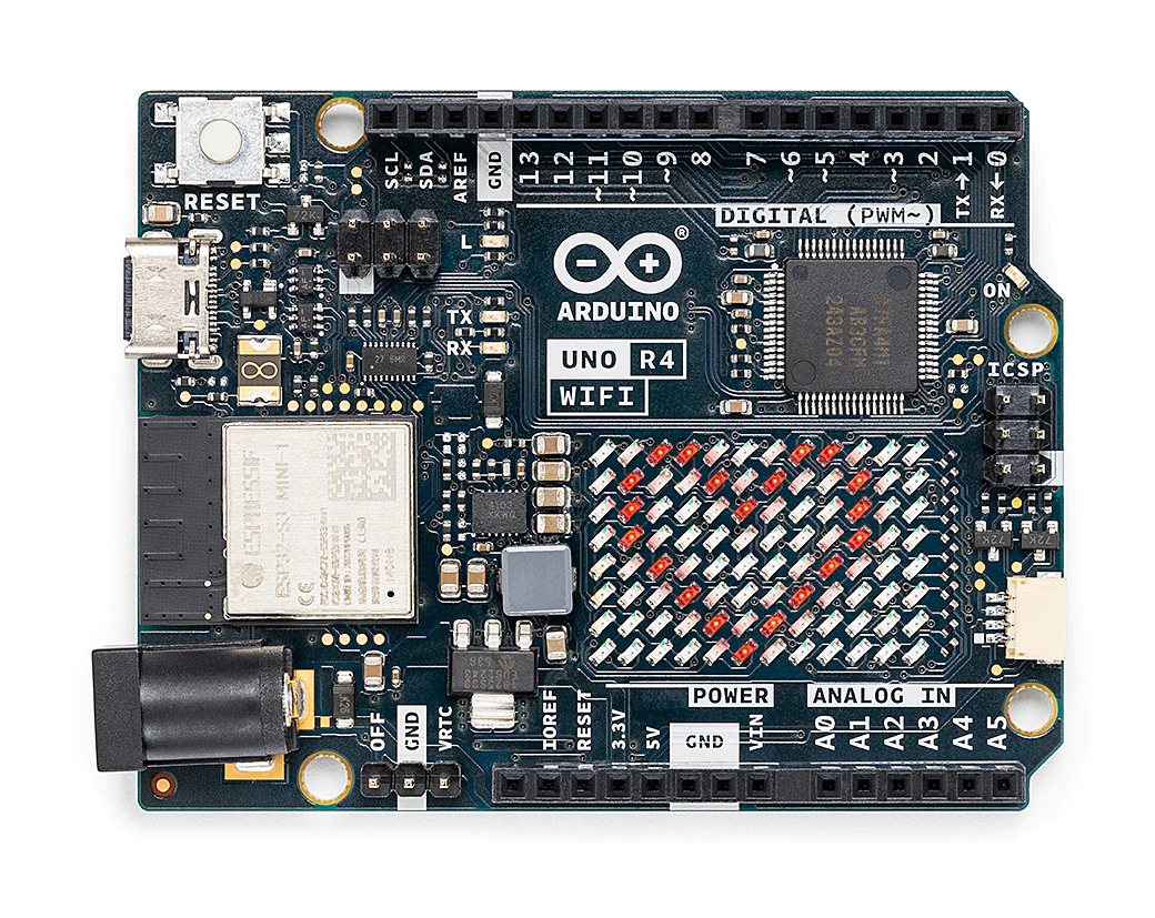 Bildquelle: Arduino Bei sorgfältiger Betrachtung fällt ein QWIIC-Interface auf, das einen
könnte man sich so etwas mit den etwas einfacheren Varianten der RISC-V-µCs von WCH bauen, der CH32V103x8x6 wäre da ein Kandidat. Kann mit 5V betrieben werden (also nicht nur 5V-tolerante I/Os), 20 kiB RAM, 64 kiB Flash, bis zu 72 MHz CPU-Takt, LQFP/QFN48 und LQFP64. Ist wohl was die Peripherie angeht,
auf das 4-Pin, I2C NONAME OLED ohne erkennbare Einschränkungen. Verwendete Initialisierung: U8G2_SH1106_128X64_NONAME_F_HW_I2C u8g2(U8G2_R0, U8X8_PIN_NONE); oder mit SDA / SCL: U8G2_SH1106_128X64_NONAME_F_HW_I2C u8g2(U8G2_R0, U8X8_PIN_NONE, D1, D2); Bei Verwendung der Instantiierung im Page-Modus erscheint keinerlei Anzeige auf dem OLED: U8G2_SH1106_128X64_NONAME_1_HW_I2C u8g2(U8G2_R0, U8X8_PIN_NONE); oder mit SDA / SCL: U8G2_SH1106_128X64_NONAME_1_HW_I2C u8g2(U8G2_R0, U8X8_PIN_NONE, D1, D2); Es gibt dabei weder Kompilierungs- noch
for deriving real capacitance without being affected by Rs and Rp. 10.5 1.0 Rp 10.4 0.9 C 150 k 10.3 0.8 10 pF Rs 10.2 Cs = 10.11 pF 0.7 ) 70 0 ) 0.6 ( p 10.1 Cs o e a Xc = 15.9 k at 1 MHz n 10.0 0.5 n c Cp t p 9.9 0.4 i C i Cs = C + 1 9.8 Cp = 9.89 pF 0.3 D 2CRp 2 9.7 0.2 CRp 2 D Cp = (Rs + Rp) 2 +
points. 2-8 IM OR100E-01E 2.3 Connecting the Signal Cable Specifications 788031 (when connected to the OR100E/OR300E) Input type : Common ground within the same probe Floating between recorder and probe Number of
beschrieben messen. Auf den Pins 1,6 und 8 habe ich stets 5V gemessen. Der Pin 3 (CS) hatte keine Spannung anliegend. Da unser Programmiergerät (Elnec Smartprog2) das HML nicht hinterlegt hat, können wir dies so nicht auslesen. Tipps wie es
Beni Z. schrieb im Beitrag #6746911: > Wir haben momentan einen alten BMW E30 M3 bei uns in der Werkstatt. Bei > diesem ist der Codierstecker im Kombiinstrument defekt. Dieser kleiner > Codierstecker hat ein PROM drin mit der Bezeichnung HML 087. Vermutung ist serielles
beiden binären .a library Files patchen. Das kann man z.B. mit folgenden Kommando machen, aber vorher \x00\x01\x02..\x0f durch den echten Key ersetzen. Woher man den bekommt habe ich oben unter "Schlüsselerlebnisse" geschrieben (wird dort Master Key genannt): [pre] bbe -e "s/\xd0\xd1\xd2\xd3\xd4\xd5\xd6\xd7\xd8\xd9\xda\xdb\xdc\xdd\xde\xdf/\x00\x01\x02\x03\x04\x05\x06\x07\x08\x09\x0a\x0b\x0c\x0d\x0e\x0f/" -o libzboss.a.patched libzboss.a [/pre] bbe ist ein binär Streameditor, den bekommt man z.B. bei Sourceforge
transmitters of a multiceiver-group. // rf_channel RF frequency channel to use: F(RF) = 2400 + x [MHz], where x = 0..125 void lib_nRF24L01_init_nRF24L01( uint8_t mode, uint8_t groupID, uint8_t deviceID, uint8_t rf_channel) { // the nRF24L01+ power on reset procedure needs 100ms after operating
to avoid repeated transmission collisions, ensure different values for each device working on the same RF-channel if ( mode == lib_nRF24L01_TXmode ) { uint8_t delay = (0x10 * (1+deviceID)) & nRF_REGBITMASK_SETUP_RETR_ARD; // see nRF_REGVAL_SETUP_RETR_ARD_*-constants lib_nRF24L01_set_regbyte
Serial.begin(115200); } void loop() { Serial.println(analogRead(0)); delay(100); } 3) Hardware: Entweder Wemos D1 oder ESP8266 direkt: Vcc, Reset, EN direkt auf +3,3V v. Spannungsregler GND, GPIO15 direkt auf GND GPIO0 10k pullup gegen 3,3V, per Taster gegen GND TX/RX
Hallo, rechnen kann ich auch nicht mehr, ich meinte ja 64... 2x MCP23S17 am SPI hätten 32 I/O die man Byteweise ansprechen kann. 3x 8 Ausgänge und 1x 8 um den Analog-Mux anzusprechen. Mehr als 10MHz SPI-Clock können die aber wirklich nicht, meine laufen mit 8MHz
2x3 macht 4 schrieb im Beitrag #6995695: > Schon hart, was heute von den Studierenden so verlangt wird. Noch erschreckender ist, dass im ersten Semester E-Technik Textaufgaben aus der 8./9. (?) Klasse
Wolfgang schrieb im Beitrag #6995704: > Noch erschreckender ist, dass im ersten Semester E-Technik Textaufgaben > aus der 8./9. (?) Klasse abgeprüft werden müssen. Ein guter Didaktiker weiß, wie wertvoll die 50-Euro-Frage bei Jauch ist; ein guter Prüfer erst recht.
for Atmel ARM Embedded processors: 4.8.4.371 [RELEASE NOTES] 7 42368-MCU-/ 5. New and Noteworthy This chapter lists the new and noteworthy items for the ARM GNU Toolchain release. 5.1 Supported devices SAM3A SAM3N SAM3S SAM3U SAM3X SAM4C SAM4E SAM4L SAM4N SAM4S SAM4SP SAM7S/SE SAM7X/XC SAM7L SAM9XE SAM9N SAM9R SAM9G SAM9X SAM9M SAMD SAMG SAMR 5.2 Noteworthy ● ARM GDB built from gdb 7.8. See "Source code" section in this document for more
Noch eine Anmerkung, dein Abbildungsfunktion f(x) = calc_new_value(x) liefert Ergebnisse aus f(x) E {0,..,255} und die Argumente x sind ebenfalls aus der Menge {0,..,255}. Somit kann man sich einfach eine Funktionstabelle F(x) mit 256 Werten im Flash
im Beitrag #7754997: > Ich habe gerade übers Wochenende einen Fuatba SBUS-Decoder (100.000 Baud > 8E2, RX invers) in Micro Phyton für den RPi Pico geschrieben. Geht > sicher auch für den ESP32. > Mein Fazit – ja Modellbau geeignet. Dito hier für ein Tyco Rebound RC Car. SBUS Dekoder, 2 x ESC,
Reaktionen neigen wenn man den normalen Bereich (1000µs…1500µs…2000µs) verlässt. [code]#!/usr/bin/python3 # -*- coding: utf-8 -*- SERVO_MIN = -110 SERVO_MAX = +110 def set_servo(percent): percent = max(SERVO_MIN, min(percent, SERVO_MAX)) duty_ns = ((percent + 100) / 200 + 1) * 1e6
rst byte of the payload acts as selector, a comprehensive description can be found in table 4. Table 3 Register values for zoom ranges Range Hex Data Range Hex Data 50 m 0xf4,0x01,0,0 2 km 0x20,0x4e,0,0 75 m 0xee,0x02,0,0 3 km 0x30,0x75,0,0 100 m 0xee,0x03,0,0 4 km 0x40,0x9c,0,0 250 m 0xc4,0x09,0,0 6 km 0x60,0xea,0,0 500 m 0x88,0x13,0,0 8 km 0x80,0x38,1,0 750 m 0x4c,0x1d,0,0 12 km 0xc0,0xd4,1,0 1 km 0x10,0x27,0,0 16 km 0x00,0x71,2,0 1.5 km 0x98,0x3a,0,0 24 km 0x80,0xa9,3,0 A Digital Interface for a Lowrance
anschliessbar. >> Daten des Displays: >> GTT043NDH02 >> Interface RGB 24 Bit >> 40 pol FPC >> 4.3" >> 480x272 > > Gibt es dazu ein Datenblatt? google GTT043NDH02 http://www.good-display.com/downloadRepository/25b02b07-77eb-4cd7-9300-1f765e2c9aec.pdf
is the same state as returned by the separate Winmon command CommandGetSetDeviceState 7.3.2 .The <state> field is available in Multi firmware versions >= 207 <State> Meaning 0x0 Down 0x1 Startup 0x2 Off 0x3 Slave
of line 2 */ #define LCD_START_LINE3 0x14 /**< DDRAM address of first char of line 3 */ #define LCD_START_LINE4 0x54 /**< DDRAM address of first char of line 4 */ #define LCD_WRAP_LINES 0 /**< 0: no wrap, 1: wrap at
different port for the LCD pins. * * The four LCD data lines and the three control lines RS, RW, E can be on the * same port or on different ports. * Change LCD_RS_PORT, LCD_RW_PORT, LCD_E_PORT if you want the control lines on * different ports. * * Normally the four data lines should
vs. Drain Current and Gate Voltage Capacitance 10 1.7 D = 9.3 A ) ( 8 VGS = 10 V,DI = 9.3 A e V = 20 V e 1.4 t DS n o t ) V 6 i d r V = 32 V e i u DS - a S n r 1.1 VGS = 4.5 VD I = 8.1 A t - o e 4 n ( a S G D -S R 0.8 G 2 V 0 0.5 0 10 20 30 40 50 - 50 - 25 0 25
Ultralight, Milfare DESFire und NTAG 203 alle mit dem gleichen "NFC-IC"? Weil einmal liest man was von 3DES Verschlüsslung, AES Verschlüsslung oder gar keiner Verschlüsslung!? Nur wie kommuniziere ich mit diesen Chips über einen einfachen 8-bitter wie den Atmega? Dazu fand ich bisher leider fast gar
Ich glaube nicht, dass die Standardreader DES können. Geschweige denn 3DES, was ja einfach nur 3xDES ist, da DES ja als "knackbar" gilt. Ein Indiz wäre auch, dass NXP die ICs in Kategorien aufteilt. Und z.B. unter den MIFARE SAMs ist "Ultralight C" zusammen mit den "DESfire
Example (10 chips) 0x0000000x1999990x3333330x4ccccc0x66666660x7fffff0x9999990xb333330xcccccc0xe6666661 As shown in figure 4-3, the 10 chips start to do hash calculation with their configured initial nonce after configuration
n c t i o n dx=Boost ( t , x ) R=30; Ue=5; C=20e-6; S= P u l s s i g n a l ( t ) ; if S==1 dx1=Ue / L( x ( 1 ) ) ; dx2=-x ( 2 ) / ( C*R) ; e l s e Fig. 11. Time traces of the inductor current for different duty cycles. dx1 =(Ue-x ( 2 ) -0 . 8 ) /L( x ( 1 ) ; dx2 =( x (1)-x ( 2 ) /R) /C; The most interesting aspect of the simulation results is the if ( ( x(1)<=0)&&(dx1 <0)) increase of the ripple current of the inductor with higher duty dx1
T T I L A I N NI N T T C L A I N NI I I I / C D C C C I I / C D C C P C P T / S/P / / / P / T 5 4 3 2 / 0 D D S C C C C2 0 D D S C C C C N X X E D D D D N X X E D D D D ( ( R(R ( ( A(A ( ( ( ( R(R ( ( A(A ( ( 2 1 0 6 5 4 3 2 D D D C C C C C P P P P P P P P P P P P P P P P 2 1 0 9 8 7 6 5 2 1 0 9 8
bidirectional I C-bus and SMBus voltage-level translator VSSOP8: plastic very thin shrink small outline package; 8 leads; body width 2.3 mm SOT765-1 D E A X c y H E v A Z 8 5 Q A2 A pin 1 index A 1 (A3) θ Lp 1 4 detail X L e w bp 0 5 mm scale Dimensions (mm are the
bidirectional I C-bus and SMBus voltage-level translator VSSOP8: plastic very thin shrink small outline package; 8 leads; body width 2.3 mm SOT765-1 D E A X c y H E v A Z 8 5 Q A2 A pin 1 index A 1 (A3) θ Lp 1 4 detail X L e w bp 0 5 mm scale Dimensions (mm are the
bidirectional I C-bus and SMBus voltage-level translator VSSOP8: plastic very thin shrink small outline package; 8 leads; body width 2.3 mm SOT765-1 D E A X c y H E v A Z 8 5 Q A2 A pin 1 index A 1 (A3) θ Lp 1 4 detail X L e w bp 0 5 mm scale Dimensions (mm are the
bidirectional I C-bus and SMBus voltage-level translator VSSOP8: plastic very thin shrink small outline package; 8 leads; body width 2.3 mm SOT765-1 D E A X c y H E v A Z 8 5 Q A2 A pin 1 index A 1 (A3) θ Lp 1 4 detail X L e w bp 0 5 mm scale Dimensions (mm are the
bidirectional I C-bus and SMBus voltage-level translator VSSOP8: plastic very thin shrink small outline package; 8 leads; body width 2.3 mm SOT765-1 D E A X c y H E v A Z 8 5 Q A2 A pin 1 index A 1 (A3) θ Lp 1 4 detail X L e w bp 0 5 mm scale Dimensions (mm are the
[code] ./lpctool -d /dev/ttyUSB1 -i -v -e -a boop_rom.bin lpctool V0.9 This Software is free Software under GNU GPL 3 or later (c) 2007 Ch. Klippel <ck@mamalala.net> Info : erasing flash #0 before write Info : using flash #0 image
So meine Betty Läuft jetzt auch..... [code] pindrei@ThinkPad-X1:~/Projekte/Betty Boop/Swisscom$ lpctool -d /dev/ttyUSB0 -i -v -e -a boop_rom.bin lpctool V0.9 This Software is free Software under GNU GPL 3 or later (c) 2007 Ch. Klippel <ck@mamalala.net>
AREF GND 5 20 AGND (T0/PSCOUT22) PC2 6 19 AVCC (T1/PSCOUT23) PC3 7 18 PC5 (ADC9/AMP1+) (MISO/PSCOUT20) PB0 8 17 PC4 (ADC8/AMP1-) 9 1 1 1 1 1 1 1 1 1 2 4 5 6 7 2 B E E D D D D B ) ) ) ) P)P) ) ) 2 L L A 2 0 0 1 T A A K P N M N U X X C C / C 5 C B 0 / / P ( C S 0 C
