-
 Bild
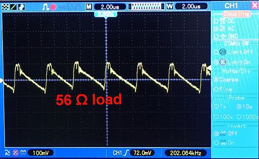
Oszilloskop-Messung eines Signals mit 56 Ohm Last
CH1 2.00us 2.00us 56 Ω load AC 20 100mV CH1 72.0mV 202.064kHz
in „Praktische Erfahrungen mit 1,5V AA LiIon Akkus?“ · Analoge Elektronik und Schaltungstechnik · · Fotos
-
PDF
AVR-Tutorial.pdf
LCD lcd_command: ; wie lcd_data, nur ohne RS zu setzen mov temp2, temp1 swap temp1 andi temp1, 0b00001111 out PORTD, temp1 rcall lcd_enable andi temp2, 0b00001111 out PORTD, temp2 rcall lcd_enable rcall delay50us ret ; erzeugt den Enable-Puls lcd_enable: sbi PORTD, 5 ; Enable
in „AVR-Tutorial als PDF bzw *.doc“ · Mikrocontroller und Digitale Elektronik ·
-
PDF
ETM0430G0DH6.pdf
CORPORATION E T M 0 4 3 0 G 0 D H 6 2 0-1 DOC . FIRST ISSUE JUL.13, 2011 R E C O R D S OF R E V I S I O N REVISED D A T E PAGE S U M M A R Y NO. JUL.27, 2011 9 6.1 OPTICAL CHARACTERISTICS THE BRIGHTNESS OF MODULE : MIN
in „LCD-Display an Raspberry PI“ · Analoge Elektronik und Schaltungstechnik ·
-
 Bild
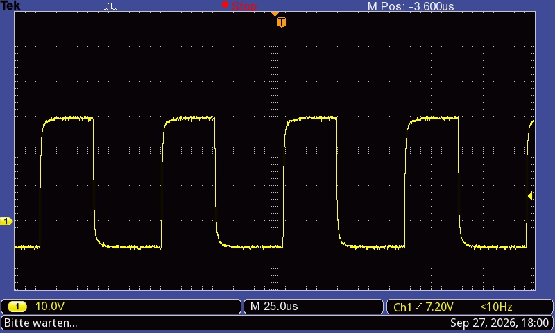
Oszilloskop-Messung eines Rechtecksignals
Tek Stop M Pos: -3.600us 1 10.0V M 25.0us Ch1 / 7.20V <10Hz Bitte warten... Sep 27, 2026, 18:00
in „"Reparatur"-Bericht Samsung TV - RU-Serie - Bootloop wegen CVK-Lines“ · Analoge Elektronik und Schaltungstechnik · · Oszi-Bilder

-
 Bild
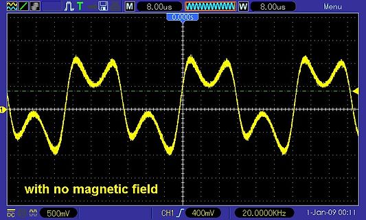
Oszilloskop-Screenshot eines Wellenverlaufs
8.00us W 8.00us Menu 0.000s with no magnetic field 500mV CH1 400mV 20.0000KHz 1-Jan-09 00:11
in „Physikprojekte“ · Offtopic · · Oszi-Bilder
-
 Bild
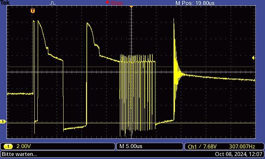
Oszilloskop-Messkurve eines Signals
Tek Stop M Pos: 19.80us 1 2.00V M 5.00us Ch1 / 7.68V 307.007Hz Bitte warten... Oct 08, 2024, 12:07
in „Fritzbox 7590 fiept“ · PC Hard- und Software · · Oszi-Bilder
-
 Bild
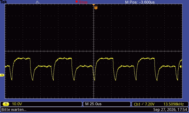
Oszilloskop-Messkurve eines Signals
Tek Stop M Pos: -3.600us 1 10.0V M 25.0us Ch1 / 7.20V 13.5098kHz Bitte warten... Sep 27, 2026, 17:54
in „"Reparatur"-Bericht Samsung TV - RU-Serie - Bootloop wegen CVK-Lines“ · Analoge Elektronik und Schaltungstechnik · · Oszi-Bilder

-
 Bild
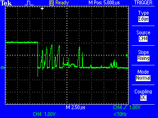
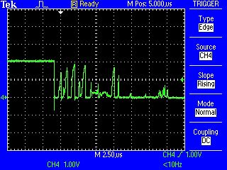
Oszilloskop-Messkurve eines Signals
Tek Ready M Pos: 5.00us TRIGGER Type Edge Source CH4 Slope Rising Mode Normal Coupling DC 4 CH4 1.00V M 2.50us CH4 1.00V <10Hz
in „Handbetriebenen Drehgeber ohne Timer auswerten“ · Mikrocontroller und Digitale Elektronik · · Oszi-Bilder
-
PDF
RK7Segment-Testsheet.pdf
# 35$ 36 % 37 & 38 ' 39( 40 ) 41 * 42 + 43 , 44- 45 . 46 / 47 2 ! " # $ % & ' ( ) * + , - . / 0 48 1 49 2 50 3 514 52 5 53 6 54 7 558 56 9 57 : 58 ; 59 < 60= 61 > 62 ? 63 3 0 1 2 3 4 5 6 7 8 9 : ; < = > ? @ 64 A 65 B 66 C 67D 68 E 69 F 70 G 71H 72 I 73 J 74 K 75 L 76M 77 N 78 O 79 4 @ A B C D E F G
in „S: 7 Segment lookup Table für Buchstaben“ · Softwareentwicklung ·
-
PDF
Strom-Messen.pdf
minimizes intrusiveness by of a 1m precision sensing resistor, direct AC-to-DC acting as a small in-line power adaptor. The male plug recti▯cation, and the ADE7753 energy meter IC. ACme- of the appliance is inserted into the female receptacle
in „Auftrag zu vergeben“ · Markt ·
-
 Bild
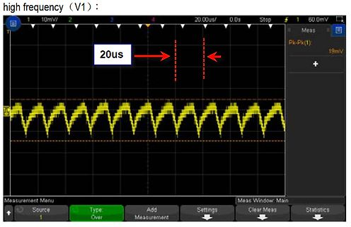
Oszilloskop-Messung eines periodischen Signals
high frequency (V1) : 10mV/ 20.00us/ 0.0s Stop Meas Pk-Pk(1): 19mV 20us Measurement Menu Source Type: Over Add Measurement Settings Clear Meas Statistics Meas Window: Main
in „Schaltfrequenz Meanwell RT-65 Serie“ · Analoge Elektronik und Schaltungstechnik · · Oszi-Bilder
-
PDF
MP205.pdf
Maximum conditions at 25°C ITEM MAXIMUM UNIT CONDITIONS LV ST HS Supply energy (25°C) 0.26 0.7 0.2 mJ/dot Print Cycle (25°C) 2.5 5.0 1.25 ms/line Supply voltage 7.2 8.5 8.5 volts Logic voltage 7 volts Head Temperature 65 °C Number of dots to be energized 192 dots simultaneously 1 1/ If energy above
in „Flexprint to USB - LTP1245(Drucker) - Platinendesign“ · Mikrocontroller und Digitale Elektronik ·
-
PDF
Gooligum.pdf
for each time we re-configure the voltage reference), it makes sense to define it as a macro: ; 10 us delay ; (assuming 4 MHz processor clock) Delay10us MACRO goto $+1 ; 2 us delay * 5 = 10 us goto $+1 goto $+1 goto $+1 goto $+1 ENDM This Delay10us’ macro can then be used to add the necessary 10 µs delay
in „PIC10F202/etc: Programmierung unter Linux(Ubuntu)“ · Mikrocontroller und Digitale Elektronik ·
-
PDF
Hameg_Encoder_ALPS-EC11J.pdf
. 250VDC Type c e Voltageproof 300V AC for 1minute 50V AC for 1minute 300V AC for 1minute e M f c Rotational torque 7mN・m max. m h a n Detent torque 12±5mN・m 40±20mN・m 8±5mN・m c a e l Push-pull strength 100N e v Cold –40±2℃ for 240h –40±3℃ for
-
PDF
MPVD7N65.pdf
I 28 A DM Single avalanche current(Note 2) I 7.0 A AS Single pulsed avalanche energy(Note 2) E 245 mJ AS Repetitive avalanche current(Note 1) AR 5.5 A Repetitive avalanche energy (Note 1) EAR 2.9 mJ Power dissipation PD 58 W Junction temperature TJ 150 C Storage temperature range T stg -55~150 C *
in „Unbekannte Bauelemente“ · Analoge Elektronik und Schaltungstechnik ·
-
PDF
Simple-circuits-reduce-regulator-noise-floor.pdf
preamps, I used a standard load value of 600 Ohms because in a nominal 12- volt circuit this gives us a load current of 20 mA, which is a typical load for such circuits. Figure 7 is a comparison of the performance of the Capacitance Multiplier of Figure 1 and the LM317 used as a noise source. The capacitance
in „Spannung filtern, wie macht man es richtig?“ · Analoge Elektronik und Schaltungstechnik ·
-
PDF
Speedballmanual_02-03-14.pdf
) ( ) 2—150K 2W metal film resistor (brown, green, yellow, gold) ( ) 1 - Speedball manual CDROM Some of the parts included in your kit my vary slightly from the descriptions here. Occasionally parts can be mis-packed, so call us at 360-697-1936 if you have problems finding
in „150V DC für Röhrenverstärker erzeugen“ · Analoge Elektronik und Schaltungstechnik ·
-
PDF
BUT11AX_1.pdf
sustaining voltage IB= 0 A; IC= 100 mA; 450 - - V L = 25 mH V CEsat Collector-emitter saturation voltages I =C2.5 A; I =B0.5 A - - 1.5 V V Base-emitter saturation voltage I = 2.5 A; I = 0.5 A - - 1.3 V h BEsat DC current gain I = 5 mA; V
in „BUT11AX mit BUT11AF austauschen?“ · Mikrocontroller und Digitale Elektronik ·
-
PDF
datasheet.pdf
Resistance R L Single-ended 16 Ω Seek/Tune Time (effective channel) 50 ms/ch Power-up Time 380 ms Notes: 1. FMOD=1kHz, 75us de-emphasis 2. MONO=1 3. △F=22.5kHz 4. V =1mV, Frx=70MHz~110MHz EMF 5. AGCD=1 6. △F=75kHz 7. VOLUME<3:0>=1111 8. The supported RCLK frequency is not continuous. Please refer to application
in „Stm32f4 I2C 16Bit auslesen“ · Mikrocontroller und Digitale Elektronik ·
-
PDF
AVR_tutorial.pdf
ret ; Und wieder zurück ; Pause nach jeder Übertragung delay50us: ; 50us Pause ldi temp1, $42 delay50us_:dec temp1 brne delay50us_ ret ; wieder zurück ; Längere Pause für manche Befehle delay5ms: ; 5ms Pause ldi temp1, $21 WGLOOP0: ldi temp2, $C9 WGLOOP1: dec temp2
in „AVR-Tutorial als PDF bzw *.doc“ · Mikrocontroller und Digitale Elektronik ·
-
PDF
Datenblatt_EBMPapstLuefter.pdf
= 0 40 W 90 W 83,0 W P +- 10 % +- 10 % +- 10 % Tolerance PWM 0010 Current consumption ∆p = 0 2.500 mA 3.800 mA 2.750 mA Tolerance I +- 10 % +- 10 % +- 10 % PWM 0010 Speed ∆p = 0 7.300 1/min 9.500 1/min 9.500 1/min n +- 7,5 % +- 7,5 % +- 7,5 % Tolerance PWM 0010 01/31/2019 page 6 of 16 Product Data Sheet
in „EBM Papst 4114 Lüfter mit Microcontroller steuern“ · Analoge Elektronik und Schaltungstechnik ·
-
PDF
GH79L4N_FEB2002_.pdf
-13h0m to +13h0m m PDOP value Yes 6 0 to 10 t Elevation Angle Mask Yes 5 deg. 5 to 90 deg. r Geodetic ID Yes 1 (WGS84) 1 to 171 s Mask by Elevation Angle for Yes 5 deg. 5 to 90 deg. Receivable Satellites Prediction
in „GPS Receiver Furuno / Tecsys GH-79“ · Mikrocontroller und Digitale Elektronik ·
-
Datei
572727.tex
. (radarange) & 1 \\ \hline Thomas F. (igel) & 1 \\ \hline Stefan W. (stefan\_w234) & 1 \\ \hline Rolf (rolf22) & 1 \\ \hline Richard Z. (richard\_z65) & 1 \\ \hline G. K. (zumsel) & 1 \\ \hline M. E. (engelhard) & 1 \\ \hline Max (max\_y) & 1 \\ \hline Detlev T. (detlevt) & 1 \\ \hline Flöte (nsolo) & 1 \\ \hline Georg M. (g\_m) & 1 \\ \hline Max (max\_u) & 1 \\ \hline Michael B. (alter\_mann) & 1 \\ \hline Axel S. (a-za-z0-9) & 1 \\ \hline
in „Wirklich nutzbare Alternative zu Word un Excel?“ · PC Hard- und Software ·
-
Datei
LCD-Test2.asm
: push temp1 ldi temp1,0x00 out PORTB, temp1 rcall delay1s rcall delay1s ldi temp1,0xFF out PORTB, temp1 pop temp1 ret ; Pause nach jeder Übertragung delay50us: ; 50µs Pause (bei 4 MHz) ldi temp1, $42 delay50us_:dec temp1 brne delay50us_ ret ; wieder zurück ; Längere Pause für manche Befehle delay5ms: ; 5ms Pause (bei 4 MHz) push temp1 push temp2 ldi temp1, $21 WGLOOP0: ldi temp2, $C9 WGLOOP1: dec temp2 brne WGLOOP1 dec
in „Displaytech 162C Init fehlgeschlagen“ · Mikrocontroller und Digitale Elektronik ·
-
PDF
datasheet.pdf
M X 2 5 L 1 6 0 5 D M X 2 5 L 3 2 0 5 D M X 2 5 L 6 4 0 5 D 16M-BIT [x 1 / x 2] CMOS SERIAL FLASH 32M-BIT [x 1 / x 2] CMOS SERIAL FLASH FEATURES 64M-BIT [x 1 / x 2] CMOS SERIAL FLASH GENERAL • Serial Peripheral
in „MX25L160(5AM2C) neu beschreiben? Gibt es eine DIY Lösung?“ · Mikrocontroller und Digitale Elektronik ·
-
Datei
dogm132-5_atmega8_8mhz.asm
DOG_PORT, DOG_RESET rcall delay50us cbi DOG_PORT, DOG_RESET rcall delay50us sbi DOG_PORT, DOG_RESET rcall delay1ms DOG_INIT: ldi DOG_CMD, $40 ; DISPLAY START rcall SPI_cmd_send ldi DOG_CMD, $A1 ; ADC REVERSE rcall SPI_cmd_send ldi DOG_CMD
in „ATMEGA8 mit Grafik-Display DOGM-132-5 in Assembler“ · Mikrocontroller und Digitale Elektronik ·
-
PDF
From_analog_to_digital_-_p281.pdf
60 10 50 8 10k 100k 1M 10M 100M 1G fin[Hz] Fig. 24: ADC resolution vs. input frequency and clock jitter 15 295 J. B ELLEMAN In the light of these considerations, it is evident that the clock of high-performance ADCs should
in „SNR bei ADCs“ · Analoge Elektronik und Schaltungstechnik ·
-
Datei
dogm132-5_atmega8_8mhz.asm
out DOG_PORT, temp1 ; ; ; SPI Modul konfigurieren ; clr temp1 ldi temp1, (1<<SPE) | (1<<MSTR) out SPCR, temp1 DOG_INIT_RESET: sbi DOG_PORT, DOG_RESET rcall delay50us cbi DOG_PORT, DOG_RESET rcall delay50us sbi DOG_PORT,
in „ATMEGA8 mit Grafik-Display DOGM-132-5 in Assembler“ · Mikrocontroller und Digitale Elektronik ·
-
Datei
lcd.c
; LCD_PORT &= 0xF0; LCD_PORT |= temp1; // setzen lcd_enable(); _delay_ms(5); temp2 = temp2 & 0x0F; LCD_PORT &= 0xF0; LCD_PORT |= temp2; // setzen lcd_enable(); _delay_us(42); } // sendet einen Befehl an das LCD void lcd_command(unsigned
in „ATmega8 LCD HD44780 Initialisierung“ · Mikrocontroller und Digitale Elektronik ·
-
PDF
spectrum-allocations-posterLR.pdf
e e i a n ii t e a - e ) 2 2 2 ) 0 2 2 8 2 2 2 0 2 - 2 2 2 0 0 5 2 2 8 0 2 0 0 - 5 6 1 2 2 2 - 2 0 a 2 J o p o t t e g t m W T 6 0 1 00 1 0 1 1 4 1 0 0 4 0 - 0 0 1 4 4 5 1 0 a 4 1 l 0 2 4 6 7 0 0 0 - 0 0 o 1 t c e k u m S r r c 3 c a 0 4 0 5 1 4 4 + 4 0 0 g 0 9 0 n 4 u i ( 4 0 r a 4 g
-
Datei
control-codes.txt
Character Set UK --> G0 ESC ( B SCS Select Character Set US ASCII --> G0 ESC ( 0 SCS Select Character Set DEC special characters and line drawing set --> G0 ESC ) A SCS Select Character Set UK --> G1 ESC ) B SCS Select Character Set US ASCII --> G1 ESC ) 0 SCS
-
Datei
Wattmeter_v1.4.c
; // OCR1B default Value --> 1ms OCR1B = Lower_end; } void Timer2_init(void) { //F_CPU/1024 (32.7680 mSec Overflow) TCCR2B |= (1<<CS22) | (1<<CS21) | (1<<CS20); //Allow Overflow Interrupt TIMSK2 |= (1<<TOIE2);
in „Problem mit delay.h und Optimierungsstufe v. AVR Studio 4“ · Mikrocontroller und Digitale Elektronik ·
-
Datei
partdb-autoprice.py
/5.0 (X11; U; Linux ppc; en-US; rv:1.9.0.12) " +\ "Gecko/2009072221 Iceweasel/3.0.6 (Debian-3.0.6-1)", "Accept" : "text/html,application/xhtml+xml,application/xml;q=0.9,*/*;q=0.8", "Accept-Language" : "en-us,en;q=0.5", "Accept-Charset
in „PART-DB RW 1.2“ · Projekte & Code ·
-
PDF
ToneLabSE_Service_manual.pdf
ADAPTOR KA-163EV M.PART 117CN 1 405014000 AC/AC ADAPTOR KA-163EV M.PART 117US 1 405014000 AC/AC ADAPTOR KA-163EV M.PART 117EX 1 405014100 AC/AC ADAPTOR KA-169EV M.PART 230UK 1 405014100 AC/AC ADAPTOR KA-169EV M.PART 230WG
in „74 HC 595 Defekt feststellen?“ · Mikrocontroller und Digitale Elektronik ·
-
Datei
ADS1256_022.c
TMR2 = 0; // Timer reset, dmit der erste Clock Impuls normale Länge hat SSPBUF = Daten; // 1 Byte: 1 = Setze Ausgang while (!BF) continue; // Warten bis Übertragung fertig ist / 1 = fertig ; _delay (80); // 80 = 8 us Datenblatt t6= min. 7 us return SSPBUF; // und Puffer auslesen } //********
in „ADS1255 / ADS1256 Beispielcode“ · Mikrocontroller und Digitale Elektronik ·
-
Datei
file-1.php
WW ÃF % p8Íaÿ g]Ź"e 9Næ)Ñ úÿ *Ñ; ŽÌûý&ÏX ÿ i"Ít ùHê ±Æ8úW?of·W °È¬Äf6 8èkè 7W° Á ºTö¶6 ó ä Ô ° 3 d Üs\€ ô9®M̺¯ # DXàóÓx sùS » õ= ö_øwàýnXιáM?T 0MÚ¹çŠN ¥Qøïðç@²Ö&[ OÒbÎDvql Û=þŽŸ ñ=¯ÃýçOñUÊ l*ÿ b$ªÃ róqù~5Gâ/ .Œmze Y¹œ à m6+f#è ©íPîÑG x öºe = 9Øó*1-ï ÏœgI¥Å Çr/ÚâweÚ²>æ$ 9úô®Ö]"ÚCûôŒº r ! > ¬eðª Æu
in „Sporadisches Sterben einzelner 2N3773 in Stromsenke bei höheren Spannungen“ · Analoge Elektronik und Schaltungstechnik ·
-
PDF
STAC9721T.pdf
Supply Current 28 mA PR1 +5V Analog Supply Current 37 mA PR2 +5V Analog Supply Current 28 mA PR3 +5V Analog Supply Current 1.1 mA PR0,1,2,3 +5V Analog Supply Current 0.6 mA PR4 +3.3V Digital Supply Current 0.1 mA PR4 +5V
in „[S] günstige Möglichkeit, zwei DC-Spannungen über mehrere Stunden zu überwachen“ · Markt ·
-
PDF
XLampXML2.pdf
junction to solder point °C/W 2.5 Viewing angle (FWHM) degrees 125 Temperature coefficient of voltage mV/°C -1.6 ESD withstand voltage (HBM per Mil-Std-883D) V 8000 DC forward current mA 3000 Reverse voltage V -5 Forward voltage (@ 700 mA, 85 °C) V 2.85 3.15 Forward voltage (@ 1500 mA, 85 °C) V 3.05 Forward
in „Li Akku effizient in WLED endladen“ · Analoge Elektronik und Schaltungstechnik ·
-
PDF
Gath_-_Triacs_und_Diacs_in_Theorie_und_Praxis.pdf
241-600 6,5 8 Schaltspan TAG 271-600 10 4 Type nung (V) Hal(mA)rom strom(mA)csteller TAG 256-800 12 8 Us Ih If TAG 251-800 10 8 TAG 266-800 10 5 4E20-8 20±4 1... 15 150 TAG 225-800 8 8 4E20-28 20±4 14...45 150 E TAG 226-800 8 8 4E30-8 30±4 1...45 150 ro TAG 227
in „hysteresefreie Phasenanschnittsteuerung“ · Analoge Elektronik und Schaltungstechnik ·
-
PDF
GWS6967.pdf
in g le P u ls e E 0 .0 1 1 .E -0 4 1 .E -0 3 1 .E -0 2 1 .E -0 1 1 .E + 0 0 1 .E + 0 1 1 .E + 0 2 S q u a re W a v e P u lse D u ra tio n (se c ) N o r m a liz e d T r a n s ie n t T h e r m a l Im p e d a n c e , J u n c tio n -to -F o o t 1 .0 0 d D u ty C y c le = 0 .5 i a r ( c 0 .2 a e m 0 .1 l 0 .1 0 m e 0 .0 5 T e s 0 .0 2 r e t 0 .0 1 e E S in g le P u ls e 0 .0 1 1 .0 E -0 4 1 .0 E -0 3 1 .0 E -0 2 1 .0 E -0 1 1 .0 E + 0 0 1 .0 E
in „Bauteilsuche Hexfet? Hilfe“ · Mikrocontroller und Digitale Elektronik ·
-
Datei
LCD_Test2.asm
;.include "c:\programme\Atmel\AVR Tools\avrassembler2\appnotes\m8515def.inc" .include "c:\programme\Atmel\AVR Tools\avrassembler2\appnotes\tn13def.inc" .def temp1 = r16 .def temp2 = r17 .def temp3 = r18 . .org $0000 rjmp reset reset: ldi temp1, LOW (RAMEND) ; LOW-Byte
in „LCD Routine funktioniert auf 8515 aber nicht auf Tiny13“ · Mikrocontroller und Digitale Elektronik ·
-
PDF
Compare_Parts.pdf
(nV/rtHz ) Vos (Offset 0.003 0.003 0.005 0.005 0.005 0.005 0.005 0.005 0.01 Voltage @ 25C) (Max ) (mV ) Iq per 1.3 1.5 1.7 0.95 0.6 0.6 0.285 0.285 0.007 channel (Typ ) (mA ) GBW (Typ ) 14 1.9 10 5 1.6 1.6 2 2 0.35 (MHz ) Slew Rate 20 2.8 5 2.6 1.5 1.5 1.6 1.6 0.16 (Typ ) (V/us ) Rail-to-Rail In to
in „Eingangs-Offset von OP-AMP extern kompensieren“ · Analoge Elektronik und Schaltungstechnik ·
-
PDF
Compare_Parts.pdf
(nV/rtHz ) Vos (Offset 0.003 0.003 0.005 0.005 0.005 0.005 0.005 0.005 0.01 Voltage @ 25C) (Max ) (mV ) Iq per 1.3 1.5 1.7 0.95 0.6 0.6 0.285 0.285 0.007 channel (Typ ) (mA ) GBW (Typ ) 14 1.9 10 5 1.6 1.6 2 2 0.35 (MHz ) Slew Rate 20 2.8 5 2.6 1.5 1.5 1.6 1.6 0.16 (Typ ) (V/us ) Rail-to-Rail In to
in „Wie perfekte ADC Werte 16Bit“ · Mikrocontroller und Digitale Elektronik ·
-
PDF
Compare_Parts.pdf
(nV/rtHz ) Vos (Offset 0.003 0.003 0.005 0.005 0.005 0.005 0.005 0.005 0.01 Voltage @ 25C) (Max ) (mV ) Iq per 1.3 1.5 1.7 0.95 0.6 0.6 0.285 0.285 0.007 channel (Typ ) (mA ) GBW (Typ ) 14 1.9 10 5 1.6 1.6 2 2 0.35 (MHz ) Slew Rate 20 2.8 5 2.6 1.5 1.5 1.6 1.6 0.16 (Typ ) (V/us ) Rail-to-Rail In to
in „Auswahl Operationsverstärker“ · Analoge Elektronik und Schaltungstechnik ·
-
PDF
Compare_Parts.pdf
(nV/rtHz ) Vos (Offset 0.003 0.003 0.005 0.005 0.005 0.005 0.005 0.005 0.01 Voltage @ 25C) (Max ) (mV ) Iq per 1.3 1.5 1.7 0.95 0.6 0.6 0.285 0.285 0.007 channel (Typ ) (mA ) GBW (Typ ) 14 1.9 10 5 1.6 1.6 2 2 0.35 (MHz ) Slew Rate 20 2.8 5 2.6 1.5 1.5 1.6 1.6 0.16 (Typ ) (V/us ) Rail-to-Rail In to
in „Messverstärkerschaltung für Raspberry Pi“ · Analoge Elektronik und Schaltungstechnik ·
-
PDF
Compare_Parts.pdf
(nV/rtHz ) Vos (Offset 0.003 0.003 0.005 0.005 0.005 0.005 0.005 0.005 0.01 Voltage @ 25C) (Max ) (mV ) Iq per 1.3 1.5 1.7 0.95 0.6 0.6 0.285 0.285 0.007 channel (Typ ) (mA ) GBW (Typ ) 14 1.9 10 5 1.6 1.6 2 2 0.35 (MHz ) Slew Rate 20 2.8 5 2.6 1.5 1.5 1.6 1.6 0.16 (Typ ) (V/us ) Rail-to-Rail In to
in „Gleichspannungsoffset ausgleichen“ · Analoge Elektronik und Schaltungstechnik ·
-
PDF
Compare_Parts.pdf
(nV/rtHz ) Vos (Offset 0.003 0.003 0.005 0.005 0.005 0.005 0.005 0.005 0.01 Voltage @ 25C) (Max ) (mV ) Iq per 1.3 1.5 1.7 0.95 0.6 0.6 0.285 0.285 0.007 channel (Typ ) (mA ) GBW (Typ ) 14 1.9 10 5 1.6 1.6 2 2 0.35 (MHz ) Slew Rate 20 2.8 5 2.6 1.5 1.5 1.6 1.6 0.16 (Typ ) (V/us ) Rail-to-Rail In to
in „Wie kann man ein 100 mv Spannugsquelle generieren?“ · Analoge Elektronik und Schaltungstechnik ·
-
PDF
Compare_Parts.pdf
(nV/rtHz ) Vos (Offset 0.003 0.003 0.005 0.005 0.005 0.005 0.005 0.005 0.01 Voltage @ 25C) (Max ) (mV ) Iq per 1.3 1.5 1.7 0.95 0.6 0.6 0.285 0.285 0.007 channel (Typ ) (mA ) GBW (Typ ) 14 1.9 10 5 1.6 1.6 2 2 0.35 (MHz ) Slew Rate 20 2.8 5 2.6 1.5 1.5 1.6 1.6 0.16 (Typ ) (V/us ) Rail-to-Rail In to
in „billige sehr gut erhältliche Instrumentenverstärker gesucht“ · Analoge Elektronik und Schaltungstechnik ·
-
PDF
Compare_Parts.pdf
(nV/rtHz ) Vos (Offset 0.003 0.003 0.005 0.005 0.005 0.005 0.005 0.005 0.01 Voltage @ 25C) (Max ) (mV ) Iq per 1.3 1.5 1.7 0.95 0.6 0.6 0.285 0.285 0.007 channel (Typ ) (mA ) GBW (Typ ) 14 1.9 10 5 1.6 1.6 2 2 0.35 (MHz ) Slew Rate 20 2.8 5 2.6 1.5 1.5 1.6 1.6 0.16 (Typ ) (V/us ) Rail-to-Rail In to
in „Operationsverstärker, bipolare Versorgung, Genauigkeit und Verstärkung um Nullpunkt“ · Analoge Elektronik und Schaltungstechnik ·
-
Datei
display.asm
andi r17, 0b00001111 ; Dann das niederwertige Nibble out PORTD, r17 rcall lcd_enable rcall delay50us ret lcd_data: ; Sendet das Byte aus r16 im 4-Bit Modus an das Display mov r17, r16 ; Höherwertige Nibble swap r16 andi r17, 0b00001111 sbr r16, 1<<4 ; RS wird auf 1 gesetzt out PORTD, r16 rcall lcd_enable andi r17, 0b00001111 ; Niederwertige Nibble sbr r17, 1<<4 ; RS wird auf 1 gesetzt out PORTD, r17 rcall lcd_enable rcall delay50us ret lcd_clear: ; Sendet dem Befehl zu löschen des Displays ldi r16, 0b00000001 rcall lcd_command rcall delay5ms ret delay50us
in „Display Evaluation Board Add On“ · Mikrocontroller und Digitale Elektronik ·