-
Bild
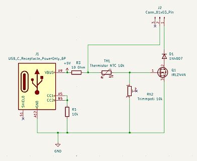
Schaltplan mit USB-C, NTC-Thermistor und MOSFET
J1 USB_C_Receptacle_PowerOnly_6P VBUS A9 R3 10 Ohm TH1 Thermistor NTC 10k J2 Conn_01x03_Pin 1 2 3 D1 1N4007 Q1 IRLZ44N 1 2 3 RV2 Trimpoti 10k CC1 A5 CC2 B5 R1 10k A12 SHIELD GND
in „Hilfe bei Temperatursteuerung“ · Analoge Elektronik und Schaltungstechnik · · Schaltpläne
-
Bild
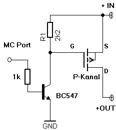
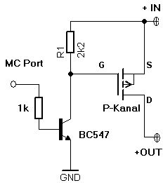
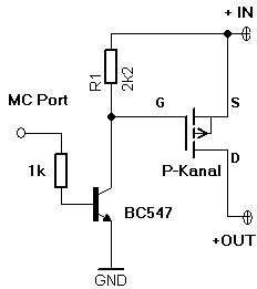
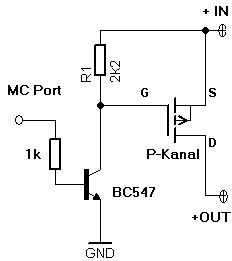
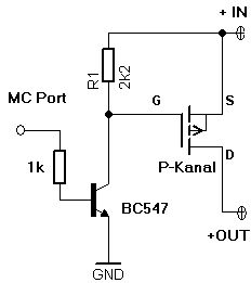
Schaltplan mit BC547 und P-Kanal MOSFET
+ IN, R1, 2k2, G, S, MC Port, 1k, P-Kanal, D, BC547, +OUT, GND
in „12V 2A per Raspberry Pi (3,3V) schalten“ · Analoge Elektronik und Schaltungstechnik · · Schaltpläne
-
Bild
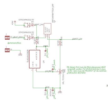
Schaltplan einer Batteriewächter-Schaltung mit MOSFET und TL431
muss die Minimalspannung UBAT eingestellt werden. Für LiFePo4 sind das etwa 10,4V, dann muss der MOSFET Q7 die restlichen Verbraucher abschalten. 10k TC33X-2-103E TM2 A-K-D GND J8-6 ON_Switch J8-12 OFF_Switch PSTA-12 GND
in „Bosch ProCore 18V Adapter mit BMS für Geräte anderer Hersteller“ · Analoge Elektronik und Schaltungstechnik · · Schaltpläne
-
Bild
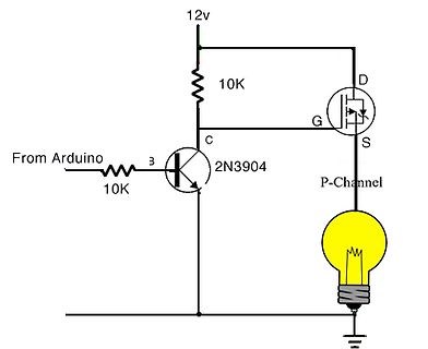
Schaltplan mit NPN-Transistor und P-Kanal MOSFET
12v 10K D G S P-Channel From Arduino 3 10K 2N3904 C
in „Probeschaltung mit Funktionsgenerator und (Labor)Netzteil testen“ · Analoge Elektronik und Schaltungstechnik · · Schaltpläne
-
Bild
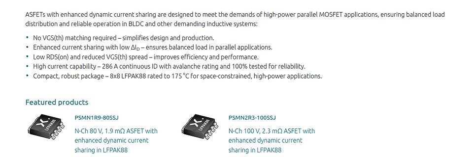
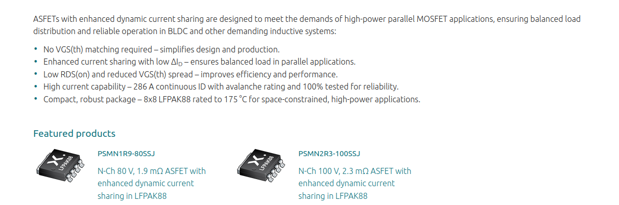
Produktbeschreibung von ASFETs für parallele MOSFET-Anwendungen
ASFETs with enhanced dynamic current sharing are designed to meet the demands of high-power parallel MOSFET applications, ensuring balanced load distribution and reliable operation in BLDC and other demanding inductive systems: • No VGS(th) matching required – simplifies design and production. • Enhanced
in „Hochleistungsoperationsverstärker, flexible Steckverbinder, Labormäntel und mehr“ · Mikrocontroller und Digitale Elektronik · · Screenshots
-
Bild
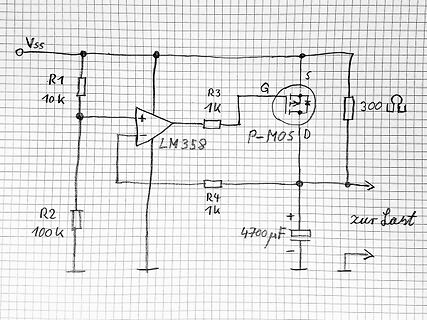
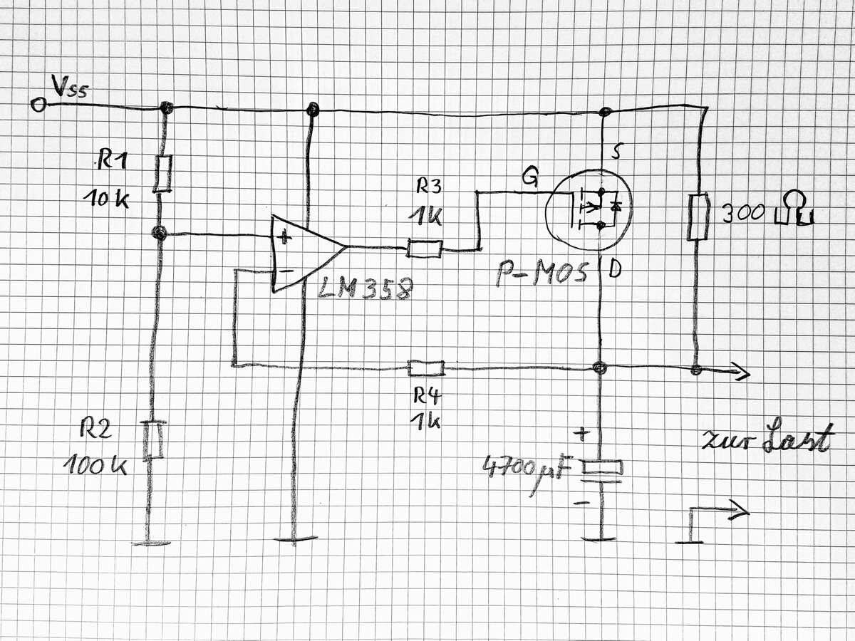
Handgezeichneter Schaltplan mit LM358 und P-MOSFET
Vss R1 10k R2 100k LM358 R3 1k G S P-MOS D 300 R R4 1k zur Last 4700uF
in „Mostet als inrush limiter schalter“ · Analoge Elektronik und Schaltungstechnik · · Schaltpläne
-
Bild
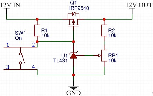
Schaltplan einer MOSFET-gesteuerten Schaltung mit TL431
12V IN Q1 IRF9540 12V OUT R1 10k R2 10k SW1 On 1 2 3 4 U1 TL431 RP1 10k GND
in „Over-Discharge Protection mit TL431 - Verständnisfrage“ · Analoge Elektronik und Schaltungstechnik · · Schaltpläne
-
Bild
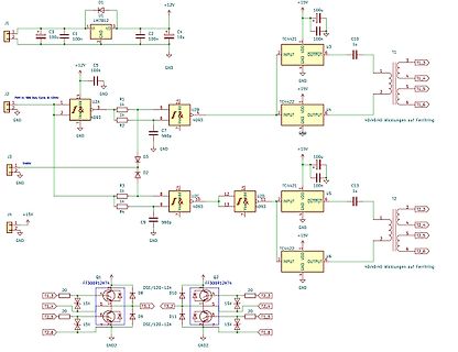
Schaltplan eines MOSFET-Treiber-Designs für Transformatoren
J1, +12V, C3 100u, C1 100n, U1 LM7B12, VD, C2 100n, C4 10u, GND, T1, T1_3, T1_4, T1_5, T1_6, 40:40 Wicklungen auf Ferritring, J2, PWM 50% Duty Cycle 8-12kHz, C5 100n, R1 1k, U2A 4093, R2 1k, C7 560p, U2B 4093, TC4421, INPUT, OUTPUT, J3, Enable, D3, D2, R3 1k, R4 1k, U2C 4093, U2D 4093, C9 560p, TC4421, U5, C13 1u, T2, T2_3, T2_4, T2_5, T2_6, TC4422, U6, J4, +15V, Q1 FF300R12KT4, Q2 FF300R12KT4, D8, D9, D10, D11, DSE/120-12A, T3_1, T3_2, T2_4, T1_5, T1_6
in „IGBT brennt durch / Schutzbeschaltung“ · Analoge Elektronik und Schaltungstechnik · · Schaltpläne
-
Bild
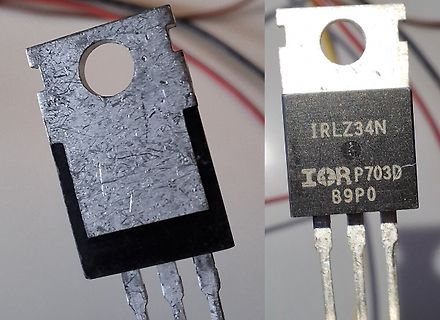
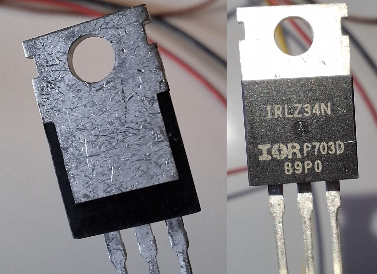
Zwei MOSFET-Bauteile im TO-220 Gehäuse
IRLZ34N IORP703D 89P0
in „Ersatztyp für "ND1X"“ · Analoge Elektronik und Schaltungstechnik · · Fotos
-
Bild
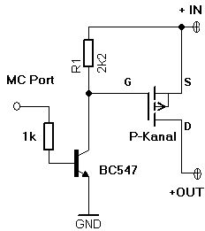
Schaltplan mit BC547 und P-Kanal MOSFET
MC Port, 1k, BC547, GND, R1, 2k2, G, S, P-Kanal, D, +IN, +OUT
in „PWM Lüfter Steuerung mit ESP8266 Tacho Problem“ · Mikrocontroller und Digitale Elektronik · · Schaltpläne
-
Bild
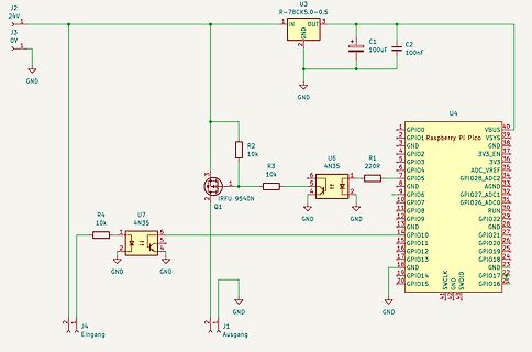
Schaltplan mit Raspberry Pi Pico und MOSFET-Treiber
J2 24V, J3 0V, U3 R-78CK5.0-0.5, C1 100uF, C2 100nF, U6 4N35, R1 220R, U4 Raspberry Pi Pico, GPIO0 bis GPIO26, VBUS, VSYS, 3V3_EN, ADC_VREF, AGND, GND, SWCLK, GND, SWDIO, R2 10k, R3 10k, Q1 IRFU 9540N, R4 10k, U7 4N35, J4 Eingang, J1 Ausgang
in „I/O-Beschaltung Raspberry Pico (für 24V)“ · Mikrocontroller und Digitale Elektronik · · Schaltpläne
-
Bild
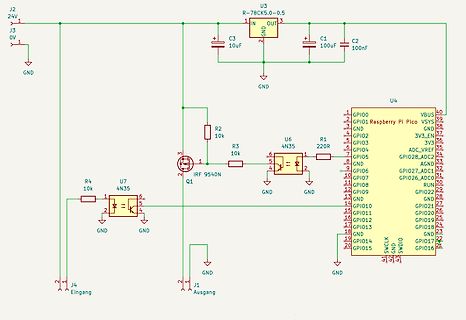
Schaltplan mit Raspberry Pi Pico und MOSFET-Treiber
J2 24V, J3 0V, U3 R-78CK5.0-0.5, IN, OUT, GND, C3 10uF, C1 100uF, C2 100nF, R2 10k, R3 10k, U6 4N35, R1 220R, Q1 IRF 9540N, R4 10k, U7 4N35, GND, J4 Eingang, J1 Ausgang, U4 Raspberry Pi Pico, GPIO0 bis GPIO28, VBUS, VSYS, 3V3_EN, 3V3, ADC_VREF, GND, SWCLK, GND, SWDIO
in „I/O-Beschaltung Raspberry Pico (für 24V)“ · Mikrocontroller und Digitale Elektronik · · Schaltpläne
-
Bild
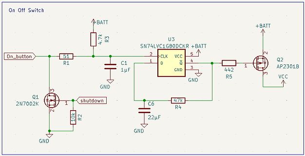
Schaltplan einer Ein-/Ausschaltung mit MOSFET und Monostabile Kippstufe
On Off Switch BATT R3 4.7k On_button R1 51 C1 1µF GND U3 SN74LVC1G80DCKR CLK 2 D 1 Q 4 VC C 5 GND 3 +BATT Q2 AP2301B R5 442 1 3 VCC Q1 2N7002K 3 1 2 shutdown R2 10k GND 47K R4 C6 22µF GND
in „ESP 32 (Mikrokontroller) Mittels FlipFlop oder Transistor nur bei Tastendruck an- bzw ausschalten“ · Mikrocontroller und Digitale Elektronik · · Schaltpläne
-
Bild
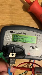
Atlas DCA Pro Messgerät mit MOSFET-Bauteil
atlas DCA Pro DCAZ5 on - test scroll - off PEAK N-Ch Enhancement mode MOSFET Red-S Green-D Blue-G
in „Mosfet BUZ80 defekt?“ · Analoge Elektronik und Schaltungstechnik · · Fotos
-
Bild
Schaltplan mit BC547 und P-Kanal MOSFET
MC Port, 1k, BC547, GND, R1, 2k2, G, S, P-Kanal, D, +IN, +OUT
in „Netzteil für Peltier-Element“ · Analoge Elektronik und Schaltungstechnik · · Schaltpläne
-
Bild
Schaltplan mit BC547 und P-Kanal MOSFET
MC Port, 1k, BC547, GND, R1, 2k2, G, S, P-Kanal, D, +IN, +OUT
in „Spannung für Mosfet vom ESP Mit LevelShifter anheben?“ · Analoge Elektronik und Schaltungstechnik · · Schaltpläne
-
Bild
Schaltplan mit BC547 und P-Kanal MOSFET
MC Port, 1k, BC547, GND, R1, 2k2, G, S, P-Kanal, D, +IN, +OUT
in „ESP32 fahrrad blinker mit warnblinker“ · Fahrzeugelektronik · · Schaltpläne
-
Bild
Schaltplan mit BC547 und P-Kanal MOSFET
MC Port, 1k, BC547, GND, R1, 2k2, G, S, P-Kanal, D, +IN, +OUT
in „12V 4A mit Mikrocontroller schalten?“ · Analoge Elektronik und Schaltungstechnik · · Schaltpläne
-
Bild
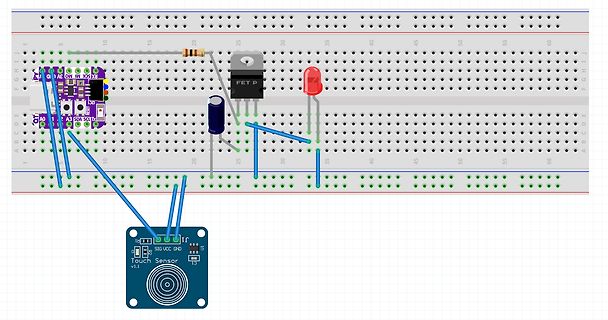
Virtueller Aufbau mit Breadboard, Touch Sensor und MOSFET
I2C, SDA, SCL, A0, A1, A2, FET P, SIG, VCC, GND, Touch Sensor v1.1
in „Summen am Netzteil mit PWM“ · Analoge Elektronik und Schaltungstechnik · · Screenshots
-
Bild
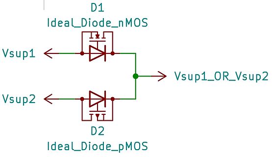
Schaltplan einer idealen Dioden-OR-Verknüpfung mit MOSFETs
D1 Ideal_Diode_nMOS Vsup1 D2 Ideal_Diode_pMOS Vsup2 Vsup1_OR_Vsup2
in „Ideale Diode Symbolvorschlag“ · Platinen · · Schaltpläne
-
Bild
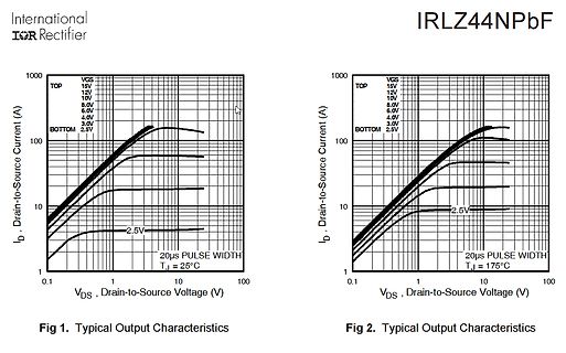
Kennlinien des IRLZ44NPbF MOSFETs
International IOR Rectifier IRLZ44NPbF Fig 1. Typical Output Characteristics ID, Drain-to-Source Current (A) VGS 15V 12V 10V 8.0V 6.0V 4.0V 3.0V 2.5V TOP BOTTOM 0.1 1 10 100 VDS, Drain-to-Source Voltage (V) Fig 2. Typical Output Characteristics 20us PULSE WIDTH TJ = 25°C 20us PULSE WIDTH TJ = 175°C
in „ESP32 mit 3,3V PWM einen 3,7V Motor betreiben“ · Analoge Elektronik und Schaltungstechnik · · Diagramme
-
Bild
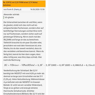
Forenbeitrag über ESP32 und MOSFET-Berechnung
Re: ESP32 mit 3,3V PWM einen 3,7V Motor betreiben von Frank O. (frank_o) 16.06.2026 12:56 Alexander schrieb: Ich glaube Der Unterschied zwischen dir und Hinz, wenn du glaubst, stützt sich nicht auf ein entsprechendes Fachwissen, sondern eher auf leichtfertige Vermutungen und bei Hinz nicht nur auf Fachwissen, sondern sicher auch auf jahrelanger Erfahrung. Nimm doch mal den IRLZ44N und fange an das zu berechnen. Vielleicht brauchst du ein paar Stunden oder, je nachdem wie weit dein Vorwissen ist, eine Woche, bis du das soweit verstehst, dass du das verstehen und berechnen kannst. Wenn du fertig bist, kannst
in „ESP32 mit 3,3V PWM einen 3,7V Motor betreiben“ · Analoge Elektronik und Schaltungstechnik · · Screenshots
-
Bild
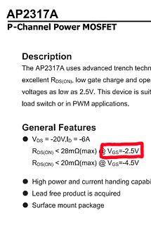
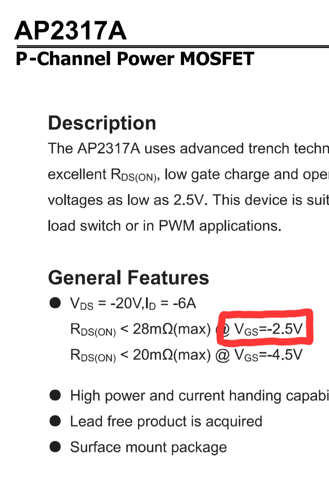
Ausschnitt eines Datenblatts für einen P-Channel MOSFET
AP2317A P-Channel Power MOSFET Description The AP2317A uses advanced trench techn... excellent RDS(ON), low gate charge and ope... voltages as low as 2.5V. This device is suit... load switch or in PWM applications. General Features
in „ESP32 mit 3,3V PWM einen 3,7V Motor betreiben“ · Analoge Elektronik und Schaltungstechnik · · Screenshots
-
PDF
IRF7822.pdf
PD - 94279 IRF7822 HEXFET Power MOSFET for DC-DC Converters N-Channel Application-Specific MOSFETs Ideal for CPU Core DC-DC Converters Low Conduction Losses Low Switching Losses 1 8 A S D 2 7 S D Description 3 6 This new device employs advanced HEXFET Power S D 4 5 MOSFET technology to achieve an unprecedented G D balance of on-resistance and gate charge.The reduced conduction and switching losses make it ideal for high SO-8 Top View efficiency DC-DC converters that
in „Falsches Ladegerät am Notebook :-(“ · Mikrocontroller und Digitale Elektronik ·
-
PDF
2xNMOS_IRF7103.pdf
PD - 9.1095B IRF7103 HEXFET Power MOSFET l Adavanced Process Technology l Ultra Low On-Resistance S1 1 8 D1 2 7 VDSS = 50V l Dual N-Channel MOSFET G1 D1 l SurfaceMount 3 6 S2 D2 R DS(on) = 0.130 l Available in Tape & Reel 4 5 l Dynamic dv
in „Spannungspeaks / Ripple durch Schaltregler. Abhilfe?“ · Analoge Elektronik und Schaltungstechnik ·
-
Datei
St_ckliste2.txt
? SMD N? R154 Spannungsschutz 1K? SMD 9 N 81 R145 Reset-ATmega32-Pull-UP 10k? SMD 1 N? R155-R162 Mosfet Pull-Down 1M? SMD 8 N? Sonstiges Transistor Lehrer SMD 64 J Mosfet IRFL014 SMD 8 J Microkontroler ATmega32 8bit Durchst.1 J Speicherregister74HC573 8bit Durchst.8 J Spannungs IC mit 3A/5V Durchst.1
in „Projekt LED-Cube 8x8x8“ · Mikrocontroller und Digitale Elektronik ·
-
PDF
ME4056.pdf
a ● Programmable charge current up to 1A t/ermally enhanced 8-PIN SOP package on the bottom ●No MOSFET sense resistor or blocking diode and low external component count make the ME4056 required ideally suited for portable applications. Furthermore the ●Complete linear Charger in SOP8 Package for ME4056
in „Eine sehr kleinen Akku laden“ · Analoge Elektronik und Schaltungstechnik ·
-
PDF
resteliste_1.pdf
€ AD1100A 10 SO8 Analog DevicesDUM1100 iCoupler 5,00 € BSP373 50 SOT223-4 Infineon Small-Signal MOSFET, 100V, SOT-223 5,00 € CA3240 E 50 DIL8 OP AMP DUAL MOS IP/BIPOLAR OPAMP 8,00 € ICL7660SCPA 20 DIL8 Ladungspumpenkonverter 10,00 € K6F8016U6D-XF55 20 SMD SAMSUNG 512K x16 bit Super Low Power and Low
in „Aufräumen und Reste“ · Markt ·
-
PDF
picaxe_manual3.pdf
1N4001 is suitable for this diode. 5V 1N4001 RL1 10k Pin BCX38B 0V Standard Circuits 4 - The Power MOSFET Interfacing Circuit Power MOSFETs can be used instead of darlington transistor pairs to switch medium power devices. The standard MOSFET circuit is shown below. The device IRF530 is a suitable power
in „8 leds an einen prot eines mc?“ · Mikrocontroller und Digitale Elektronik ·
-
PDF
class_E_amplifier_design_-_N_Sokal_QEX_Jan_2001.pdf
that time will be more than fast enough. stage. A planned subsequent article would drive a BJT or a MOSFET inter- The input-port characteristics of will discuss in detail a simple circuit changeably, with no change needed in the driver or in the PA input circuit. That driver BJTs, MOSFETs and MESFETs are
in „Class-E mit 1. oder 2. Oberwelle“ · HF, Funk und Felder ·
-
Datei
All.txt
16MHz CRYSTALHC49UP HC49UP CRYSTAL 1 Q1 TIP120 TIP120 TO220AL 1 Q1 PMOSFET_PTO220BH TO220BH Power MOSFET P-Channel 1 Q1 MOSFET-P-4D-FDC604P MOSFET-P-4D-FDC604P SOT23-6 P Channel Enhancement Mosfet with 4 Drain Pins 1 Q1 IRFU5305 IRFU5305 I-PAK_TO251AA HEXFET Power MOSFET 1 Q1 IRFR5305 IRFR5305 D2PACK HEXFET Power MOSFET 1 Q1 IRFP460 IRFP240 TO247BV HEXFET Power MosFet 1 Q1 IRFD9210 IRFD9210 DIL04 P-Channel Enhancement MOSFET 1 Q1 IRF7425 IRF7425 SO8 1 Q1 IRF7416 P-MOSFET-SO8 SO-08 P-Channel MOSFET 1 Q1 IRF740 IRF740
in „[KiCad] Bibliotheksaufbau - Konzeptideen gesucht“ · Platinen ·
-
PDF
P-MOSFETsi3445dv.pdf
Si3445DV Vishay Siliconix P-Channel 1.8-V (G-S) MOSFET FEATURES PRODUCT SUMMARY V (V) R (Ω) I (A) • Halogen-free According to IEC 61249-2-21 DS DS(on) D Definition 0.042 at GS = - 4.5 V ± 5.6 TrenchFET Power MOSFETs - 8 0.060 at GS = - 2.5 V ± 4.7 1.8
in „richtiger n-Kanal MOSFET, 3,3V soll 5V und 100mA schalten“ · Analoge Elektronik und Schaltungstechnik ·
-
PDF
SFS0405T4.pdf
SFS0405T4 N and P-CHANNEL POWER MOSFET GENERAL DESCRIPTION The SFS0405T4 uses advanced trench technology and design to provide excellentDS(ON)ith low gate charge. It can be used in a wide variety of applications. FEATURES ◆ N-CHANNEL V
in „Bezugsquelle oder Alternative gesucht.“ · Mikrocontroller und Digitale Elektronik ·
-
PDF
mx1508.pdf
The circuit integrates two H-channel drive circuits designed with N-channel and P-channel power MOSFETs, which are suitable for driving the steering of electric toy cars. Wheel and rear wheel drive, (drive brushed DC motor or drive two windings of stepper motor). The circuit has a wide operating voltage
in „MX1616H Dual H-Bridge Motor Driver“ · Analoge Elektronik und Schaltungstechnik ·
-
Bild
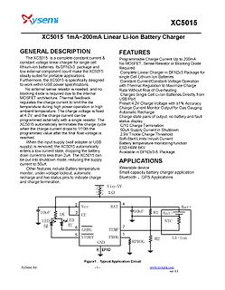
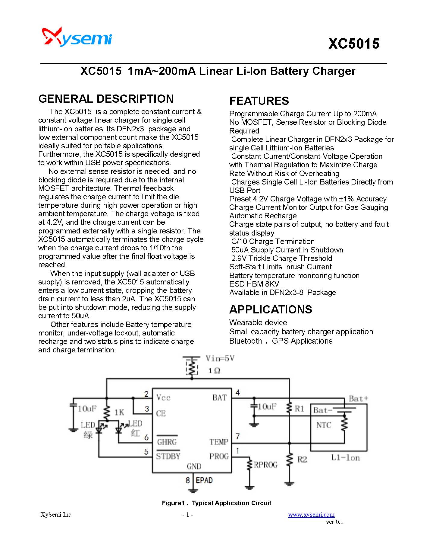
Datenblatt und Schaltplan des XC5015 Li-Ion Ladegeräts
specifications. No external sense resistor is needed, and no blocking diode is required for the MOSFET regulate the charge. Thermal feedback regulates the charge current to limit the temperature during high power charging or high ambient temperature. The charge voltage is fixed at 4.2V, and the charge
in „XC5015 XC7010 JW3510 Datenblatt gesucht DC DC Wandler“ · Analoge Elektronik und Schaltungstechnik · · Screenshots
-
PDF
irf7389.pdf
PD - 91645 IRF7389 PRELIMINARY ® HEXFET Power MOSFET l Generation V Technology N-CHANNEL MOSFET N-Ch P-Ch l Ultra Low On-Resistance S1 1 8 D1 l Complimentary Half Bridge G1 2 7 D1 l SurfaceMount V DSS 30V -30V S2 3 6 D2 l FullyAvalancheRated G2 4 5 D2 P-CHANNEL MOSFET R 0.029 0.058 DS(on) Description Top View FifthGenerationHEXFETsfromInternationalRectifier utilize advanced processing techniques to achieve extremely low on-resistance per silicon area. This benefit
in „Mini-FET's“ · Analoge Elektronik und Schaltungstechnik ·
-
PDF
IRF7389_N-P-Channel_30V_5.3A_0.058Ohm.pdf
PD - 91645 IRF7389 PRELIMINARY ® HEXFET Power MOSFET l Generation V Technology N-CHANNEL MOSFET N-Ch P-Ch l Ultra Low On-Resistance S1 1 8 D1 l Complimentary Half Bridge G1 2 7 D1 l SurfaceMount V DSS 30V -30V S2 3 6 D2 l FullyAvalancheRated G2 4 5 D2 P-CHANNEL MOSFET R 0.029 0.058 DS(on) Description Top View FifthGenerationHEXFETsfromInternationalRectifier utilize advanced processing techniques to achieve extremely low on-resistance per silicon area. This benefit
in „DC-Motor mit HIP2101“ · Mikrocontroller und Digitale Elektronik ·
-
PDF
AS1360_Datasheet_v1_03.pdf
1). Short Circuit/Overcurrent Protection The AS1360 monitors current flow through the p-channel MOSFET. In short-circuit or overcurrent conditions, the inte- grated short-circuit protection circuitry will limit output current. Note: Thermal Dissipation according to Absolute Maximum Ratings on page 3
in „Suche LDO mit Iss oder Iq >1uA.“ · Mikrocontroller und Digitale Elektronik ·
-
PDF
irf7389.pdf
PD - 91645 IRF7389 PRELIMINARY ® HEXFET Power MOSFET l Generation V Technology N-CHANNEL MOSFET N-Ch P-Ch l Ultra Low On-Resistance S1 1 8 D1 l Complimentary Half Bridge G1 2 7 D1 l SurfaceMount V DSS 30V -30V S2 3 6 D2 l FullyAvalancheRated G2 4 5 D2 P-CHANNEL MOSFET R 0.029 0.058 DS(on) Description Top View FifthGenerationHEXFETsfromInternationalRectifier utilize advanced processing techniques to achieve extremely low on-resistance per silicon area. This benefit
in „H-Brücke am µC“ · Analoge Elektronik und Schaltungstechnik ·
-
PDF
ON_AND8230D_Application_Hints_for_Transient_Voltage_Suppression_Diode_Circuits.PDF
2009 − Rev. 1 AND8230/D AND8230/D TVS Diode Array Turn−On Voltage Often CMOS ICs are designed with MOSFET diodes that The main function of an external TVS device is to limit the have a V Treater than 0.7 V to increase their immunity current through an IC by virtue of decreasing the magnitude against ground
in „uC Ausgeschaltet - Pin zieht auf GND“ · Mikrocontroller und Digitale Elektronik ·
-
PDF
paper62.pdf
circuitry is packaged in a cost effective separate module using a bipolar drive format with N channel MOSFETs. The step motor driver circuitry consists of four parts as follows: sequencer, pre driver and current control, P channel MOS array, N channel MOS array. Keywords: hybrid stepper motor, five phase,
in „Macht das Sinn? 5 Phasen-Schrittmotor“ · Mikrocontroller und Digitale Elektronik ·
-
PDF
csd18502kcs.pdf
VDS Drain to Source Voltage 40 V DESCRIPTION VGS Gate to Source Voltage ±20 V The NexFET™ power MOSFET has been designed Continuous Drain Current (Package limited), to minimize losses in power conversion applications. T C 25°C 100 D Continuous Drain Current (Silicon limited)200 A Figure 1. Top View
in „Netzteil: 2 Mosfets parallel OK?“ · Analoge Elektronik und Schaltungstechnik ·
-
PDF
IRF9Z34-Vishay.pdf
IRF9Z34, SiHF9Z34 Vishay Siliconix Power MOSFET FEATURES PRODUCT SUMMARY • Dynamic dV/dt Rating VDS (V) - 60 • Repetitive Avalanche Rated Available R (Ω) V = - 10 V 0.14 DS(on) GS • P-Channel RoHS* Qg(Max.) (nC) 34 COMPLIANT • 175 °C Operating Temperature
in „Saito Pro Charger Batterieladegerät - Mikrocontroller ATmel ATTINY26L defekt?“ · Mikrocontroller und Digitale Elektronik ·
-
PDF
DA_Mean-Well-DDR-480C-48-DC-DC-Wandler-48V-10A-480W-Anzahl-Ausgaenge-1-x-Inhalt-1St..pdf
17 18 19 20 31 33 34 35 36 37 65 66 67 68 69 70 Input Reverse Polarity Protection There are two MOSFETs connected in series to the negative input line. If the input polarity is connected reversely, the MOSFETs open and there will be no output to protect the unit. Inrush Current Inrush current is suppressed by a resistor during the initial start-up, and then the resistor is bypassed by MOSFETs to reduce power consumption after accomplishing the start-up. Inrush current limit Power start Normal current File Name:DDR-480-SPEC 2022-03-18 480W DIN Rail Type DC-DC Converter DDR-480 series Hold-up
in „Mean Well DDR 480C 48 Reihenschaltung möglich um Akku zu laden“ · Fahrzeugelektronik ·
-
PDF
SI4946CDY.pdf
Si4946CDY www.vishay.com Vishay Siliconix Dual N-Channel 60 V (D-S) MOSFET SO-8 Dual FEATURES D 2 ® D2 5 • TrenchFET power MOSFET D 6 D 1 • 100 % R tgsted 1 7 • Material categorization: 8 for definitions of compliance please see www.vishay.com/doc?99912 4 APPLICATIONS 3 G
in „Frage zu Ic SI4948“ · Analoge Elektronik und Schaltungstechnik ·
-
PDF
5-Phasen-Schrittmotor.pdf
circuitry is packaged in a cost effective separate module using a bipolar drive format with N channel MOSFETs. The step motor driver circuitry consists of four parts as follows: sequencer, pre driver and current control, P channel MOS array, N channel MOS array. Keywords: hybrid stepper motor, five phase,
in „5 Phasen Steppmotor“ · Analoge Elektronik und Schaltungstechnik ·
-
PDF
Auflistung_Bauteile.pdf
Auflistung Bauteile Transistoren Typ Menge Beschreibung IPD75N04S4-06 430 N-CH MOSFET 40V/5,9mΩ/75A IPD50N04S4-08 360 N-CH MOSFET 40V/7,9mΩ/50A Batterie-Management Typ Menge Beschreibung BQ76PL102RGTR 5 Batterie-Management PowerLAN Dual-Cell BQ77910DBTR 13 Stand-Alone Multi-Cell Lithium
in „[V] diverse Bauteile (Fets, BMS-ICs, Motor-Treiber“ · Markt ·
-
PDF
Auflistung_Bauteile.pdf
Auflistung Bauteile Transistoren Typ Menge Beschreibung IPD75N04S4-06 380 N-CH MOSFET 40V/5,9mΩ/75A IPD50N04S4-08 360 N-CH MOSFET 40V/7,9mΩ/50A Batterie-Management Typ Menge Beschreibung BQ76PL102RGTR 5 Batterie-Management PowerLAN Dual-Cell BQ77910DBTR 13 Stand-Alone Multi-Cell Lithium
in „[V] diverse Bauteile (Fets, BMS-ICs, Motor-Treiber“ · Markt ·
-
PDF
CD00043711.pdf
high sides ? short to battery condition on the output (saturation detection on the low side power MOSFET) Possible origins of fault conditions may be: ? OUT iA shorted to ground overtemperature detection on high side A. ? OUT iA shorted to V CC low side power MOSFET saturation detection. 20/33 VNH2SP30
in „Warum Serienwiderstände zwischen µC-I/O und Motortreiber-I/O?“ · Mikrocontroller und Digitale Elektronik ·