
-
PDF
Seiten_aus_SPHS-0532_B.pdf
Seiten_aus_SPHS-0532_B.pdf
in „+5V auf 25 Pol Sub-D COM Port? Welcher Pin?“ · PC Hard- und Software ·
-
Datei
spc560b50.h
* * VERSION : 01.02 * DATE : 08 MAY 2009 * AUTHOR : b04629 * HISTORY : Original source taken from jdp_0100.h. * Updated to be compatable with * - MPC5604B Mask ID 0M27V * - MPC5604B Reference Manual Rev 3 Draft A * - SPC560B4 Mask ID FB50X20B * - SPC560B4
in „Toolchain für PowerPC mit VLE“ · Mikrocontroller und Digitale Elektronik ·
-
PDF
JESD84-B42.pdf
bit: LSByte MSByte always’0’ Block Data DAT0 0 b7 b6 ... b1 b0 ... b7 b6 ... b1 b0 CRC 1 block length * 8 4 Bits bus (DAT3-DAT0 used): LSByte (High nibble) MSByte (Low nibble) DAT3 0 b7 b3 ... b7 b3 CRC 1 DAT2 0 b6 b2 ... b6 b2 CRC 1 DAT1 0 b5 b1 ... b5 b1 CRC 1 DAT0 0 b4 b0 ... b4 b0 CRC 1 block length * 2 8 Bits bus (DAT7-DAT0 used): LSByte MSByte DAT7 0 b7 ... b7 b7 CRC 1 DAT6 0 b6 ... b6 b6 CRC 1 DAT5 0 b5 ... b5 b5 CRC 1 DAT4 0 b4 ... b4 b4 CRC
in „MMC SD library FAT16 FAT32 read write“ · Projekte & Code ·
-
Datei
Treppenbeleuchtung-WS2812B.ino
#include <Adafruit_NeoPixel.h> #include <Wire.h> #ifdef __AVR__ #include <avr/power.h> #endif /*******************************Variablendeklaration***********************************/ int Melder_unten = 22; // Input Bewegungsmelder unten int Melder_oben = 23; // Input Bewegungsmelder oben int Nanopixel = 6; // Output für NanoPixel LEDs int VZ = 15; // Verzögung Ansteuerung der Stufen int Dauer = 30000; // Leuchtdauer wenn alle Stufen angesteuert sind int Sperrzeit = 60000; // Sperrzeit bevor die Scheife beendet wird und die anderen Laufen kann bool BWU,BWO; float PIXEL; #define NUMPIXELS 394 // Anzahl
in „Dynamischer Variablenname in Scheife hochzählen“ · Mikrocontroller und Digitale Elektronik ·
-
Datei
DS18B20.c
#include "DS18B20.h" #include "tim.h" #include "gpio.h" #include "main.h" /*T1 auf A4 */ #define SENSOR_T1_LOW HAL_GPIO_WritePin(TEMPERATURE_T1_GPIO_Port,TEMPERATURE_T1_Pin,OFF) #define SENSOR_T1_HIGH HAL_GPIO_WritePin
in „DS18B20: Wert 4095 nach einiger Zeit“ · Mikrocontroller und Digitale Elektronik ·
-
Datei
DS18B20.h
#ifndef INC_DS18B20_H_ #define INC_DS18B20_H_ #include "main.h" /* Registerbezeichnungen */ #define READ_ROM 0x33 #define MATCH_ROM 0x55 #define SKIP_ROM 0xCC #define ALARM 0xEC #define CONVERT 0x44 #define WRITE_SCR
in „DS18B20: Wert 4095 nach einiger Zeit“ · Mikrocontroller und Digitale Elektronik ·
-
Datei
DS18B20.c
/* * DS18B20.c * * Created: 27.07.2021 21:12:53 * Author: User */ #include <avr/io.h> #include "../header/DS18B20.h" #include <util/delay.h> void ds_masterreset(){ DS_OUT; _delay_us(DS_MASTERRESET_US); DS_IN; _
in „Ds18B20 Zeigt zu höhe Werte“ · Mikrocontroller und Digitale Elektronik ·
-
Datei
DS18B20.h
/* * DS18B20.h * * Created: 27.07.2021 20:52:53 * Author: User */ #ifndef DS18B20_H_ #define DS18B20_H_ #ifndef F_CPU #define F_CPU 2000000L #endif // PIN #define DS_DDR DDRC #define DS_PORT PORTC #define DS_PIN
in „Ds18B20 Zeigt zu höhe Werte“ · Mikrocontroller und Digitale Elektronik ·
-
Datei
sketch_dec14b.ino
#include "test.h" void setup() { Serial.begin(9600); Serial.print(test); } void loop() { }
in „Atmega hängt sich auf“ · Mikrocontroller und Digitale Elektronik ·
-
Datei
sketch_jan18b.ino
#include "SSD1306Ascii.h" #include "SSD1306AsciiAvrI2c.h" template<typename DatenType> class GleitenderMittelwert // eher Tiefpassfilter { private: const double factor; double mittelwert; public: GleitenderMittelwert(const double factor):factor(factor),mittelwert(0){} void setInitial(DatenType value) { mittelwert = value; } DatenType doValue(DatenType value) // neuen Wert verarbeiten { mittelwert *= 1.0 - factor; mittelwert += factor * value; return mittelwert; } DatenType operator= (DatenType value) { return doValue(value); } DatenType operator() (DatenType value) { return doValue(value); } DatenType
in „Arduino-Programm für Tankanzeige. Tankfüllstandsmessung.“ · Mikrocontroller und Digitale Elektronik ·
-
Datei
test_256kB.c
GET_FAR_ADDRESS(var) \ ({ \ uint32_t tmp; \ __asm__ __volatile__( \ "ldi %A0, lo8(%1)" "\n\t" \ "ldi %B0, hi8(%1)" "\n\t" \ "ldi %C0, hh8(%1)" "\n\t" \ "clr %D0" "\n\t" \ : "=d" (tmp) \ : "p" (&(var)) \ ); \ tmp; \ }) //=================================================================== // Define a section above 64kiB (FAR_SECTION) // and add the required linker argument below // -Wl,--section-start=.far_section=0x10000 //-------------------------------------------------------------------- //#define FAR_SECTION __
in „AVR Flash jenseits der 64kB“ · Mikrocontroller und Digitale Elektronik ·
-
Datei
test_256kB.ino
/* * Test ArduinoMEGA with PROGMEM data above 64kB * access via pgm_read_byte_far() from pgmspace.h */ // get the 32bit far address of an object #define FAR_ADR(var) \ ({ \ uint32_t tmp; \ __asm__ __volatile__( \ "ldi %A0, lo8(%1)" "\n\t" \ "ldi %B0,
in „AVR Flash jenseits der 64kB“ · Mikrocontroller und Digitale Elektronik ·
-
Datei
test_256kB.ino
/* * Test ArduinoMEGA with PROGMEM data above 64kB * access via pgm_read_byte_far() from pgmspace.h */ /******************************************************************** * Define an additional section, which will be placed after all others *******
in „AVR Flash jenseits der 64kB“ · Mikrocontroller und Digitale Elektronik ·
-
Datei
sketch_feb10b.ino
template<typename MeinDatenType> MeinDatenType funktion() { return 42; } void setup() { Serial.begin(9600); Serial.println(funktion<float>()); Serial.println(funktion<byte>()); Serial.println(funktion<char>()); } void loop() {}
in „AVR C Programmierung unter Linux“ · Mikrocontroller und Digitale Elektronik ·
-
Datei
blink_small_0b.c
/* ----------------------------------------------------------- blink_small.c ------------------------------------------------------------ */ #include <stdint.h> #include <stdlib.h> #include "lpc111x.h" #define GPIO0 0 #define GPIO1 1 #define gpio_enable() ( SYSAHBCLKCTRL |= BIT6 | BIT16 ) // Takt fuer GPIO und IOCON #define led1 1 #define led1_init() ( GPIO0DIR |= 1 << led1 ) // GPIO0_x Portbit als Ausgang #define led1_set() (GPIO0DATA |= (1 << led1)) #define led1_clr() (GPIO0DATA &= ~(1 << led1)) #define led2 1 #define led2_init() ( GPIO1DIR |= 1 << led2 ) // GPIO1_x Portbit als Ausgang #define
in „LPC1114FN28 und GPIO“ · Mikrocontroller und Digitale Elektronik ·
-
Datei
rfm12b_avr.c
unsigned char i; unsigned short crc; //LED_TX=1; rf12_trans(0x8238); // TX on rf12_ready(); rf12_trans(0xB8AA); // Sync Data rf12_ready(); rf12_trans(0xB8AA); rf12_ready(); rf12_trans(0xB8AA); rf12_ready(); rf12_trans(0xB82D); rf12_ready(); rf12_trans(0xB8D4); crc=_crc_ccitt_update (0, status); rf12_txbyte
in „ST32F103 ---> AVR RFM12B“ · Mikrocontroller und Digitale Elektronik ·
-
Datei
rfm12b_avr.h
extern unsigned short rf12_trans(unsigned short wert); // transfer 1 word to/from module extern void rf12_init(void); // initialize module extern void rf12_setfreq(unsigned short freq); // set center frequency extern void rf12_setbaud(unsigned short baud); // set baudrate extern void rf12_setpower(unsigned char power, unsigned char mod); // set transmission settings extern void rf12_setbandwidth(unsigned char bandwidth, unsigned char gain, unsigned char drssi); // set receiver settings //extern void rf12_txdata(unsigned char *data, unsigned char number, unsigned char status, unsigned char id); // transmit
in „ST32F103 ---> AVR RFM12B“ · Mikrocontroller und Digitale Elektronik ·
-
Datei
rfm12B_STM.c
id) { unsigned char i; unsigned short crc; rf12_trans(0x8238); // TX on rf12_ready(); rf12_trans(0xB8AA); // Sync Data rf12_ready(); rf12_trans(0xB8AA); rf12_ready(); rf12_trans(0xB8AA); rf12_ready(); rf12_trans(0xB82D); rf12_ready(); rf12_trans(0xB8D4); //crc= crc_ccitt_update(0, status); rf12_txbyte
in „ST32F103 ---> AVR RFM12B“ · Mikrocontroller und Digitale Elektronik ·
-
Datei
rfm12B_STM.h
---------------------*/ typedef union conver_ { unsigned long dw; unsigned int w[2]; unsigned char b[4]; } CONVERTDW; typedef union conver2_ { unsigned int w; unsigned char b[2]; } CONVERTW; /* Private define ------------------------------------------------------------*/ extern unsigned short rf12_trans
in „ST32F103 ---> AVR RFM12B“ · Mikrocontroller und Digitale Elektronik ·
-
Datei
LED_WS2812B.c
######################################################################### // Steuerung von 5 WS2812B über einen beliebigen Port //################################################################################### #include <avr/io.h> #include <util/delay.h> #include <avr/interrupt.h> #include <avr/pgmspace.h
in „WS2812 Ansteuerung per Bitbanging für AVR und ARM von 4 Mhz-60 Mhz“ · Projekte & Code ·
-
Datei
LED_WS2812B.c
######################################################################### // Steuerung von 5 WS2812B über einen beliebigen Port //################################################################################### #include <avr/io.h> #include <util/delay.h> #include <avr/pgmspace.h> #include "light_ws2812
in „WS2812 Ansteuerung per Bitbanging für AVR und ARM von 4 Mhz-60 Mhz“ · Projekte & Code ·
-
Datei
b8x16.h
01234567 89abcdef*/ /* -------- --------*/ /* oooo.... */ 0x0f, /*......oo*/ 0xc0, /* oo.oo... */ 0x1b, /*.....ooo*/ 0xe0, /* o..ooo.. */ 0x39, /*....oooo*/ 0xf0, /* .ooooo.. */ 0x3e, /*....oo.o*/ 0xb0, /* .ooooo.. */ 0x3e, /*....oo.o*/ 0xb0, /* o..ooo.. */ 0x39, /*....oooo*/ 0xf0, /* oo.oo... */ 0x1b
in „8x16 VGA Font?“ · Mikrocontroller und Digitale Elektronik ·
-
PDF
TG12864B-03.pdf
TG12864B-03 TINSHARP TG12864B-03 Specification ForApproval Customer Approval: Date: Prepare: Check: Approval: Date: Date: Date: 0 WWW.TINSHARP.COM TG12864B-03 Description REV. DESCREPTION DATE V00 First issue
-
Datei
cquam_darius_20191004b.ino
-356 || L > 356 || d < -179 || d > 179) && ein){voll = HIGH;} //Vollausst. (511*0,7) (255*0,7) >-3dB else {voll = LOW;} if (voll == LOW) // MonoFlop für Vollaussteuerungsanzeige {vist = millis(); if (vist - vstart > vausverz) {digitalWrite(gelb,LOW);}} else{vstart = millis(); // digitalWrite(gelb,HIGH
in „<rotary.h> mit bool "ein" und Ausschalten.“ · Mikrocontroller und Digitale Elektronik ·
-
 Bild
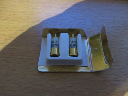
Zwei Mikrowellen-Dioden in Verpackung
1N21B MICROWAVE 1N21B MICROWAVE
in „[V Weitere Sachen, einfach ansehen“ · Markt · · Fotos
-
Datei
DS18B20.asm
accu,0xCC ;Skip_Rom rcall One_Wire_Write ;1 Byte schreiben timer,2 ;2µs delay ldi accu,0xBE ;Vom DS18B20 Ram, die Temperatur auslesen rcall One_Wire_Write ;1 Byte schreiben timer,2 ;2µs delay rcall One_Wire_Read ;1-Wire Byte lesen mov RawLow,accu ;Byte 0 des Scratchpad rcall One_Wire_Read ;1-Wire Byte
-
Datei
rfm12b_rx.c
(ms /= 10; ms > 0; ms--) _delay_ms(10); } int main() { rf12_init(); // ein paar Register setzen (z.B. CLK auf 10MHz) delay_ms(500); // Initialisierung muss manchmal mehrmals gemacht werden, rf12_init(); // da Modul lange braucht delay_ms(1000); rf12_init(); //rf12_setfreq(RF12FREQ(433.92)); // Sende
in „RFM12B Daten auswerten“ · Mikrocontroller und Digitale Elektronik ·
-
PDF
B150XG01.pdf
www.SpecLcd.com Product Functional Specification 15 inch XGA Color TFT LCD Module Model Name : B150XG01 V.2 ( ) Preliminary Specification ) Final Specification Note: This Specification is subject to change without notice. (C) Copyright AU Optronics, Inc. August, 2001 All Rights Reserved. B150XG01
in „15" XGA Display an Computer anschließen“ · Mikrocontroller und Digitale Elektronik ·
-
Datei
sketch_nov08b.ino
int taster=7; //Das Wort „taster" steht jetzt für den Wert 7. int relais1=3; int relais2=2; int Relstat1 = LOW; int Relstat2 = LOW; int tasterstatus = HIGH; int Taststat=LOW; unsigned long time; long previousMillis = 0; // will store last time LED was updated int Zaehler =0 ; long interval = 30000; // interval at which to blink (milliseconds) void setup() //Hier beginnt das Setup. { pinMode(taster, INPUT_PULLUP); //Der Pin mit der LED (Pin 7) ist jetzt ein Eingang INPUT pinMode(relais1, OUTPUT); //Der Pin mit dem Relay1 (Pin 1) ist jetzt ein Ausgang OUTPUT pinMode(relais2, OUTPUT); digitalWrite
in „Arduino UNO an 4fach Relais“ · Mikrocontroller und Digitale Elektronik ·
-
Datei
ds18b20.c
#include "ds18b20.h" #include <util/delay.h> uint8_t therm_reset(uint8_t pin) { uint8_t i; //Pull line low and wait for 480uS THERM_LOW(pin); THERM_OUTPUT_MODE(pin); _delay_us(430); //480 //this must be smaller when
in „_delay_us Funktion in ISR Routine bringt ISR aus dem Tackt.“ · Mikrocontroller und Digitale Elektronik ·
-
Datei
ds18b20.h
#pragma once #include <avr/io.h> #include <stdio.h> #define THERM_PORT PORTD #define THERM_DDR DDRD #define THERM_PIN PIND #define THERM_INPUT_MODE(PIN) THERM_DDR&=~(1<<PIN) #define THERM_OUTPUT_MODE(PIN) THERM_DDR|=(1<<PIN) #define THERM_LOW(PIN) THERM_PORT&=~(1<<PIN) #define THERM_HIGH(PIN) THERM_PORT|=(1<<PIN) #define THERM_CMD_CONVERTTEMP 0x44 #define THERM_CMD_RSCRATCHPAD 0xbe #define THERM_CMD_WSCRATCHPAD 0x4e #define THERM_CMD_CPYSCRATCHPAD 0x48 #define THERM_CMD_RECEEPROM 0xb8 #define THERM_CMD_RPWRSUPPLY 0xb4 #define THERM_CMD_SEARCHROM 0xf0 #define THERM_CMD_READROM 0x33 #define THERM_CMD_MATCHROM
in „_delay_us Funktion in ISR Routine bringt ISR aus dem Tackt.“ · Mikrocontroller und Digitale Elektronik ·
-
Datei
sketch_nov12b.ino
int led = 8; int taster=7; int relais1=3; int relais2=2; int relais3=4; int Relstat1 = LOW; int Relstat2 = LOW; int Relstat3 = LOW; int tasterstatus = HIGH; int Taststat= LOW; // laesst das Programm nicht laufen beim Anstecken unsigned long time; long previousMillis = 0; // will store last time LED was updated int Zaehler =0 ; long interval1 = 3000; // interval at which to blink(milliseconds) long interval2 = 1500; void setup() //Hier beginnt das Setup. { pinMode(taster, INPUT_PULLUP); //Pin7 am Taster ist jetzt ein Eingang beim Drücken pinMode(relais1, OUTPUT); //Pin3 am Relay1 ist jetzt ein
in „Arduino UNO an 4fach Relais“ · Mikrocontroller und Digitale Elektronik ·
-
Datei
sketch_nov15b.ino
/* The circuit: * LCD RS pin to digital pin 12 * LCD Enable pin to digital pin 11 * LCD D4 pin to digital pin 5 * LCD D5 pin to digital pin 4 * LCD D6 pin to digital pin 3 * LCD D7 pin to digital pin 2 * LCD R/W pin to ground * 10K resistor: * ends to +5V and ground * wiper to LCD VO pin (pin 3) */ // include the library code: #include <LiquidCrystal.h> // initialize the library with the numbers of the interface pins LiquidCrystal lcd(12, 11, 5, 4, 3, 2); int sensorPin1 = A0; // select the input pin for the Sensor int sensorPin2 = A1; int sensorValue1 = 0; // variable to store the value coming
in „Arduino UNO an 4fach Relais“ · Mikrocontroller und Digitale Elektronik ·
-
Datei
UNO_R4B.txt
: 0x09 (9 bytes) bDescriptorType : 0x04 (Interface Descriptor) bInterfaceNumber : 0x00 (Interface 0) bAlternateSetting : 0x00 bNumEndpoints : 0x01 (1 Endpoint) bInterfaceClass : 0x02 (Communications and CDC Control) bInterfaceSubClass
in „Arduino UNO R4 in Win10 nicht erkannt“ · Mikrocontroller und Digitale Elektronik ·
-
Datei
sketch_oct06b.ino
selber ;-) Print &cout = Serial; // cout Emulation für "Arme" #include "test.h" char *getA(); char *getB(); void setup() { Serial.begin(9600); cout << F("Start: ") << F(__FILE__) << endl; cout << testStr << endl; cout << getA() << endl; cout << getB() << endl; } void loop() { }
in „Konstanten-Datei in C“ · Mikrocontroller und Digitale Elektronik ·
-
Datei
20221011b-interrupt-Einspeise.ino
Einspeisewechselrichter // https://www.etechnophiles.com/how-to-change-the-pwm-frequency-of-arduino-nano/ // TCCR2B = TCCR2B & B11111000 | B00000001; // for PWM frequency of 31372.55 Hz on D3 & D11 // https://www.arduino.cc/reference/de/language/functions/external-interrupts/attachinterrupt/ int lpumppin = 11; int
-
Datei
20221015b-interrupt-Einspeise.ino
Einspeisewechselrichter // https://www.etechnophiles.com/how-to-change-the-pwm-frequency-of-arduino-nano/ // TCCR2B = TCCR2B & B11111000 | B00000001; // for PWM frequency of 31372.55 Hz on D3 & D11 // https://www.arduino.cc/reference/de/language/functions/external-interrupts/attachinterrupt/ // https://www.mikrocontroller.net
-
Datei
20221021b-interrupt-Einspeise.ino
Einspeisewechselrichter // https://www.etechnophiles.com/how-to-change-the-pwm-frequency-of-arduino-nano/ // TCCR2B = TCCR2B & B11111000 | B00000001; // for PWM frequency of 31372.55 Hz on D3 & D11 // https://www.arduino.cc/reference/de/language/functions/external-interrupts/attachinterrupt/ // https://www.mikrocontroller.net
-
PDF
ENG_DS_1773035_B.pdf
Opposing 25 Watt = HSA25 R10 NHS - Low mounting Feet 50 Watt = HSA50 E - 3% 1ohm J - 5% Inductance B - Flange One 75 Watt = HSA75 (1000 mille ohms) Side etc 1R0 K - 10% C - Flange Two 1K Sides (1000 ohms) 1KO TE Connectivity, TE connectivity (logo) and TE (logo) are trademarks. Other logos, product
in „Berechnug der Waermeabgabe eines Leistungswiderstandes“ · Analoge Elektronik und Schaltungstechnik ·
-
PDF
DT60-6111B.pdf
T L B m N k T s A m E w I w L N O Mid-Range-Distanzsensoren Dx60, DT60 DT60-N111B Mid-Range-Distanzsensoren Dx60, DT60 Typ > DT60-N111B Artikelnr. > 1025844 Auf einen Blick • Messbereich bis 5.300 mm • Analogausgang
in „Laser Distanzsensor mit digitalem Ausgang“ · Mikrocontroller und Digitale Elektronik ·
-
PDF
Bauvorschlag_ADS-B_Antenne.pdf
Und hier der konkrete Bauvorschlag - die ADS-B 1090MHz Bratpfannenantenne: Man nehme eine Bratpfanne (besser nicht die Lieblingspfanne der besten aller Ehefrauen - das gibt mit Sicherheit Ärger). Alternativ geht auch irgendeine Metallscheibe mit
in „Flugzeug-Daten auf 1090 MHz empfangen“ · HF, Funk und Felder ·
-
PDF
Brauchbar_QC12864B.pdf
DSW Data hold time H Pin: DB0-DB7 25 — — nS Data delay time (read) t Pin: DB0-DB7 — — 125 nS DDR 8.2b AC Characteristics (VDD=5V, Ta=25℃) Serial Mode Interface 深 圳 市 亚 斌 电 子 有 限 公 司 SHENZHEN YABIN ELECTRONICS CO.,LTD ------------------------------------------------------------------------------------
-
PDF
US8235003B2.pdf
US8235003B2.pdf
in „Digital Egg Monitor“ · Mikrocontroller und Digitale Elektronik ·
-
PDF
US7336348B2.pdf
US7336348B2.pdf
in „Digital Egg Monitor“ · Mikrocontroller und Digitale Elektronik ·
-
 Bild
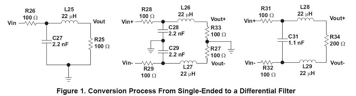
Schaltpläne zur Umwandlung eines Single-Ended- in einen Differenzfilter
R26 100 Ω L25 22 µH Vout C27 2.2 nF R25 100 Ω Vin R28 100 Ω C28 2.2 nF C29 2.2 nF L27 22 µH R29 100 Ω Vin- R27 100 Ω R33 100 Ω Vout+ Vout- L26 22 µH Vin+ R31 100 Ω C31 1.1 nF L28 22 µH R34 200 Ω R32 100 Ω L29 22 µH Vin- Vout+ Vout- Figure 1. Conversion Process From Single-Ended to a Differential Filter
in „Differenzielle Filter (LTSPICE)“ · Analoge Elektronik und Schaltungstechnik · · Schaltpläne
-
PDF
Ferroxcube_4B1.pdf
FERROXCUBE DATA SHEET 4B1 Material specification Supersedes data of September 2004 2008 Sep 01 Ferroxcube Material specification 4B1 4B1 SPECIFICATIONS Medium permeability NiZn ferrite for use in wideband EMI-suppression (30
in „Ringmischer selber wickeln, welches Kernmaterial“ · HF, Funk und Felder ·
-
PDF
DE102006020301B4.pdf
(19) *DE102006020301B420140731* (10) DE 10 2006 020 301 B4 2014.07.31 (12) Patentschrift (21) Aktenzeichen: 10 2006 020 301.1 (51) Int Cl.: (22) Anmeldetag: 03.05.2006 G01R 27/26 (2006.01) (43) Offenlegungstag: 09.11.2006
in „Laufzeit eines Komparators“ · Analoge Elektronik und Schaltungstechnik ·
-
PDF
MOT-AE-B-...DE.pdf
Flachstecker Länge [mm] 4,5 4,5 4,5 Breite [mm] 2,0 2,0 2,0 Stärke [mm] 0,3 0,3 0,3 4 / 9 www.igus.de MOT-AE-B_DE_201504#1 DC-Motoren MOT-AE-B . . . / MOT-DC-… Technische Daten Maße Typ B1 B2 B3 D1 D2 D3 L1 L2 L3 L4 [mm] [mm] [mm] Ø [mm] Ø [mm] Ø [mm] [mm] [mm] [mm] ±0,3 ±0,2 ±0,1 -0,013 ±0,025 [mm] ±1 ±1 MOT-AE-B
in „Zuckende DC-Motoren bei Ansteuerung mit H-Brücke/PWM und Arduino UNO“ · Mikrocontroller und Digitale Elektronik ·
-
PDF
LED_Dimmer_2b.pdf
LED_Dimmer_2b.pdf
in „LED-Dimmer pfeift“ · Analoge Elektronik und Schaltungstechnik ·
-
PDF

