-
PDF
G5177B_Kopie.pdf
.0YC WWW 00YC .W WWW WW W. 0.OM .W Ver: 0.1 WW.1 Y.OM Jul 31, 2013 W WW.0 1 W OM.W .00. OM.W G5177B G lo b a l M ix eWWW-.0Y. M.W T e c h n o lo g y VOUT to GND . . . . . . .T1ermal Resistance of Junction to Ambient (θ LX to GND .0Y . .W. . W .SO0-8 (.T) . . . . . . . . . . . . . . . . . . . . . .
in „Boost Converter IC Ausgangsstrom festlegen“ · Analoge Elektronik und Schaltungstechnik ·
-
PDF
BTA_16-600B.pdf
20 10 S(cm²) 00 4 8 12 16 20 24 28 32 36 40 PACKAGE MECHANICAL DATA TO-220AB (Plastic) DIMENSIONS B C REF. Millimeters Inches b2 Min. Typ. Max. Min. Typ. Max. L A 15.20 15.90 0.598 0.625 a1 3.75 0.147 I F a2 13.00 14.00 0.511 0.551 A B 10.00 10.40 0.393 0.409 b1 0.61 0.88 0.024 0.034 l4 b2 1.23 1.32
in „BTA 16-600B Triacs“ · Markt ·
-
PDF
UP6281B8.pdf
uP6281 12V MOSFET Drivers with Output Disable for Single Phase Synchronous-Rectified Buck Converter General Description Features TheuP6281isadual,highvoltageMOSFETdriveroptimized All-In-OneSynchronousBuckDrivers rectified buck converter. Each driver is capable of driving aotstrapped High-SideDriver 5000pFloadwith30nstransitiontime.Thisdevicecombined AdaptiveAnti-Shoot-Through Protection withuPImulti-phasebuckPWMcontrollerformsacomplete Circuitry corevoltageregulatorforadvancedmicro-processors. 1 PWM Signal Generates both Drivers TheuP6281featuresadaptiveanti-shoot-throughprotection OutputDisable
in „Am3 Mainboard Vcore instabil wenn kalt“ · PC Hard- und Software ·
-
PDF
REX0128128B-datasheet.pdf
REX0128128B OLED Graphic 128x128 dots 36.98±0.2 2.05±0.2 35.98(PLZ) 0.70 30.00 AA 1.10 Cover Glass . l R6 r L A 0 o 3( 0 1 c 2 3 5 0 9 4 6 3 3 3 Pull tape n n I n n 5 IC , R6 1 NBBBVCDDCVV Silicon s Tape 20.00±0.2
in „OLED-Display SPI Psoc4“ · Mikrocontroller und Digitale Elektronik ·
-
PDF
b8_handbuch_1205.pdf
14 1 64 1 - - -/- -/- - - 3 12 - 11 - Name Pins Prog EEPRM TMR Capt PWM UART SSP CAN USB ADC IO- [kB] [B] -ure CMP /SPI I2C Pins 16F610 14 1 - 2 - - -/- -/- - - - 12 16F616 14 3 - 3 1 1 -/- -/- - - 8 12 16F627 18 1 128 3 1 1 1/- -/- - - - 16 16F628 18 3 128 3 1 1 1/- -/- - - - 16 16F630 14 1 128 2 -
in „PIC16f628 programmieren“ · Mikrocontroller und Digitale Elektronik ·
-
PDF
Oppermann_B104_1.pdf
Oppermann_B104_1.pdf
in „Oppermann Bausatz B 104“ · Analoge Elektronik und Schaltungstechnik ·
-
PDF
Oppermann_B104_2.pdf
Oppermann_B104_2.pdf
in „Oppermann Bausatz B 104“ · Analoge Elektronik und Schaltungstechnik ·
-
PDF
3B0_IBTR.pdf
Produkt - Preise / Bestellungen hier Seite als RS232 <=> D/A 16 Bit Konverter Modul (Prod. Nr. #3B0) Merkmale: Vollständige galvanischer Trennung zwischen: Spannungsversorgung <-> RS232 <-> D/A Für Hutschienemontage T 90 x H 75 x B 23 (mm) RS232 von 300 bps bis 750000 bps ! RS232: ±15 kV Human Body
in „Suche Converter RS232 -> DAC 5V 1mA“ · Mikrocontroller und Digitale Elektronik ·
-
PDF
TXC_Crystals_9b.pdf
and Cable Modem. r z > RoHS Compliant / Pb Free C r y t a Electrical Specifications l s Item / Type 9B Frequency Range 3.2 ~ 90 MHz Frequency Tolerance (at 25 ºC) ± 30 ppm, or specify Frequency Stability Over Operating Temperature Range ± 30 ppm (- 20 ~ +70 ºC), or specify Operating Temperature Range
in „Quarz mit großem Ziehbereich (für VCXO)“ · Analoge Elektronik und Schaltungstechnik ·
-
PDF
treiber_l293B.pdf
0.100 e3 17.78 0.700 F 7.1 0.280 i 5.1 0.201 L 3.3 0.130 Z 1.27 0.050 a I b1 L b B e E Z e3 D P . 16 9 1 D F P 1 8 10/12 L293B - L293E POWERDIP (16+2+2) PACKAGE MECHANICAL DATA Dimensions Millimeters Inches Min. Typ. Max. Min. Typ. Max. a1 0.51 0.020 B 0.85 1.4 0.033 0.055 b 0.5 0.020 b1 0.38 0.5 0.015 0.020 T D 24.8 0.976 W 2 E 8.8 0.346 D e 2.54 0.100 e3 22.86 0.900 F 7.1 0.280 i 5.1 0.201 L 3.3 0.130 Z 1.27 0.050 a I L b1 b B e E Z e3 Z D S E 20 11 0 I F M P 1 10 11/12 L293B - L293E
in „Aufbau der Treiberbausteine von bipolaren Schrittmotor“ · Mechanik, Gehäuse, Werkzeug ·
-
PDF
P82B715.pdf
notes AN255, ÒIC/SMBus repeaters, hubs and expandersÓand AN10710, ÒFeatures and applications of the P82B715 I C-bus extend.rÓ 4.1 Ordering options Table 2. Ordering options Type number Topside mark Temperature range P82B715PN P82B715PN −40 °C to +85 °C P82B715TD P82B715 −40 °C to +85 °C P82B715_8 © NXP
in „Arduino I2C Probleme Sonsoren werden manchmal nicht gefunden“ · Mikrocontroller und Digitale Elektronik ·
-
PDF
notes_82b96.pdf
output to some new and different bus at A'. This is transmitted over some path to an equal buffer at B. The low input at B' drives the SDA line at B to low as required. But the buffer at B is sensing the SDA bus and will then output a low at B*. This is transmitted back to the first buffer as an input
in „I²C galvanisch trennen“ · Mikrocontroller und Digitale Elektronik ·
-
PDF
BabyController_B328.pdf
B-328 Robot Controller - Bezug Robotikhardware.de Schaltplan Der Schaltplan gilt sowohl für das Orangutan B328 als auch dessen kleinere Varianten! Seite 9 von 23 Anleitung zum Baby Orangutan B-328 Robot
in „Baby Orangutan b-328“ · Mikrocontroller und Digitale Elektronik ·
-
PDF
WS2812B_preliminary.pdf
o d e D a ta re fre sh c y c le 1 D a ta re fre sh c y c le 2 se c o n d se c o n d D 1 first 2 4 b 2 4 b ith ird 2 4 b it first 2 4 b2 4 b itth ird 2 4 b it s2 4 b ith ird 2 4 b it s2 4 b itth ird 2 4 b it D 2 th ird 2 4 b it th ird 2 4 b it D 3 D 4 WS2812B Intelligent control LED integrated light
in „[Mitbestellung] SMD5050 RGB-LED mit integriertem 8-bit PWM Controller“ · Markt ·
-
PDF
Steuerplatine_Rev06b.pdf
X X X X X C1 A 3n3 3n3 3n3 A 100n n 2 n 3 n 4 n 5 4 1GND1 5 1ND1 6 1ND1C 7 1GND1 1 C2 C73C8 TG12864B-05 GND1 A A A A A A A Belegung von Pin19/20 variiert! +5V/1 P P P P P P P +5V/1 V GND1 S R2 2 1 1 1 1 1 1 1 1 1 19 8 7 6 5 4 3 2 1 C9 R3 E S 2 1 7 6 5 4 3 2 1 0 100n E E S S B B B B B B B BN WS GND1
in „Grafik-LCD 64128-LED“ · Mikrocontroller und Digitale Elektronik ·
-
PDF
Ampire_AC-162B.pdf
Ampire_AC-162B.pdf
in „[V] 2x16 LCD (HD44780) mit / ohne Hintergrundbeleuchtung“ · Markt ·
-
PDF
MKP_B32651_658.pdf
-pin 27.5 0.8 B32654 A1 2-pin 37.5 1.0 B32656A/J A1 2-pin 37.5 1.0 B32656T A2 4-pin 37.5 1.2 B32656G B1 4-pin 52.5 1.2 B32658G B1 (Dimensions in mm) Dimensional drawings 2-pin versions Drawing A1 B32651 B32652 B32653
in „Schleichender Leistungsverlust an Siemens Induktionskochfeld“ · Haus & Smart Home ·
-
PDF
-
PDF
-
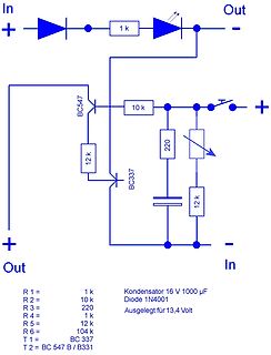
 Bild
Schaltplan einer Spannungsregelung
1N4001 R 3 = 220 R 4 = 1 k Ausgelegt für 13,4 Volt R 5 = 12 k R 6 = 104 T 1 = BC 337 T 2 = BC 547 B / B331
in „Gold-Cap < 1F laden“ · Analoge Elektronik und Schaltungstechnik · · Schaltpläne
-
PDF
cd4017b-mil.pdf
CD4017BM Samples CD4017BNSR ACTIVE SO NS 16 2000 RoHS & Green NIPDAU Level-1-260C-UNLIM -55 to 125 CD4017B Samples CD4017BPW ACTIVE TSSOP PW 16 90 RoHS & Green NIPDAU Level-1-260C-UNLIM -55 to 125 CM017B Samples CD4017BPWR ACTIVE TSSOP PW 16 2000 RoHS & Green NIPDAU Level-1-260C-UNLIM -55 to 125 CM017B Samples
in „SPS erweitern für 32 Temperatureingänge“ · Analoge Elektronik und Schaltungstechnik ·
-
 Bild
Flexible Leiterplattenstreifen auf Millimeterpapier
TEA1102T__b.jpg
in „[V] 15St Vintage NiCd/NiMh LadeIC Philips TEA1102T SMD (10€)“ · Markt · · Platinenfotos

-
PDF
DS_D3402-B.pdf
Data Sheet FUJITSU Mainboard D3402-B µATX Data Sheet FUJITSU Mainboard D3402-B µATX Extended Lifecycle Series Powered by the Intel® Q170 Express Chipset supporting DDR4 2133 SDRAM Memory and 6 generation Intel® Core TM i3 / i5 / i7 Processors
in „[V] Industrial uATX Mainboard+CPU+Kühler+16GB Ram“ · Markt ·
-
PDF
0900766b815369be.pdf
TX PIN5 RX PIN4 RX Mode 0 1 TX PIN5 RX PIN4 TX Mode 1 0 ANT w nSEL 1 w 16 w . GND R s SDI 2 F o 15 L u l O t Vcc R o SDO 3 A n 14 . o 4 . 13 SCLK RX_SWITCH k TX_SWITCH 5 12 RESET DIO0 6 11 DIO5 DIO1 7 10 DIO4 DIO2 8 9 DIO3 19.95 +/- 0.5mm 17.45 2.5 2.5 3 2 8 . 1 2 7 w 1 . L o R ti A s o k m 5 - 5 3 2 PCB Layout R 0.45 1.00 2.0 19.95 +/- 0.5mm 2.5 2 6.35 1.93mm 8 1 16.29mm m 0 + 1 2 0.6mm 2.88 1.00 2.0 SDI XTAL S SDO SCLK P LNA I RF nSEL RF MATCHING ANT RF Switch CIRCUIT IC PA DIO 0 - 5 BDetectoroltage RX SWITCH TX SWITCH SX1272 Datasheet
in „Arduino und Funkmodul rf-lora-868-so“ · Mikrocontroller und Digitale Elektronik ·
-
PDF
TEM-U2400B-.pdf
Discharge 9 output Figure 1. Block diagram TELEFUNKEN Semiconductors 1 (15) Rev.A2, 21-Nov-96 U2400B ~ V 1 = V r W s 0 V e 8 1 . S ) 1 k = T M 2 R . y N R e k 1 t R 0 B D5 6 V 3 V 8 3 4 5 .2 Y A1 A R1 R R 1 D B D B 6 G 5 k W W W T1 1 8 R 0 3 k 4 k k R 1 Y 1 R 1 R 0 R 5. D B 9 W 1 W R 0 m W k 2 . 5 m
in „NI-CD Batterielader mit U2400B“ · Analoge Elektronik und Schaltungstechnik ·
-
PDF
WS2812B-MINI.pdf
WS2812B-Mini Intelligent external control LED Integrated light source Features and Benefits The IC’s control circuit and the LED share the same power supply. Control circuit and RGB chip are integrated in
in „Indirekte Beleuchtung mit ca. 30m LED Streifen“ · Analoge Elektronik und Schaltungstechnik ·
-
PDF
0900766b815875fa.pdf
EN ENGLISH RS Stock number 734-7056 Specifications: MECHANICAL LIFE: 30,000 make-and-break cycles. CONTACT RESISTANCE: 10mΩ max. initial@ 2-4VDC 100mA for both silver and gold plated contacts INSULATION RESISTANCE: 1000MΩmin. DIELECTRIC STRENGTH: 1,000Vrms min. @ sea level. OPERATING TEMPERATURE: -30°C to 85°C. CASE: Dially phthalate (DAP) UL94v-0) ACTUATOR: Brass, chrome plated Bushing: Brass, nickel plated Housing: Stainless steel CONTACT/TERMINAL: Brass, Silver or gold plated Switch Support: Brass, tin plated RoHS: 2002/95/EC RS, Professionally Approved Products, gives you professional quality
in „Kippschalter AUS/EIN/EIN“ · Markt ·
-
PDF
oled_weh001602b.pdf
oled_weh001602b.pdf
in „6800 Interface an XMC“ · Mikrocontroller und Digitale Elektronik ·
-
PDF
0900766b8002938f.pdf
0900766b8002938f.pdf
in „[V] 26St. "alte" NiCD / NiMH LadeChip Philips TEA1101 DIP16 (10€)“ · Markt ·
-
PDF
U2010B-1.PDF
U2010B Phase Control Circuit for Current Feedback Description The U2010B is designed as a phase-control circuit in output. Motor control with load-current feedback and bipolar technology. It enables load-current
in „Wie funktioniert die Drehzahlregelung beim Allstrommotor“ · Analoge Elektronik und Schaltungstechnik ·
-
PDF
Quarzfilter_Rev2b.pdf
für die Induktivität L (somit auch für C ) kr kr der Abschlusskreise für die gewünschte Bandbreite B 3dbberechnen : L L kr = A ⋅ Q ( 5 ) 2 ⋅ kr Hinweis: “A“ entspricht “β “O und “b“ entspricht “β“ in Kautters Artikel [2]. Siehe dort Seite 49. ** Gl. (4) ist folgendermaßen abgeleitet : b = 2 ⋅R res β
in „Schmalbandiges LC-Filter, praktischer Aufbau“ · HF, Funk und Felder ·
-
PDF
B340-341-342.pdf
B340-341-342.pdf
in „Unterschied DDR-Typ B340/B341/B342“ · Analoge Elektronik und Schaltungstechnik ·
-
PDF
DS18B20.pdf
-55°C to +125°C 3 TO-92 (2000 Piece) 18B20 DS18B20+T&R -55°C to +125°C 3 TO-92 (2000 Piece) 18B20 DS18B20-SL/T&R -55°C to +125°C 3 TO-92 (2000 Piece)* 18B20 DS18B20-SL+T&R -55°C to +125°C 3 TO-92 (2000 Piece)* 18B20 DS18B20U -55°C to +125°C 8 FSOP 18B20 DS18B20U+ -55°C to +125°C 8 FSOP 18B20 DS18B20U/T&R -55°C to +125°C 8 FSOP (3000 Piece) 18B20 DS18B20U+T&R -55°C to +125°C 8 FSOP (3000 Piece) 18B20 DS18B20Z -55°C to +125°C 8 SO DS18B20 DS18B20Z+
in „DS18B20 Sensor“ · Mikrocontroller und Digitale Elektronik ·
-
PDF
Siemens_B4110_TOC.pdf
aufweist, • trotz intakter Batterien nicht mehr aribeitet, • längere Zeit ungünstigen Vernältnissen (z.B. Lagerung außertlalb der grenzen ohne Anpassung an das Raumklima, Betauung, o. ä.oder, • schwerenTransportbeansprucbunqen(z.B.Fallaus großer Höheohne s· ," Beschädigung, o.ä.) ausgesetzt war, • bzw.
in „Reparaturversuch: Norma Unilap 701 X“ · Analoge Elektronik und Schaltungstechnik ·
-
PDF
Q3B_Betriebsanleitung.pdf
Info-Schnittstelle 62056-61) Datenprotokoll SML 1.03 DE–9 Betriebsanleitung Easy-16817-DE Abmessungen: Q3B x10xx ohne Zusatzklemmen Abb. 3: Maßblatt (60-Ampere-Ausführung mit 6,5-mm-Klemmen) DE–10 info@easymeter.com, www.easymeter.com EasyMeter Q3B Abmessungen: Q3B x20xx und Q3B x30xx ohne Zusatzklemmen Abb
in „Arduino Nano Easymeter Q3BA auslesen und Shuntregler“ · Mikrocontroller und Digitale Elektronik ·
-
PDF
M51951B_Datasheet.pdf
M51951B_Datasheet.pdf
in „Drop-In-Replacement für Mitsubishi M51951B?“ · Mikrocontroller und Digitale Elektronik ·
-
PDF
-
PDF
steuerung_2021-B_Cu.pdf
0. 1V gnureuet S OSL
in „Arduino brennt durch“ · Mikrocontroller und Digitale Elektronik ·
-
PDF
-
PDF
MC14504B-D.PDF
MC14504B Hex Level Shifter for TTL to CMOS or CMOS to CMOS The MC14504B is a hex non−inverting level shifter using CMOS technology. The level shifter will shift a TTL signal to CMOS logic levels for any CMOS
-
PDF
cd4098b__2_.pdf
& no Sb/Br) CD4098BPW ACTIVE TSSOP PW 16 90 Green (RoHS NIPDAU Level-1-260C-UNLIM -55 to 125 CM098B & no Sb/Br) CD4098BPWR ACTIVE TSSOP PW 16 2000 Green (RoHS NIPDAU Level-1-260C-UNLIM -55 to 125 CM098B & no Sb/Br) JM38510/17504BEA ACTIVE CDIP J 16 1 TBD SNPB N / A for Pkg Type -55 to 125 JM38510/
in „Max. Pulsverlängerung mit CD4098“ · Mikrocontroller und Digitale Elektronik ·
-
PDF
MC14538B-D.PDF
Semiconductor Components Industries, LLC, 2014 1 Publication Order Number: July, 2014 − Rev. 11 MC14538B/D MC14538B PIN ASSIGNMENT BLOCK DIAGRAM C VSS 1 16 VDD X RX VDD CX/RXA 2 15 V SS 1 2 RESET A 3 14 CX/RXB A 4 AA 4 13 RESET B Q1 6 B BA 5 12 AB 5 Q1 7 RESET QA 6 11 BB Q 7 10 Q 3 A B V 8 9 Q SS B CX R
in „Max. Pulsverlängerung mit CD4098“ · Mikrocontroller und Digitale Elektronik ·
-
PDF
Quarzfilter_Rev2b.pdf
für die Induktivität L (somit auch für C ) kr kr der Abschlusskreise für die gewünschte Bandbreite B 3dbberechnen : L L kr = A ⋅ Q ( 5 ) 2 ⋅ kr Hinweis: “A“ entspricht “β “O und “b“ entspricht “β“ in Kautters Artikel [2]. Siehe dort Seite 49. ** Gl. (4) ist folgendermaßen abgeleitet : b = 2 ⋅R res β
in „Messen von Quarz-Parametern - Probleme“ · HF, Funk und Felder ·
-
PDF
Relais-g6b.pdf
relay Model Minimum ordering unit G6B-1114P(-FD)-US-P6B G6B-1174P(-FD)-US-P6B P6B-04P G6B-1177P(-FD)-ND-US-P6B G6BU-1114P-US-P6B 20 pcs G6BK-1114P-US-P6B P6B-06P G6B-2114P-US-P6B G6B-2214P-US-P6B P6B-26P G6B-2014P-US-P6B Removal Tool P6B-Y1
in „Snubber für stromloses ausschalten eines Transformators notwendig?“ · Analoge Elektronik und Schaltungstechnik ·
-
PDF
EP0743754B1.pdf
Europäisches Patentamt (19) European Patent Office *EP000743754B1* Office européen des brevets (11) EP 0 743 754 B1 (12) FASCICULE DE BREVET EUROPEEN (45) Date de publication et mention (51) Int Cl. H03K 17/725, H05B 41/04 de la délivrance du brevet: 17.01.2001 Bulletin
in „Schnellstarter für Leuchtstofföhren - welche taugen was?“ · Haus & Smart Home ·
-
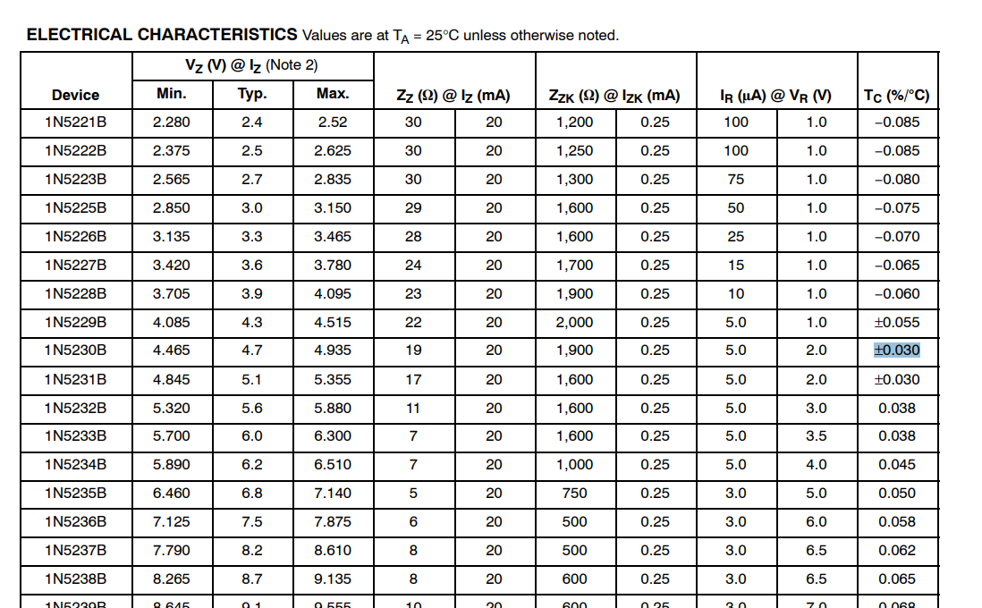
 Bild
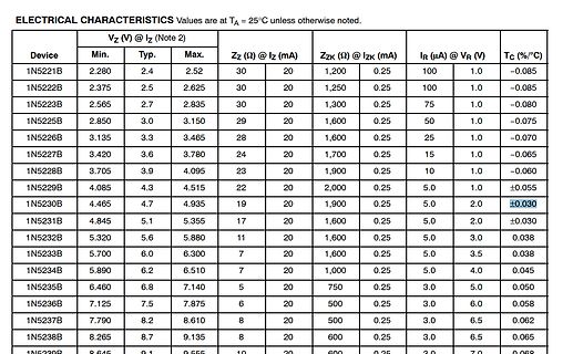
Tabelle mit elektrischen Eigenschaften von Zener-Dioden
50 1.0 -0.075 1N5226B 3.135 3.3 3.465 28 20 1,600 0.25 25 1.0 -0.070 1N5227B 3.420 3.6 3.780 24 20 1,700 0.25 15 1.0 -0.065 1N5228B 3.705 3.9 4.095 23 20 1,900 0.25 10 1.0 -0.060 1N5229B 4.085 4.3 4.515 22 20 2,000 0.25 5.0 1.0 ±0.055 1N5230B 4.465 4.7 4.935 19 20 1,900 0.25 5.0 2.0 ±0.030 1N5231B 4
in „Lineares Netzteil“ · Analoge Elektronik und Schaltungstechnik · · Screenshots
-
 Bild

-
 Bild
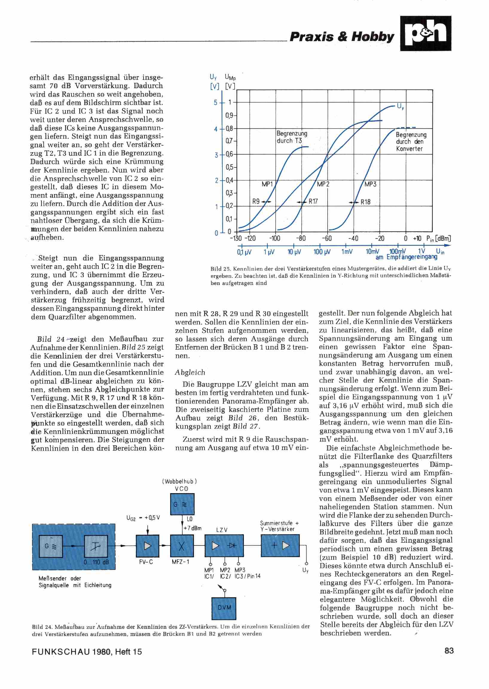
Zeitschriftenseite mit Diagramm und Schaltungsaufbau
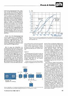
Praxis & Hobby, UT, UMp, U, MP1, R9, R17, MP2, MP3, Begrenzung durch TC3, Begrenzung durch Konverter, VCO, U02, +0,5 V, LZ V, MFZ-1, FV-C, DVM, FUNKSCHAU 1980, Heft 15
in „DDR- Oszilloskop OG2-30/ OG2-31 Restauration“ · Analoge Elektronik und Schaltungstechnik · · Screenshots
-
PDF
Keysight-54601B-Datasheet.pdf
Bandwidth HP 54600B and HP 54601B dc to 100 MHz 3 dB ac coupled, 10 Hz to 100 MHz –3 dB HP 54602B dc to 100 MHz 3 dB (1, 2, & 5 mV/div) dc to 150 MHz 3 dB (channels 1 & 2) dc to 250 MHz 3 dB (channels 3 & 4) ac coupled, 10 Hz to 150 MHz –3 dB (channels 1 & 2) HP 54603B dc to 60 MHz 3 dB ac coupled, 10 Hz to 60 MHz Rise time 3.5 ns (calculated, HP 54600B & HP 54601B) <2.33 ns (calculated, channels 1 & 2, HP 54602B) <1.4 ns (calculated, channels
in „[V] HP 54601B Vierkanal Oszilloskop 100 MHz / 20 MS“ · Markt ·
-
 Bild
Ein Einbaubackofen mit geöffneter Tür
CIRCOTHERM Heissluft 160°C 20:06 EFF
in „Wer repariert meine Platine?“ · Platinen · · Fotos