-
Datei
config.c
/* Konfiguration für das Testboard mit STM32F302RBT6 */ #include "StdTypes.h" #include "STM32F302xB.h" #include "startup.h" #include "config.h" /**************** symbolische Port-Pin Eigenschaften **************************/ /* Pro Port gibt
in „Welcher Timer ist für die Dauer eines Ticks im SysTick verantwortlich?“ · Mikrocontroller und Digitale Elektronik ·
-
Datei
bla.c
/*****************************************************************/ {int k; uint32_t val; // aus stm32f4xx_spi.h /* SPI_InitTypeDef; I2S_InitTypeDef; void I2S_Init(SPI_TypeDef* SPIx, I2S_InitTypeDef* I2S_InitStruct); void I2S_StructInit(I2S_InitTypeDef* I2S_InitStruct); void I2S_Cmd(SPI_TypeDef* SPIx
in „MEMS mic mit I2S am STM32F405“ · Mikrocontroller und Digitale Elektronik ·
-
Datei
tools.c
/* -------------- System Include Files ------------------- */ #include "stm32f10x_conf.h" #include "system_stm32f10x.h" /* -------------- Standard Include Files ---------------- */ #include <stdbool.h> #include <stdint.h> #include <stdio.h> #include <stdlib.h> /* -----------
in „STM32F1xx: Wie GOL am "Leben" halten?“ · Mikrocontroller und Digitale Elektronik ·
-
Datei
config.c
/* Konfiguration für das Testboard mit STM32F302RBT6 */ #include "StdTypes.h" #include "STM32F302xB.h" #include "startup.h" #include "config.h" /**************** symbolische Port-Pin Eigenschaften **************************/ /* Pro Port gibt
in „stm32f103 hse clock“ · Mikrocontroller und Digitale Elektronik ·
-
Datei
sysinit.c
********************** */ /* -------------- System Include Files ------------------- */ #include "stm32f10x_conf.h" #include "system_stm32f10x.h" /* -------------- Standard Include Files ----------------- */ #include <stdbool.h> #include <stdint.h> #include <stdio.h> #include <stdlib.h> /* ----------
in „Timer Interrupt STM32F103“ · Mikrocontroller und Digitale Elektronik ·
-
Datei
SK6812.cpp
------------------------------ Arduino library to control SK6812 RGB Led strips using the Arduino STM32 LibMaple core ----------------------------------------------------------------------------------------------- Note. This library has only been tested on the SK6812 LED. It may not work with the older
in „STM32 Bluepill -> SK6812 (auf Basis von WS2812B Lib)“ · Projekte & Code ·
-
Datei
simple.s
@ Simple(s) Beispiel @ GPIO register map is similiar to STM32F4 chips. @ -> register boundary address pp. 65 in DM00031020.pdf .equ BIT0, 0x00000001 .equ BIT1, 0x00000002 .equ BIT2, 0x00000004 .equ BIT3, 0x00000008 .equ BIT4, 0x00000010 .equ BIT5, 0x00000020
in „STM32CubeIDE Debug View, Threads, Breakpoints“ · Mikrocontroller und Digitale Elektronik ·
-
Datei
MyFunctions.c
Geraet: ******************************************************************************/ #include <stm32f10x_conf.h> #include "MyFunctions.h" #include "EXTI_HW_Init.h" #include <stm32f10x_spi.h> #include <stdio.h> #include "stm32f10x_usart.h" // globale Variablen // statische Variablen uint8_t s_Rx =0
in „UART Problem beim senden“ · Mikrocontroller und Digitale Elektronik ·
-
Bild
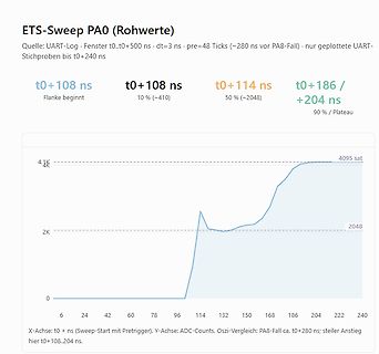
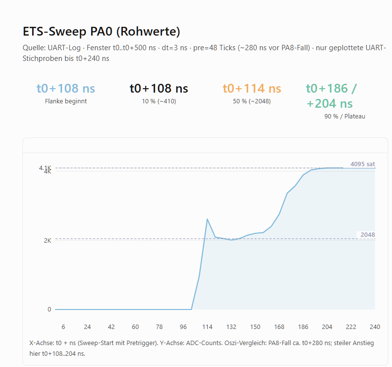
Diagramm eines ETS-Sweep PA0 Messverlaufs
ETS-Sweep PA0 (Rohwerte) Quelle: UART-Log · Fenster t0..t0+500 ns · dt=3 ns · pre=48 Ticks (~280 ns vor PA8-Fall) · nur geplottete UART-Stichproben bis t0+240 ns t0+108 ns Flanke beginnt t0+108 ns 10 % (~410) t0+114 ns 50 % (~2048) t0+186 / +204 ns 90 % / Plateau 4.1K 2K 0 6 24 42 60 78 96 114 132 150 168 186 204 222 240 X-Achse: t0 + ns (Sweep-Start mit Pretrigger). Y-Achse: ADC-Counts. Oszi-Vergleich: PA8-Fall ca. t0+280 ns; steiler Anstieg hier t0+108...204 ns. 4095 2048
in „Auflösung der Abtastung eines periodischen Signals mit ADC“ · Mikrocontroller und Digitale Elektronik · · Oszi-Bilder
-
Datei
usbd_cdc_vcp.c
------------------------------------------*/ /** * @brief VCP_Init * Initializes the Media on the STM32 * @param None * @retval Result of the opeartion (USBD_OK in all cases) */ static uint16_t VCP_Init(void) { NVIC_InitTypeDef NVIC_InitStructure; /* EVAL_COM1 default configuration */ /* EVAL_COM1 configured
in „STM32F2xx - USB_OTG_FS“ · Mikrocontroller und Digitale Elektronik ·
-
Datei
main.c
#include "stm32f10x.h" #include <stdbool.h> #include <stdio.h> #include "main.h" // ---------------------------------------------------------------------------- /* * * RAM Bank of 5 23LC1024 SPI memory chips testing
in „SPI-RAM-Bank an STM32F0-Discovery - write, kein read“ · Mikrocontroller und Digitale Elektronik ·
-
Datei
serial.c
/* serielle Kommunikation für STM32F103C8T6 */ #include "StdTypes.h" #include "STM32F103all.h" #include "startup.h" #include "config.h" #include "serial.h" /* Funktionsprinzip: Der eigentliche Datenverkehr über die diversen UART's wird
in „Sende/Empfangsvorgang mittels nur 1St. µC“ · Mikrocontroller und Digitale Elektronik ·
-
Datei
i2c_referenz.c
#include <stdio.h> #include "stm32f10x_gpio.h" #include "stm32f10x_rcc.h" #include "i2c.h" #include "debug.h" static void I2C1_InitI2C(void); static void I2C2_InitI2C(void); static int8_t I2C1_Timeout(I2C_TypeDef* I2Cx, int8_t val);
in „STM32F103C8T6 Blue Pill - SSD1306 - u8g2“ · Mikrocontroller und Digitale Elektronik ·
-
Datei
audio.c
#include "Audio.h" #include "stm32f4xx_conf.h" #include "stm32f4xx.h" #include <stdlib.h> static void WriteRegister(uint8_t address, uint8_t value); static void StartAudioDMAAndRequestBuffers(); static void StopAudioDMA(); static AudioCallbackFunction
in „STM32F4Discovery Audio "Störgeräusche"“ · Mikrocontroller und Digitale Elektronik ·
-
Datei
i2c.c
#include <stdio.h> #include "stm32f10x_gpio.h" #include "stm32f10x_rcc.h" #include "i2c.h" #include "debug.h" static void I2C1_InitI2C(void); static void I2C2_InitI2C(void); static int8_t I2C1_Timeout(I2C_TypeDef* I2Cx, int8_t val);
in „STm32Fxxx: I2C Hardware Experten gesucht“ · Mikrocontroller und Digitale Elektronik ·
-
Datei
usart_nrf3.h
#ifndef __USART_NRF3_H #define __USART_NRF3_H #ifdef DTU3PRO #include "stm32f4xx.h" #define UsartNrf USART3 #else #include "stm32f10x.h" #endif #include <math.h> #include <stdlib.h> #include <stdio.h> #include <string.h> #include <stdbool.h> #include <string.h> #include "rtc.h
in „Wechselrichter Hoymiles HM-xxxx 2,4 GhZ Nordic Protokoll?“ · Mikrocontroller und Digitale Elektronik ·
-
Datei
ili9341.c
_t num_samples = 0U; // change SPI clock to 2MHz, max rate supported by XPT2046 // TODO: based on STM32G4, which is clocked at 170MHz. support other chips. //MODIFY_REG(lcd->spi_hal->Instance->CR1, SPI_CR1_BR, SPI_BAUDRATEPRESCALER_128); ili9341_spi_touch_select(lcd); while ((itpPressed == ili9341_touch_pressed
in „STM32U575 und ILI9341 SPI DMA Problem“ · Mikrocontroller und Digitale Elektronik ·
-
PDF
emw3165.pdf
on-board flash. 4. Use SWD (Pin 25&26) instead of JTAG to debug/download firmware. 5. Please refer to STM32F411xE datasheet about alternate function mapping. 4 3 Electrical Parameters 3.1 Operating conditions EMW3165 enters an unstable condition whenever the input voltage dips below the minimum value of
in „EMW3165 - Der ESP8266 Killer ?“ · Mikrocontroller und Digitale Elektronik ·
-
Datei
main.c
#include "main.h" //#include "RGB565_480x272.h" uint16_t RGB565_480x272[130560]; /** @addtogroup STM32F7xx_HAL_Examples * @{ */ /** @addtogroup LTDC_Display_1Layer * @{ */ /* Private typedef -----------------------------------------------------------*/ /* Private define -----------------------------
in „STM32F7 Discovery Board“ · Mikrocontroller und Digitale Elektronik ·
-
Datei
main.c
----------------------------------------------------------------------------------------------- * STM32: *--------------------------------------------------------------------------------------------------------------------------------------------------- */ #elif defined(ARM_STM32) uint32_t SysCtlClockGet
in „IRMP-Anwendung“ · Mikrocontroller und Digitale Elektronik ·
-
Datei
main.c
/* Includes ------------------------------------------------------------------*/ #include "stm32f10x.h" #include "stm32f10x_conf.h" #define GPIOB_LED GPIO_Pin_2 #define GPIOC_BZZ GPIO_Pin_13 #define UH 0x0004 #define UL 0x0001 #define VH 0x0040 #define VL 0x0010 #define WH 0x0400 #define WL 0x0100
in „STM32F1 Brushless Motor Steuerung“ · Mikrocontroller und Digitale Elektronik ·
-
Datei
cc-fft-out.txt
leo@cb:~/Projekte/STM32F103C8-gen-board/philips-vfd$ ./cc-fft.sh + ./cc-fft.sh Using built-in specs. COLLECT_GCC=arm-none-eabi-gcc Target: arm-none-eabi Configured with: ../src/configure --build=x86_64-linux-gnu --prefix=
in „STM32 Arduino“ · Mikrocontroller und Digitale Elektronik ·
-
Datei
HCT595.c
*********************** */ /* -------------- System Include Files ------------------ */ #include "stm32f10x_conf.h" #include "system_stm32f10x.h" /* -------------- Standard Include Files ---------------- */ #include <stdbool.h> #include <stdint.h> #include <stdio.h> #include <stdlib.h> /* -----------
in „EmBitz Debugging Problem mit STM32F103“ · Mikrocontroller und Digitale Elektronik ·
-
PDF
project.pdf
P P P P P P P P P P P P P P P P P V V C33 100nF 6 7 8 9 0 1 2 3 4 5 6 7 8 9 0 1 2 3 4 5 6 7 8 9 0 STM32F407VGT6 +5V +5V P2 +5V P3 2 2 2 2 3 3 3 3 3 3 3 3 3 3 4 4 4 4 4 4 4 4 4 4 5 M1OUTA 1 M2OUTA 1 R21 2 R23 2 +3.3V 3.3k 3.3k GND C38 P10 ENC1B 3 8 ENC2B 3 8 +3.3V 6 k 0 7 X X +3.3V 1 N 4 C 4 C R 1 5 R
in „Schaltplan so richtig? STM32F407VG“ · Mikrocontroller und Digitale Elektronik ·
-
PDF
project.pdf
P P P P P P P P P P P P P P P P P V V C33 100nF 6 7 8 9 0 1 2 3 4 5 6 7 8 9 0 1 2 3 4 5 6 7 8 9 0 STM32F407VGT6 +5V +5V P2 +5V P3 2 2 2 2 3 3 3 3 3 3 3 3 3 3 4 4 4 4 4 4 4 4 4 4 5 M1OUTA 1 M2OUTA 1 R21 2 R23 2 +3.3V 3.3k 3.3k GND C38 P10 ENC1B 3 8 ENC2B 3 8 +3.3V 6 k 0 7 X X +3.3V 1 N 4 C 4 C R 1 5 R
in „Schaltplan so richtig? STM32F407VG“ · Mikrocontroller und Digitale Elektronik ·
-
PDF
STM32F103C8T6_Mikrocontroller_Schematics.pdf
in „Arduino Blue Pill & CAN mit SN65HVD230“ · Mikrocontroller und Digitale Elektronik ·
-
PDF
STM32F103C8T6_Mikrocontroller_Schematics.pdf
in „Arduino Blue Pill & CAN mit SN65HVD230“ · Mikrocontroller und Digitale Elektronik ·
-
Datei
main.c
#include "stm32f0xx.h" #include <stdbool.h> #include <stdio.h> #include "main.h" // ---------------------------------------------------------------------------- /* * * RAM Bank of 5 23LC1024 SPI memory chips testing
in „SPI-RAM-Bank an STM32F0-Discovery - write, kein read“ · Mikrocontroller und Digitale Elektronik ·
-
Datei
main.c
#include "stm32f0xx.h" #include <stdbool.h> #include <stdio.h> #include "main.h" // ---------------------------------------------------------------------------- /* * * RAM Bank of 5 23LC1024 SPI memory chips testing
in „SPI-RAM-Bank an STM32F0-Discovery - write, kein read“ · Mikrocontroller und Digitale Elektronik ·
-
Datei
simple_server.c
; plen = fill_tcp_data_p(buf, plen, PSTR("<center><p>")); plen = fill_tcp_data_p(buf, plen, "<h1> STM32 WEBSERVER </h1>"); plen = fill_tcp_data_p(buf, plen, "<h2> STM32F103ZET6 </h2>"); plen = fill_tcp_data_p(buf, plen, "<table border>" ); plen = fill_tcp_data_p(buf, plen, "<thead>"); plen = fill_tcp_data_p
in „Webpage Webserver“ · Mikrocontroller und Digitale Elektronik ·
-
Datei
F2_messung.c
/* Vergleich reziproke Frequenzmessung mit STM32H750 F2_ergebnis aus Mittelwerten nach 1 s Messzeit und ref_f als Ergebnis aus Regressionsberechnung Michael Nowak 2019-12-17 www.mino-elektronik.de */ #include <stdio.h> #include "stm32h7xx.h" #include
in „lineare Regression bei reziprokem Frequenzzähler wirkungslos?“ · Mikrocontroller und Digitale Elektronik ·
-
Datei
main.c
-------------------------------------------------------------*/ #include "main.h" /** @addtogroup STM32F4xx_HAL_Examples * @{ */ /** @addtogroup TIM_ParallelSynchro * @{ */ /* Private typedef -----------------------------------------------------------*/ /* Private define -----------------------------
in „STM32 Timer synchronisieren“ · Mikrocontroller und Digitale Elektronik ·
-
Datei
tools.c
/* -------------- System Include Files ------------------- */ #include "stm32f10x_conf.h" #include "system_stm32f10x.h" /* -------------- Standard Include Files ---------------- */ #include <stdbool.h> #include <stdint.h> #include <stdio.h> #include <stdlib.h> /* -----------
in „Matrix indizierbar machen?“ · Mikrocontroller und Digitale Elektronik ·
-
Datei
readme.txt
ich gefunden (und sogar verfuegbar) hatte war im Jahr 2016 ein STM8S103F3P6. Stand 2023 waere ein STM32F030f4 bei sehr deutlich besseren Leistungsdaten preiswerter. Hier jedoch die Version fuer STM8S103. ###################################################################################### Serielle Schnittstelle
-
PDF
basic_interpreter.pdf
den ich gefunden (und sogar verfügbar) hatte war im Jahr 2016 ein STM8S103F3P6. Stand 2023 wäre ein STM32F030f4 bei sehr deutlich besseren Leistungsdaten preiswerter. Hier jedoch jetzt die finale Version für einen STM8S103. Da der Speicherplatz des Mikrocontrollers nun fast komplet ausgenutzt ist, wird
-
PDF
Bulb_Ohm.pdf
on GND. To check that MCP4725-DAC-module works well we convert its output voltage with an ADC of STM32F103 and transmit the result via USB-Black-Pill-jack to a terminal program. STM32CubeMX 4.26.1 creates the basic code of our program, whereby the version 4.26.1 is not important. 1.: Setup and check

in „I2C STM32F103“ · Mikrocontroller und Digitale Elektronik ·
-
Bild
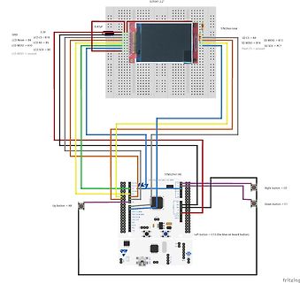
Fritzing-Schaltplan mit STM32F411RE und LCD-Display
> PC7 Flash CS > unused Up button > A8 Down button > C1 C13 > Left button (blue on board button) STM32F411RE
in „Signalplotter mit STM32, LCD und SD Karte - ähnlich einem Scope“ · Projekte & Code · · Screenshots
-
Bild
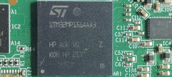
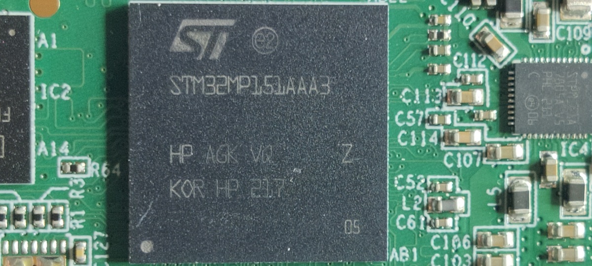
Makroaufnahme eines STM32MP15LAAA3 Mikrocontrollers auf Leiterplatte
ST STM32MP15LAAA3 HP AGK VR Z KOR HP 217 05 A1 IC2 A14 R33 R64 C112 C113 C57 C114 C107 C52 L2 C61 C166 C103 IC4
in „free2move eProWallbox Reverse Engineering (OEM Bitron; ISO 15118 (!), Linux)“ · Fahrzeugelektronik · · Platinenfotos
-
Bild
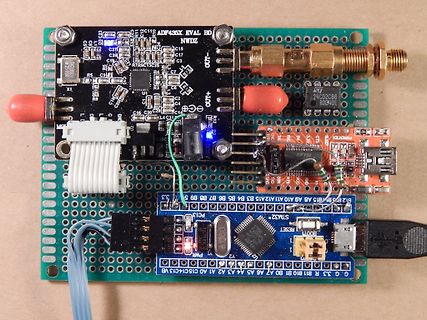
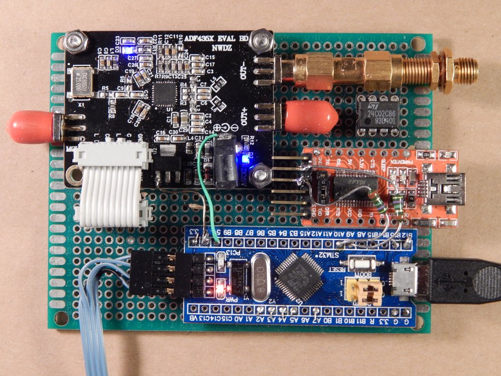
Aufbau mit ADF435X Evaluation Board und STM32 Board
ADF435X EVAL BD NWDZ C27 C26 C15 C17 OUT- OUT+ 24C02C86 93C401 STM32 PWR BOOT
in „ADF4351 Steuerung mit BluePill - reloaded“ · HF, Funk und Felder · · Platinenfotos
-
Bild
STM32F4DISCOVERY TFT Display mit Text und Zahlen
STM32F4DISCOVERY 3.2 TFT Display Text und Graphic Controller SSD1289 1234567 OK!
in „Einstieg TFT“ · Mikrocontroller und Digitale Elektronik · · Fotos
-
Bild
Schaltplan STM32F103 Blue Pill mit TFT-Modul
1.8 SPI 128x160 TFT Module ST7735R Controller VCC GND CS SDA SCK LED +3,3V 10k 10k 10k 38 Vcc PB7 PB6 PA8 PA1 PA7 PA5 23 PC14 25 PA0 24 PC15 GND 40 left up down right
in „Game CodedColor für die STM32F103 Bluepill“ · Projekte & Code · · Schaltpläne
-
Bild
Fehlermeldung beim Verbindungsaufbau zu STM32W1xx Gerät
Error Can not connect to target! If you're trying to connect to an STM32W1xx device, please select Normal or HotPlug mode from Target-> Settings menu. If you're trying to connect to a low frequency application, please select a lower SWD Frequency mode from Target-> Settings
in „STM32F103C6T6A Lässt sich nicht programmieren“ · Mikrocontroller und Digitale Elektronik · · Screenshots
-
Bild
Blockschaltbild der Spannungsversorgung eines STM32L433RBT6 Mikrocontrollers
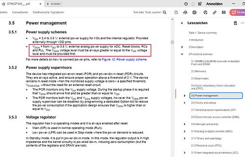
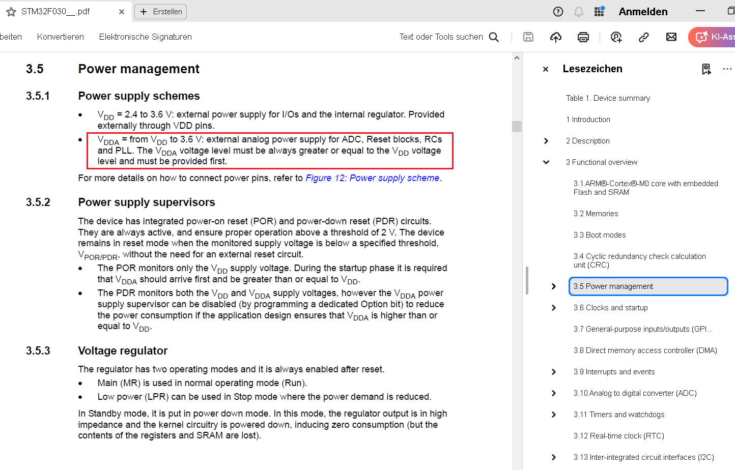
STM32L433RBT6_C1... V_DDA domain A/D converters, Comparators, D/A converters, Operational amplifiers, Voltage reference buffer. V_LCD LCD. V_DDUSB domain USB transceivers. V_SS. V_DD domain Reset block,
in „STM32f030F4 eigene PCB“ · Mikrocontroller und Digitale Elektronik · · Screenshots
-
Bild
Schaltplan eines STM32G031G8Ux Mikrocontrollers
U2 STM32G031G8Ux, BTN1, BTN3, BTN2, LED1, LED2, PA8, PA9, PA10, SWIO, SWCLK, PA0 bis PA15, VSS, VDD, PF2-NRST, PC6, PC14-OSC32_IN, PC15-OSC32_OUT, RFM69 CS, RESET, SCK, MISO, MOSI, IRQ, C6, C7, C8, C9, C10,
in „STM32G031G8 Grundbeschaltung / keine Verbindung über SWD“ · Mikrocontroller und Digitale Elektronik · · Schaltpläne
-
Bild
Tabelle der allgemeinen Betriebsbedingungen STM32H7Sxx8
Electrical characteristics STM32H7Sxx8 Table 26. General operating conditions (continued) Symbol Parameter Operating conditions Min Typ Max Unit fCPU CPU clock frequency VOS low - - 400 VOS high - - 600(8) fACLK AXI clock frequency
in „STM32H7Sx: Maximale Frequenz?“ · Mikrocontroller und Digitale Elektronik · · Screenshots
-
Bild
Schaltplan eines HF-Teils mit STM32WLE5CCU6
GND L5 9.1nH C80 100pF C76 3.6pF L13 47nH C77 6.8pF C75 3.6pF C79 47pF U36 3.9nH GND GND GND U37 STM32WLE5CCU6 PB3 VSSMPS PB4 VLXSMPS PB5 VDDSMPS PB6 VFBSMPS PB7 PA15 PA0 PA14 PA1 A13 VDDA PA2 PC15-OSC32_OUT IN PA3 PC14-OSC32_OUT PA4 VDDA PA5 PC13 PA6 PA12 PA7 PA13 PA8 PA12 PB1 PB2 NRST PH3-BOOT0 RFI
in „868MHz Impedanzmatching - Fragen zum Matching-vorgehen“ · HF, Funk und Felder · · Schaltpläne
-
Bild
Schaltplan eines HF-Teils mit STM32WLE5CCU6
GND L14 3.9nH U22 BWU.FL-IPEX1 RF_CTL1 C83 6.2pF GND R57 100ohm C66 33pF SKY13323-378LF VCTL2 INPUT VCTL1 OUTPUT1 U35 C29 100pF C23 100pF R56 100ohm C67 33pF GND L5 15nH C80 100pF C73 2.8pF C76 3.6pF C74 2.5pF C77 1.6pF C75 4.3pF C85 4.7pF L10 10nH C79 47nF C78 47nF U36 RF_I_N RF_O_LP RF_HO RF_PA VR_PA VDDPA PB0-VDD_TCXO VDD RF_I_N RF_O_LP RF_HO RF_PA VR_PA VDDPA PB0-VDD_TCXO VDD RF_I_N RF_O_LP RF_HO RF_PA VR_PA VDDPA PB0-VDD_TCXO VDD RF_I_N RF_O_LP RF_HO RF_PA VR_PA VDDPA PB0-VDD_TCXO VDD RF_I_N RF_O_LP RF_HO RF_PA VR_PA VDDPA PB0-VDD_TCXO VDD RF_I_N RF_O_LP RF_HO RF_PA VR_PA VDDPA PB0-VDD_TCXO
in „868MHz Impedanzmatching - Fragen zum Matching-vorgehen“ · HF, Funk und Felder · · Schaltpläne
-
Bild
Elektronik-Aufbau mit STM32 Nucleo, RS485-Konverter und Sensor
STM32-Nucleo-Board PC-Anschluss USB-RS485-Konverter Eckstein-MAX485 Tel:485-A Blue 485-B Sensor
in „Differentiell-Taster für RS485?“ · Analoge Elektronik und Schaltungstechnik · · Fotos
-
Bild
Pinbelegung STM32F303RETx LQFP64 Mikrocontroller
PA2, PA1, PA0, VDDA, VSSA, PC3, PC2, PC1, PC0, NRST, PF0-, PF1-, OSC_IN, PC15, PC14, Button, VBAT, STM32F303RETx, LQFP64
in „Bootloader Mode STM32F303“ · Mikrocontroller und Digitale Elektronik · · Screenshots
-
Bild
Schaltplan eines Mikrocontroller-Designs mit STM32L431CBT6
GND OSC_IN, OSC_OUT, BOOT0, VDD, VSS, VODA, VDOB, RST, PA0 bis PA15, PB0 bis PB15, SWDIO, SWCLK, STM32L431CBT6, J5, R15 47, R16 10k, R17 120, C24 100n, Rain-Sensor, Controller, KiCad E.D.A. 6.0.5
in „Wetterstation - Low Power Design“ · Platinen · · Schaltpläne