-
PDF
Aim_TTi_QL_Series_II_Service_Manual_48511-1740.pdf
SM0805 47PG CER NPO C11, C14, C16 23414-3226 CAP SM1210 22UK 16V CER C1-3 23461-0015 CAP SM0805 10NK 50V CER X7R C6, C15, C22 23461-0020 CAP SM0805 100NZ 50V CER Y5V C10, C17-21, C23-25, C28-30, C33,C34 23461-0040 CAP SM0805 1N0K 50V CER X7R C8 23461-0050 CAP SM0805 22NJ 50V CER X7R C26 23461-0070 CAP SM0805 4N7J 50V CER X7R C7,C36 23461-0080 CAP SM0805 47NK 50V CER X7R C27 23461-0200 CAP SM0805 2N2J 50V CER X7R C9 23461-0310 CAP SM1206 1UK 25V CER X7R C32 23559-5220 CAP SM 22U 35V AL ELEC C13 25377-1000 TRAN SM
in „wegen Aim TTi Netzteil Qualität“ · Analoge Elektronik und Schaltungstechnik ·
-
PDF
MAX306-MAX307.pdf
A1 0 NO2-NO15 6 A2 A3 MAX306 NO16 +10V M tr < 20ns EN COM V LOGIC +3V f < 20ns A GND V- OUT INPUT 50% 50Ω 35pF 0V X 300Ω -15V VNO1 3 +15V 90% 0 SWITCH 7 V+ OUTPUT A0 NO1B ±10V VOUT 0V A1 90% A2 NO1A-NO8A V NO16 NO8B +10V tTRANS TRANS EN COMB ON GNDMAX307 VOUT V- 35pF 50Ω 300Ω -15V Figure 2. Transition Time +15V V+ EN NO1 -5V A0 NO2-NO16 A1 MAX306 A2 A3 COM tr < 20ns VOUT LOGIC +3V f < 20ns 50Ω GND V- 35pF INPUT 50% 1kΩ 0V ON(EN) OFF(EN) -15V 0V +15V 10% SWITCH EN V+ NO1B -5V OUTPUT NO1A-NO8A 90% A0 NO2B-NO8B, VOUT COMA A1 MAX307 A2 COMB VOUT 50Ω GND V- 35pF 1kΩ -15V Figure 3. Enable Switching
in „Welche Spannung kann der Multiplexer MAX307 schalten?“ · Analoge Elektronik und Schaltungstechnik ·
-
PDF
BST-BMP180-DS000-07.pdf
Temperature measurement included 2 - I C interface - Fully calibrated - Pb-free, halogen-free and RoHS compliant, - MSL 1 New features comparison BMP180 BMP085 Smaller package height 0.93mm 1.2mm Faster conversion time (standard mode each) 7.5ms (max.) 7.5ms (max) 2 Faster IC data transfer max. 3.4MHz
in „Suche Projektpartner für Kalmanfilter-Implementierung“ · Digitale Signalverarbeitung / DSP / Machine Learning ·
-
PDF
MX29F040C__5V__4Mb__v2.2.pdf
of program and erase operation completion PACKAGE • 32-Pin PLCC • 32-Pin TSOP • All devices are RoHS Compliant P/N:PM1201 REV. 2.2, DEC. 04, 2012 1 M X 2 9 F 0 4 0 C Contents FEATURES.....................................................................................................................
-
PDF
Optokoppler.pdf
Collector Power Dissiption vs. Ambient Temperatute vs. Ambient Temperature 60 )200 W ( ) 50 c A n150 F 40 t t a e i u 30 i100 c r r w w 20 P o r 50 F 10 c l C 0 0 -55 0 25 50 75 100 125 -55 0 25 50 75 100 125 o o Ambient temperature Ta ( C) Ambient temperature Ta ( C) Fig.3 Collector-emitter
in „Encoderauswertung, Verständnisfrage und Schaltplan“ · Mikrocontroller und Digitale Elektronik ·
-
PDF
Any-Grid_PSW-H_DE-manual_2020-07-29-2.pdf
24V LCD-Anzeige Modell) < 44,4 / < 22,2V 0 bis 24% 44,4 ~ 46,4V / 22,2 ~ 23,2V 25 bis 49 % Last > 50% 46,4 ~ 48,4V / 23,2 ~ 24,2V 50 bis 74 % > 48,4V / > 24,2V 75 bis 100 % < 45,4 / 22,7V 0 bis 24% 45,4 ~ 47,4V / 22,7 ~ 23,7V 25 bis 49 % Last < 50% 47,4 ~ 49,4V / 23,7 ~ 24,7V 50 bis 74 % > 49,4V / >
in „(V) Hybrid-Wechselrichter Phocos PSW-H-5kW/48V“ · Markt ·
-
PDF
Metrz_Anschlussdose.pdf
Einbau waagrecht 50 mm, ohne Trennschale 1308895021-I Montagehalter für Anschlussdosen Tragschienenbefestigung - Einbau waagrecht 50 mm, mit Trennschale 1308895040-I Montagehalter für Anschlussdosen T-Nut-Befestigung -
-
PDF
smp04.pdf
Typ Max Units Linearity Error 0.01 % Buffer Offset Voltage V OS VIN = 6 V –10 2.5 +10 mV Hold Step V HS VIN = 6 V, TA= +25°C to +85°C 2.5 4 mV VIN = 6 V, TA= –40°C 5 mV Droop Rate V/ t V = 6 V, T = +25°C 2 25 mV/s 1 IN A Output Source Curre1t ISOURCE VIN = 6 V 1.2 mA Output Sink Current ISINK VIN = 6 V
in „Power Supply Bypassing - wie ist es richtig??“ · Analoge Elektronik und Schaltungstechnik ·
-
PDF
smp04.pdf
Typ Max Units Linearity Error 0.01 % Buffer Offset Voltage V OS VIN = 6 V –10 2.5 +10 mV Hold Step V HS VIN = 6 V, TA= +25°C to +85°C 2.5 4 mV VIN = 6 V, TA= –40°C 5 mV Droop Rate V/ t V = 6 V, T = +25°C 2 25 mV/s 1 IN A Output Source Curre1t ISOURCE VIN = 6 V 1.2 mA Output Sink Current ISINK VIN = 6 V
in „Sample-and-Hold-Verstärker - wie richtig beschalten??“ · Analoge Elektronik und Schaltungstechnik ·
-
PDF
smp04.pdf
Typ Max Units Linearity Error 0.01 % Buffer Offset Voltage V OS VIN = 6 V –10 2.5 +10 mV Hold Step V HS VIN = 6 V, TA= +25°C to +85°C 2.5 4 mV VIN = 6 V, TA= –40°C 5 mV Droop Rate V/ t V = 6 V, T = +25°C 2 25 mV/s 1 IN A Output Source Curre1t ISOURCE VIN = 6 V 1.2 mA Output Sink Current ISINK VIN = 6 V
in „Umgang mit Hold-Step bei Sample-and-Hold-Versärkern“ · Mikrocontroller und Digitale Elektronik ·
-
PDF
RAC03-SCR_277.pdf
/ 1minute 80 Isolation Resistance 1GΩ min ( e 60 Short Circuit Protection Continuous,Auto Restart P50 Safe Operating Area Over Current Limit 105% - 150% u 40 u Over Voltage Protection (Zener diode clamp) 130%-160% O 20 Operating Temperature Range natural convection, without derating -25°C to +75°C 0
in „Suche Trafo - So klein wie möglich“ · Analoge Elektronik und Schaltungstechnik ·
-
PDF
9b-14516.pdf
Fundamental 3rd Overtone 3.2 ~ 3.686 MHz 200 Ω Max. 27 ~ 30 MHz 100 Ω Max. 3.686 ~ 5 MHz 150 Ω Max. 30 ~ 50 MHz 80 Ω Max. 5 ~ 10 MHz 80 Ω Max. 50 ~ 90 MHz 60 Ω Max. 10 ~ 14 MHz 40 Ω Max. 14 ~ 30 MHz 30 Ω Max. Dimensions Units:mm Remark : Specification subject to change without prior notice. Please confirm
-
PDF
Viahay__BZX84.pdf
model: > 8 kV, machine model: > 800 V PRIMARY CHARACTERISTICS PARAMETER VALUE UNIT • Base P/N-E3 - RoHS-compliant, commercial grade VZrange nom. 2.4 to 75 V • Base P/N-HE3 - RoHS-compliant, AEC-Q101 qualified Test currenZTI 2; 5 mA • Material categorization: for definitions of compliance VZspecification
in „Spannungsteiler: niedrigere Ausgangsspannung bei 90 °C“ · Analoge Elektronik und Schaltungstechnik ·
-
PDF
Arcam-FMJ-P7.pdf
3BGBU8D Diode Bridge Rectifier GBU8D Plastic Package 8A 200V C103 2C410 Capacitor SM 1206 X7R Ceramic 50V 10% 100N C104 2C210 Capacitor SM 1206 NPO Ceramic 50V 5% 1N0 C200 2C410 Capacitor SM 1206 X7R Ceramic 50V 10% 100N C201 2C410 Capacitor SM 1206 X7R Ceramic 50V 10% 100N C202 2C410 Capacitor SM 1206
in „Bandbreite von analogen Audioschaltungen“ · Analoge Elektronik und Schaltungstechnik ·
-
PDF
Arcam-FMJ-P7.pdf
3BGBU8D Diode Bridge Rectifier GBU8D Plastic Package 8A 200V C103 2C410 Capacitor SM 1206 X7R Ceramic 50V 10% 100N C104 2C210 Capacitor SM 1206 NPO Ceramic 50V 5% 1N0 C200 2C410 Capacitor SM 1206 X7R Ceramic 50V 10% 100N C201 2C410 Capacitor SM 1206 X7R Ceramic 50V 10% 100N C202 2C410 Capacitor SM 1206
in „Bester Audio OPV“ · Analoge Elektronik und Schaltungstechnik ·
-
PDF
008-0256-0_F.pdf
Compatible • Fundamental and 3 RD Overtone Crystals • Frequency Range 1.5 – 160 MHz • Frequency Stability, ±50 ppm Standard (±25 ppm and ±20 ppm available) • +3.3Vdc or +5.0Vdc Operation • Operating Temperature to –40°C to +85°C • Output Enable Standard • Tape & Reel Packaging • RoHS/Green Compliant (6/6) DESCRIPTION
-
PDF
EZPack_XL__2260mAh.pdf
Rating: 8.4Wh Charging Method: Constant Current + Constant Voltage Max. Charge Voltage [V]: 4.20(±50mV) Max. Continuous Charge Current: 1080mA Rec. Charge Cut Off: by current 50mA or timer 4h Max. Continuous Discharge Current: 2000mA Rec. Discharge Cut Off: 3V Internal Impedance: approx. 110mΩ Exp.
in „Li-Ion Akku Lade-IC gesucht“ · Mikrocontroller und Digitale Elektronik ·
-
PDF
BME1205S-02A.pdf
temperature: -40°C to +90°C contact: SMD housing color: black packageing: tray IP rating: n.a. ESD conform RoHs conform: yes remark: no steps 2. Electrical and acoustical specification DC resistance [Ω] 45 ± 5 Impedance [Ω] 2400Hz, sine wave, 60 µA 80 Resonance frequency [Hz] 2400 Rated voltage [V] V op 5 Operating voltage [V] 4 - 7 SPL [dBA]: at 5Vop square wave, 2400Hz, 10cm distance, 50% duty 90 - 98 cycle Current consumtion [mA] at 5Vop square wave, 2400Hz, 50% duty cycle 40 Remark: Frequency curve GREWUS dimensions without tolerance: ± 0.3 scale: Designed by: Ralf Hinnerichs 02.07.2009
in „Spannungsänderungen mit Optokoppler erkennen?“ · Mikrocontroller und Digitale Elektronik ·
-
PDF
delta_smp43.pdf
Protection .Universal input SMP-43EP-7 A D P S-4 3E P -13 ENVIRONMENTAL o o .Operation Temperature: 10 C ~ 50 C ambient .Storage Temperature: -30 C ~ + 85 Co . MTBF: > 50,000 hours ELECTRICAL SPECIFICATION MECHANICAL DRAWING Input .Input Voltage: 90~264Vac PE .Frequency: 47~63Hz .Input Current: 1.8A, low line
in „[V] Schaltnetzteil 5V/11A“ · Markt ·
-
PDF
pcm1796.pdf
n 0.001 R o f = 192 kHz i r S m 120 a n l f = 48 kHz D t S T − f = 96 kHz 118 + S D T 0.0001 116 4.50 4.75 5.00 5.25 5.50 4.50 4.75 5.00 5.25 5.50 V CC − Supply Voltage − V V CC − Supply Voltage − V Figure 11 Figure 12 SIGNAL-to-NOISE RATIO CHANNEL SEPARATION vs vs SUPPLY VOLTAGE SUPPLY VOLTAGE 126 122
in „Audio Signal verdoppeln“ · Analoge Elektronik und Schaltungstechnik ·
-
PDF
307.pdf
Insulation resistance1) 100M: Min. (DC 500V) Dielectric strength1) Between open contact : AC 1000V, 50/60Hz 1 min. Between contact and coil : AC 2500V, 50/60Hz 1 min Operating extremes 10 Дʳ50Hz , amplitude 1.0 mm Vibration resistance Damage limits 10 Д 50Hz , amplitude 1.0 mm Operating extremes 10G Shock
in „Trotec TTK 75E Luftentfeuchter, Kompressor läuft im Off Zustand“ · Haus & Smart Home ·
-
PDF
TECHFUSE.pdf
Min. Max. Min. Min. nSMD005 3.00 3.50 1.50 1.80 0.60 1.10 0.15 0.10 nSMD010 3.00 3.50 1.50 1.80 0.60 1.10 0.15 0.10 nSMD012 3.00 3.50 1.50 1.80 0.60 1.10 0.15 0.10 nSMD020 3.00 3.50 1.50 1.80 0.40 0.90 0.15 0.10 nSMD025 3.00 3.50 1.50 1.80 0.40 0.90 0.15 0.10 nSMD035 3.00 3.50 1.50 1.80 0.40 0.90 0.15 0.10 nSMD050 3.00 3.50 1.50 1.80 0.35 0.85 0.15 0.10 nSMD050-13.2V 3.00 3.50 1.50 1.80 0.35 0.85 0.15 0.10 nSMD075 3.00 3.50 1.50 1.80 0.40 0.90 0.15 0.10 nSMD100 3.00 3.50 1.50
-
PDF
TMC262_datasheet.pdf
for motor and driver. Cheaper motor - does the job. 0,9 Efficiency with coolStep 0,8 Efficiency with 50% torque reserve 0,7 0,6 0,5 Efficiency 0,4 0,3 0,2 0,1 0 0 50 100 150 200 250 300 350 Velocity [RPM] Figure 5.1 Energy efficiency example with coolStep Figure 5.1 shows the efficiency gain of a 42mm
in „Wärmeentwicklung Mosfet“ · Mikrocontroller und Digitale Elektronik ·
-
PDF
23810294.pdf
4.26 0.50 3706 3866 35 0.6530 3069 2.22 - 4.14 0.54 3001 3137 40 0.5324 2502 2.33 - 4.03 0.58 2444 2560 45 0.4365 2052 2.43 - 3.92 0.62 2002 2102 50 0.3599 1691 2.53 - 3.81 0.66 1649 1734 55 0.2982 1402 2.62 -
-
PDF
tps63020.pdf
current limit V IN= VINA= 3.6 V, A = 25°C 3500 4000 4500 mA High side switch on resistance V = V = 3.6 V 50 mΩ IN INA Low side switch on resistance V IN= VINA= 3.6 V 50 mΩ Quiescent VIN and VINA IOUT = 0 mA, VEN= V IN= VINA= 3.6 25 50 μA q current V, VOUT V OUT = 3.3 V 5 10 μA TPS63021 FB input impedance V
in „ESP32-H2 will nicht schlafen“ · Mikrocontroller und Digitale Elektronik ·
-
PDF
AVR506.pdf
Load Resistance (ESR) Vendor Type (SMD/HOLE) [±ppm] Capacitance [pF] [kΩ] EPSON C-002RX HOLE 20 6 50 EPSON C-004R HOLE 20 6 50 EPSON C-005R HOLE 20 6 50 EPSON MC-30A SMD 20 6 50 EPSON MC-306 SMD 20 6 50 EPSON MC-405 SMD 20 6 50 EPSON MC-406 SMD 20 6 50 GOLLEDGE GWX HOLE 5 6 35 GOLLEDGE GSWX-26 SMD 10
in „Bascom atmega169P“ · Mikrocontroller und Digitale Elektronik ·
-
PDF
datasheet.pdf
-Out+ PI-4975-022108 Figure 50a. Layout Considerations for TOPSwitch-HX Using E-Package and Operating at 66 kHz. Isolation Barrier Y1- Input Filter Capacitor C6 R7 C7 Capacitor T1 C16 R12 R6 J1 HS1 D5 C4 + D8 HV H52 Output - Rectifier
in „Verzweifelt: Wie Widerstände und Kapazitäten eines Sperrwandler IC´s auslegen?“ · Analoge Elektronik und Schaltungstechnik ·
-
PDF
KEM_PMR209_DB-EN.pdf
cUL Peak Pulse Voltage 1,000 V Series Resistance The series resistance is defined at 1 kHz for RC ≥ 50 µs and at 100 kHz for RC < 50 µs Minimum Values Between Terminals Insulation Resistance C ≤ 0.33 µF ≥ 3,000 MΩ C > 0.33 µF ≥ 1,000 MΩ • µF Maximum 12 A repetitive. Maximum 20 A peak for occasional Pulse
in „Bauteilsuche Entstörkondensator“ · Analoge Elektronik und Schaltungstechnik ·
-
Datei
thermo3.asm
ENABLE MOVWF PORTB BCF PORTC, 7 CALL DELAY RETURN DELAY: MOVWF TEMPA MOVLW 0x00A ; MULTIPLIKATOR ZU 50us VARDELAY: MOVWF VAL0 DEC0: MOVLW 0x0A ; VERZ 50us MOVWF VAL1 DEC1: DECFSZ VAL1,1 GOTO DEC1 DECFSZ VAL0,1 GOTO DEC0 MOVF TEMPA, W RETURN MEGDELAY: MOVLW 0x64 ; 64 MULTIPLIKATOR ZU 50us MOVWF VAL8 DEC9: MOVLW 0xF7 ; F7 VERZ 50us MOVWF VAL9 DEC8: DECFSZ VAL9,1 GOTO DEC8 DECFSZ VAL8,1 GOTO DEC9 RETURN ENDE: END
in „ad-wert ausgabe an lcd“ · Mikrocontroller und Digitale Elektronik ·
-
PDF
APT1608QBC-D-65281.pdf
20mA Ȝpeak Blue 460 - nm Dominant WavelengthʳI F 20mA Ȝdom [1] Blue 465 - nm Spectral Bandwidth at 50% ĭ REL MAX ʳF = 20mA ǻȜ ▯ Blue 25 - nm Capacitance C Blue 100 -ʳ pF Forward VoltageʳI = 20mA V [2] Blue 3.3 4 V F F Reverse Current (VR= 5V) IR Blue - 50 uA Temperature Coefficient ofpeak I = 20mA, -
-
 Bild
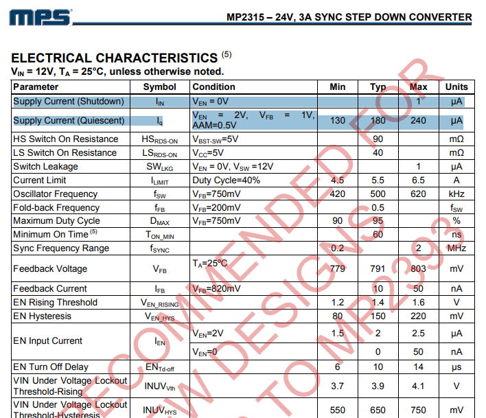
Tabelle der elektrischen Eigenschaften eines Step Down Converters
| | | 1 | µA Supply Current (Quiescent) | Iq | VEN = 2V, VFB = 1V, AAM=0.5V | 130 | 180 | 240 | µA HS Switch On Resistance | HRS-ON | VBST-SW=5V | | 90 | | mΩ LS Switch On Resistance | LSR-ON | VCC=5V | | 40 | | mΩ Switch Leakage | SWLK | VEN = 0V, VSW = 12V | | | 1 | µA Current Limit | ILIMIT | Duty
in „ESP32 3,3V auf 1,5V reduzieren“ · Analoge Elektronik und Schaltungstechnik · · Screenshots
-
 Bild
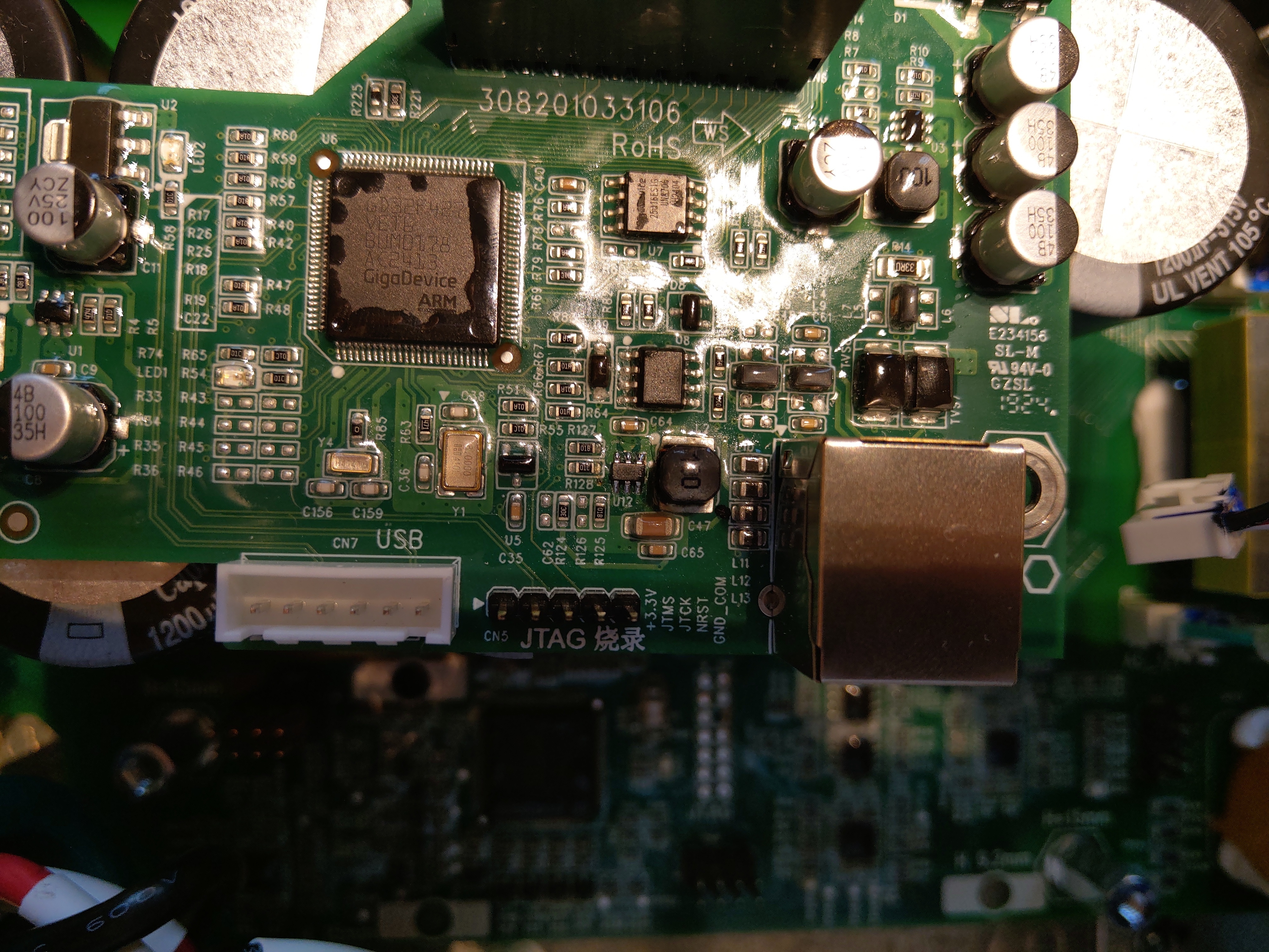
Nahaufnahme einer Leiterplatte mit GigaDevice ARM Mikrocontroller
308201033106 RoHS U2 GigaDevice ARM U1 U4 U5 CN7 USB CN5 JTAG CN6 GND_COM R60 R59 R58 R57 R56 R55 R54 R53 R52 R51 R50 R48 R47 R46 R45 R44 R43 R42 R41 R36 R35 R35 R34 R33 R32 R31 R30 R26 R25 R24 R23 R22 R21 R20 R18 R17
in „Solax Wechselrichter Mikrocontroller defekt?“ · Mikrocontroller und Digitale Elektronik · · Platinenfotos
-
PDF
SCT-013-000-XiDiTechnology.pdf
transformer Model: SCT-013 Rated input current:5A/100A Characteristics:Openning size: 13mm*13mm, RoHS Non-linerity±3%(10%—120% of rated input current) 1m leading wire, standard Φ3.5 three core plug output. Current output type and voltage output type (voltage output type built-in sampling resistor) Purpose
-
PDF
SCT-013-015.pdf
transformer Model: SCT-013 Rated input current:5A/100A Characteristics:Openning size: 13mm*13mm, RoHS Non-linerity±3%(10%—120% of rated input current) 1m leading wire, standard Φ3.5 three core plug output. Current output type and voltage output type (voltage output type built-in sampling resistor) Purpose
in „SCT013 15A/1V“ · Analoge Elektronik und Schaltungstechnik ·
-
PDF
RK14K12.pdf
50 15A For vol. Without RK14K12A0A3C Without 15 10 1 RK14K1210A1B 25 50 1B RK14K1220A0F 10 15A Horizontal RK14K1220024 With 20 For tone type 1B RK14K1220A25 With 22.5 50 3 RK14K12B0A0E Without 10 15A For
in „Probleme mit Alps Datenblatt“ · Mikrocontroller und Digitale Elektronik ·
-
PDF
GWF-3M05-Ver16_1_.pdf
Connection Interface (Pictures are for reference only) a). 6-pin 1.0 mm pitch connector. Model: GWF-3M05-50-CT; GWF-3M05-33-CT I-PEX receptacle Shield Case Shield Case Components TOP-VIEW Unit: mm Information in this document is subject to change without prior notice. Page 4 of 9 Model: GWF-3M05-50-CB; GWF
-
PDF
Infineon-BGA614-DS-v02_01-en.pdf
Germanium Broadband MMIC Amplifier 1 Silicon Germanium Broadband MMIC Amplifier Feature • Cascadable 50 Ω-gain block • 3 dB-bandwidth: DC to 2.4 GHz with 19 dB typical gain at 1.0 GHz • Compression point P-1dB= 12 dBm at 2.0 GHz • Noise figure F = 2.1 dB at 2.0 GHz 50Ω 3 • Absolute stable 2 • 70 GHz fT
in „Was ist das für ein Baustein“ · Analoge Elektronik und Schaltungstechnik ·
-
PDF
vestel_17mb170-idtv_sm.pdf
or 3V dual supply voltage (VDD or VCCQ) is supported for the MMC controller. SAMSUNG eMMC supports HS400 in order to improve sequential bandwidth, especially sequential read performance. There are several advantages of using eMMC. It is easy to use as the MMC interface allows easy integration with any
in „LCD TV Mainboard oder T-CON defekt“ · Mikrocontroller und Digitale Elektronik ·
-
PDF
bq24780s.pdf
Samples may or may not be available. OBSOLETE: TI has discontinued the production of the device. (2RoHS: TI defines "RoHS" to mean semiconductor products that are compliant with the current EU RoHS requirements for all 10 RoHS substances, including the requirement that RoHS substance do not exceed 0.1% by weight in homogeneous materials. Where designed to be soldered at high temperatures, "RoHS" products are suitable for use in specified lead-free processes. TI may reference these types of products as "Pb-Free". RoHS Exempt: TI defines "RoHS Exempt" to mean products that contain lead but are
in „Widerstand Bestimmung“ · Mikrocontroller und Digitale Elektronik ·
-
PDF
BMP085_DataSheet_Rev.1.0_01July2008.pdf
Temperature measurement included 2 - I C interface - Fully calibrated - Pb-free, halogen-free and RoHS compliant, - MSL 1 New features comparison BMP085 SMD500 Smaller package height 1.2mm 1.55mm Faster conversion time (standard mode each) 7.5ms (max.) 34ms 2 Faster I C data transfer max. 3.4MHz max.
in „TWI i2c adresse“ · Mikrocontroller und Digitale Elektronik ·
-
PDF
vti_sca100t-2.pdf
dependency of SCA100T offset Temperature dependency of SCA100T sensitivity 1.00 specification limit 0.50 ] 0.00 [ o e -0.50 Average t +3 sigma i -1.00 s -3 sigma e s -1.50 -2.00 -2.50 specification limit -40 -20 0 20 40 60 80 100 120 Temp [°C] Figure 5. Typical temperature dependency of SCA100T sensitivity
in „MSP430 SPI 11BIT !?“ · Mikrocontroller und Digitale Elektronik ·
-
PDF
SCA100T_inclinometer_datasheet_8261800A.pdf
dependency of SCA100T offset Temperature dependency of SCA100T sensitivity 1.00 specification limit 0.50 ] 0.00 [ o e -0.50 Average t +3 sigma i -1.00 s -3 sigma e s -1.50 -2.00 -2.50 specification limit -40 -20 0 20 40 60 80 100 120 Temp [°C] Figure 5. Typical temperature dependency of SCA100T sensitivity
in „HCS12 - SPI Schnittstelle programmieren“ · Mikrocontroller und Digitale Elektronik ·
-
PDF
SCA100T_inclinometer_datasheet_8261800A.pdf
dependency of SCA100T offset Temperature dependency of SCA100T sensitivity 1.00 specification limit 0.50 ] 0.00 [ o e -0.50 Average t +3 sigma i -1.00 s -3 sigma e s -1.50 -2.00 -2.50 specification limit -40 -20 0 20 40 60 80 100 120 Temp [°C] Figure 5. Typical temperature dependency of SCA100T sensitivity
in „SCA100T-D02 SPI Problem“ · Mikrocontroller und Digitale Elektronik ·
-
PDF
MS5540C_1_.pdf
* MS5540C (RoHS ) MINIATURE BAROMETER MODULE • 10 - 1100 mbar absolute pressure range • 6 coefficients for software compensation stored on-chip • Piezoresistive silicon micromachined sensor • Integrated miniature pressure
in „Vakuummeter für Grobvakuum selber bauen - welcher Sensor?“ · Mikrocontroller und Digitale Elektronik ·
-
PDF
LB_LT_M673_Pb_free.pdf
517 nm Dominant wavelength (typ.) 471* 529* nm IF= 10 mA (max.) 477 541 nm Spektrale Bandbreite bei 50 % rel max (typ.) Δλ 25 33 nm Spectral bandwidth at 50 % rel max I = 10 mA F Abstrahlwinkel bei 50 %IV (Vollwinkel) (typ.) 2 ϕ 120 120 Grad Viewing angle at 50 % IV deg. Durchlassspannung 6) Seite 17
-
PDF
PAN1555__ENW89815A__Datasheet.pdf
Frequency Range 1 Frequenzbereich 2400 2483.5 MHz Load impedance Measured with network analyzer in the 2 50 Ω Ausgangsimpedanz frequency range at antenna pin 3 Output return loss Receive Mode to 50Ω load -10 dBm Ausgangsanpassung Transmit Mode to 50Ω load -10 Supply voltage The typical voltage is recommended
in „Bluetooth-Modul "BlueMod+P25" von Stollmann - Ersatztyp“ · Mikrocontroller und Digitale Elektronik ·
-
PDF
Datenblatt_Baseband_Processeor_for_Multiband_GSM-GPRS_Application_Skyworks_CX805-30.pdf
DIB) DIB Codec Line Components Components Interface Interface (LSDI) TELEPHONE Voice Relay, HANDSET HS Pickup TIP Detector RING (Optional) Paralle Host Microcontroller Modem Data or Serial DTE Unit (MCU) Pump (MDP) HS Hybrid Interface CX20442 Components Voice Codec (VC) (Optional) 32-Pin TQFP (Mic/Speaker
in „GSM-Modul (SIM908) nur analoge Ausgänge für Anruf?“ · HF, Funk und Felder ·
-
PDF
1W_LED_SMD_3_spec.pdf
headlamp, tail lights z Electrically neutral thermal path and direction lights. z Long lifetime of 50,000 hours. z Edge-lit signs. z RoHS-compliant z Compatible with most commonly available collimators in the market. Copyrights © 2009 Novel Power Technologies Ltd.All rights reserved. The information
in „Re: [Sammelbestellung] 6 Pin 3W Power RGB LED“ · Markt ·
-
Datei
lcd.asm
specific variable definitions __CONFIG _CP_OFF & _VBOR_25 & _BOREN_OFF & _PWRTE_OFF & _WDT_OFF & _HS_OSC ; Variablen festlegen LcdDaten Equ 0x20 LcdStatus Equ 0x21 loops EQU 0x22 ; Wait-Schleife loops2 EQU 0x23 ; Wait-Schleife pportb EQU 0x24 Init clrf PORTA clrf PORTB bsf STATUS, RP0 ; Bank 1 clrf
in „Pollin LCD Display geht nicht“ · Mikrocontroller und Digitale Elektronik ·
-
PDF
siplace-s27hm.pdf
conveyor belt. The light barrier signal stops the PCBs on the input conveyor, intermediate conveyor (HS-60 only) and output conveyors. The light barrier in the placement area can be moved 50 mm against the direction of transport to guarantee secure positioning of the PCB. In the placement area the light
in „Siplace 80 Potentialverteiler“ · Mikrocontroller und Digitale Elektronik ·