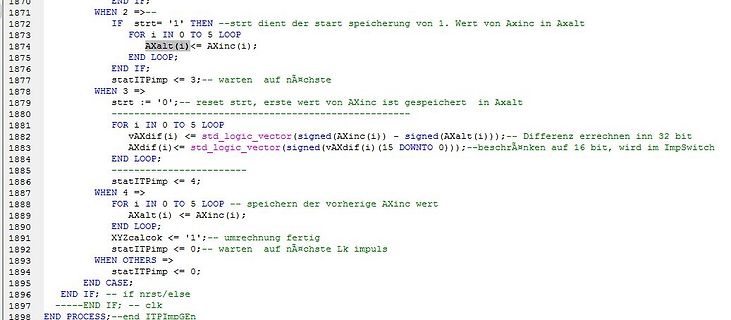
1870 END IF;
1871 WHEN 2 =>--
1872 IF strt='1' THEN --strt dient der start speicherung von 1. Wert von Axinc in Axalt
1873 FOR i IN 0 TO 5 LOOP
1874 Axalt(i)<= Axinc(i);
1875 END LOOP;
1876 END IF;
1877 statITPimp <= 3;--
to_integer(unsigned(A)); x<= to_integer(signed(B)); begin werk:process(A,B,clk,mode) begin case mode is when "00" => y<=t+x; when "01" => y<=t+2*x; when "10" => y<=2*t-x; when others => null; end case mode; if y>= 0 and y<=10 then gr<='1'; ge<='0'; rt<='0'; elsif y>=11 and y<=20 then gr<='0'; ge<='1'; rt<=
and regulations on the use of cellular devices in the area where you drive. Always obey them. Also, when using your modem while driving, please pay full attention to driving, pull off the road and park before making or answering a call if driving conditions so require. When applications are prepared for
where a battery disconnect switch or circuit breaker is needed. 5 V or Temp Temp To Non-Isolated others Amplifier / HallTo MCU Buck / LDO 5 V or Amplifier / Hall MCU DC/DC Sensor Sensor Sensor others Sensor Primary Secondary Secondary Primary Sensing Primary Current Temp Temp Current Sensing Secondary
data byte • After a STOP or REPEATED START has been received while still addressed as a Slave. • When a bus error has occurred due to an illegal START or STOP condition Bit Rate Generator The Bite Rate Generator unit controls the period of SCL when operating in a Master mode. The SCL period is controlled
", four when "100000", three when "100001", two when "100010", one when "100011", minus_one when "100101", minus_two when "100110", minus_three when "100111", three when "011000", two when "011001", one when "011010
", four when "100000", three when "100001", two when "100010", one when "100011", minus_one when "100101", minus_two when "100110", minus_three when "100111", three when "011000", two when "011001", one when "011010
", four when "100000", three when "100001", two when "100010", one when "100011", minus_one when "100101", minus_two when "100110", minus_three when "100111", three when "011000", two when "011001", one when "011010
end if; else AV := '0'; end if; if ENB = '1' then BV := B; else BV := '0'; end if; case F is -- AND when "00" => Y <= AV AND BV; -- OR when "01" => Y <= AV OR BV; -- NOT B when "10" => Y <= NOT BV; -- A + B when "11" => SUM := ("0"&AV) + ("0"&BV) +("0"&Cin); Y <= SUM(0); Cout <= SUM(1); when others =>
deviation of the actual ADC’s transfer function from the ideal straight line at zero input voltage. When the transition from output value 0 to 1 does not occur at an input value of ½ LSB, then we say that there is an offset error. With positive offset errors, the output value is larger than 0 when the
allow specifications (or models) from different providers (compa- nies) to be simulated together. When the language was first put to use, it was used for high-level behavioural simula- tion only. ’Synthesis’ into VLSI devices was made by manually converting the models into schematics using gates and
Network on 8300/8350/9300 Null command(note1) (note1) 7900/7950 Network off (note3) PWR ON(Note2) Others - EMP-61/81/830/835/740/745/821/828 returns “ERR” when it received commands other than PWR ON, PWR?, LAMP? and Null commands. (note2) EMP-7800/7850 returns “ERR” when it received commands other than
14 BRT i Brightness adjusting terminal 【Note5-10】 15 VR1 i Color video signal (Red)1 Positive (On when VSW=Hi.) 16 VG1 i Color video signal (Green)1 Ditto 17 VB1 i Color video signal (Blue)1 Ditto 18 GND1 i Ground 19 VR2 i Color video signal (Red)2 Positive (On when VSW=Lo.) 20 VG2 i Color video signal
out std_logic_vector (6 downto 0); -- parallel data output rdy : out std_logic; -- edge is issued when data word was updated reset : in std_logic); -- reset signal end entity ser2par; architecture ser2par_rtl of ser2par is signal sr0: std_logic_vector (3 downto 0); -- signal for uneven bits signal sr1
: PROCESS(CURRENT_STATE) --Vorgehen, beim Wechsel des Current-States. begin case CURRENT_STATE is when IDLE => RESULT_OUT <= "1111"; when STATE0 => NEXT_STATE <= STATE1; RESULT_OUT <= "0000"; when STATE1 => NEXT_STATE <= STATE2; RESULT_OUT <= "0001"; when STATE2 => NEXT_STATE <= STATE3; RESULT_OUT <= "0010"; when STATE3 => NEXT_STATE <= STATE0; RESULT_OUT <= "0011"; when others => NEXT_STATE <= STATE0; end case; end PROCESS STATE_DECODER; REG: PROCESS(CLK, RESET, START_STOP) begin if(RESET ='0') then -- Reset
Workaround Do not set FDIV = 1. 70 AT32UC3A 3. SPI Bad Serial Clock Generation on 2nd chip_select when SCBR = 1, CPOL=1 and NCPHA=0 When multiple CS are in use, if one of the baudrate equals to 1 and one of the others doesn't equal to 1, and CPOL=1 and CPHA=0, then an aditional pulse will be generated
>if DECODExC'event then v.dec_len := LENGTHxC; end if; -- Shift only when new data available if NEXTxC'event then v.dec_shift := v.dec_shift(31 downto 0) & DATAxC; v.dec_ptr := v.dec_ptr + 32; end if; Weiter oben hatte ich für den
F. D. schrieb im Beitrag #2572215: > -- Shift only when new data available > if NEXTxC'event then > v.dec_shift := v.dec_shift(31 downto 0) & DATAxC; > v.dec_ptr := v.dec_ptr + 32; > end if; Da liegt der Hund begraben
rising_edge(clk) then if ctr = 127 then ctr <= 0; else ctr <= ctr + 1; end if; case ctr mod 8 is when 4 => ram_addr <= std_logic_vector(to_unsigned(ctr / 8, 4)); when 5 => ram_en <= '1'; when 6 => ram_en <= '0'; when 7 => shiftreg <= ram_data; when others => null; end case; end if; end process; process
"010", d when "011", e when others; Seite 17 | Prof. Dr.-Ing. Ulrich Schmidt | 2011 Praktikum Rechnerarchitektur Versuch 2: hierarchisches Design a) Ansteuerung einer Siebensegmentanzeige Entwerfen Sie einen Decoder
, circuit described herein; neither does it convey any license under its patent nor the right of others. The datasheet is the official document of OmniVision. The applicaton notes are application guide lines for reference. If there are any difference between sensor datasheet and application notes, please
, circuit described herein; neither does it convey any license under its patent nor the right of others. The datasheet is the official document of OmniVision. The applicaton notes are application guide lines for reference. If there are any difference between sensor datasheet and application notes, please
bytes contained in the data packet. When the complete flag for the data packet is set, the master verifies that it has received the correct values. 5.3 Polled The polled code example uses the SPI driver to instantiate a master and slave. The
positions the source pointer back to the first ADC result register after the data transfer. Note that when using reload after a burst and the total byte count is not a multiple of the burst size, the last burst transfer will stop when the total byte count is reached, and the reload action occurs. For example
15 downto 0); Job: process begin wait until rising_edge(clk); Error <= '0'; case CommandAdress is when x"0001" => Value1 <= CommandValue; sMemAdress <= sMemAdress+1; when x"0002" => Value2 <= CommandValue; sMemAdress <= sMemAdress+1; when x"0003" => Value3 <= CommandValue; sMemAdress <= sMemAdress+1; when others => Error <= '1'; end case; end process Job; MemAdress <= std_logic_vector(to_unsigned(sMemAdress, MemAdress'length)); end Behavioral;
display data RAM is set in the display start line register and displayed at the top of the screen. When the display duty cycle is 1/64 or others(1/32 - 1/64), the data of total line number of LCD screen, from the line specified by display start line instruction, is displayed. blick da mit meinem
developers/tools/obsoletevids093009.pdf), wie z.B. MCS Electronics "That changed in June 2009 when USB-ORG wrote an email that it was not permitted to sell VID or PID. MCS pointed out that in The Netherlands you can not enforce or change rules AFTER a product/service is sold. So we continued as
noch sonst irgendwas ohne schriftliche Erlaubnis: > "They may not be sold, transferred, or used by others, directly or > indirectly, except in special circumstances and then only upon prior > writtenapproval by USB-IF. Unauthorized use ... are strictly > prohibited." Naja, außer man kann dem USB
pin for logic .(+5V) 4 V0 I Contrast control (VDD~VOUT) 5 /WR I Data write: Write data into T6963 when /WR is L. 6 /RD I Data Read: Read data from T6963 when /RD is L. 7 /CE I Chip enable for T6963: /CE must be L when CPU communicates with T6963 8 C/D I C/D /WR=L /RD =L L Data Write Data Read H Command
pin for logic .(+5V) 4 V0 I Contrast control (VDD~VOUT) 5 /WR I Data write: Write data into T6963 when /WR is L. 6 /RD I Data Read: Read data from T6963 when /RD is L. 7 /CE I Chip enable for T6963: /CE must be L when CPU communicates with T6963 8 C/D I C/D /WR=L /RD =L L Data Write Data Read H Command
This command clears the position and resets the software. While some user-set parameters are held, others return to the default values. See Table 2.2. This command may shorten the position fix time when long-distance travel occurs from the last fixed position. Note NMEA message continues outputting the
log : process (r, write_enable, read_enable) variable v : reg_type; begin v :=r; case r.state is when idle => if write_enable = '1' then v.state := write; elsif read_enable = '1' then v.state := read; else v.state := idle; end if; when write => v.buff(to_integer(unsigned(add_read))) := data_in; v.state := idle; when read => data_out <= std_logic_vector(r.buff(to_integer(unsigned(add_read)))); v.state := idle; when others => v.state := idle; end case; rin <= v; end process log; end Verhalten;
state_typ; begin if rising_edge(clk) and clk = '1' then next_state:= current_state; case current_state is when S0 => if zaehler1 >= 19 then rs <= '0'; rw <= '1'; NEXT_state:= S1; end if; when s1 => if zaehler2 >= 1 then rs <= '0'; rw <= '1'; csb <= '0'; Next_state:= s2; end if; when s2 => if zaehler3 >= 4 then
variable Next_state : state_typ; begin --if rising_edge(clk) and clk = '1' then case current_state is when S0 => if zaehler1 >= 19 then rs <= '0'; rw <= '1'; current_state<= S1; end if; when s1 => if zaehler2 >= 2 then rs <= '0'; rw <= '1'; csb <= '0'; current_state<= s2; end if; when s2 => if zaehler3 >
cs <='1'; o_cs <= '1'; FSM: process ( clk ) begin if rising_edge(clk) then case current_state is when S0 => if zaehler1 >= 19 then rs <= '0'; rw <= '1'; current_state<= S1; end if; when s1 => if zaehler2 >= 2 then rs <= '0'; rw <= '1'; csb <= '0'; current_state<= s2; end if; when s2 => if zaehler3 >
cs <='1'; o_cs <= '1'; FSM: process ( clk ) begin if rising_edge(clk) then case current_state is when S0 => if zaehler1 >= 19 then rs <= '1'; rw <= '0'; e <= '0'; current_state<= S1; end if; when s1 => if zaehler2 >= 2 then rs <= '0'; rw <= '1'; csb <= '0'; current_state<= s2; end if; when s2 => if
propagation delay (Vbridge = 0 V or 50 V) (Note 3) t − 100 170 ns OFF Shutdown propagation delay, when Shutdown is enabled t − 100 170 ns sd_en Shutdown propagation delay, when Shutdown is disabled t − 620 800 ns sd_dis Output voltage rise time (from 10% to 90CC@= 15 V) with 1 nF load r − 85 160 ns Output
spending your time on my problem. SPDA is a data pin of the Serial communication bus. it must be GND when not use
While it is not really obvious for me when I look at the picture, measuring height and width shows a clear deviation, yes. When you already use BT815 for extended font support, why not use pictures for the circles? After all, these have
disassembled and reassembled these scopes? Michael, what's the status of your scope? From the time when the scope worked I remember that it emitted quite a lot of heat, but I don't know from which of the chips it came. I only know that chips can degrade when they become too hot. Another personal experience
replacement makes my scope work again I will post the component I used for the repair - that should help others with the same problem. Michael
; Job: process(CommandAdress) begin DoneCommandIntern <= '0'; Error <= '0'; case CommandAdress is when x"0001" => Value1 <= CommandValue; DoneCommandIntern <= '1'; when x"0002" => Value2 <= CommandValue; DoneCommandIntern <= '1'; when x"0003" => Value3 <= CommandValue; DoneCommandIntern <= '1'; when others => Error <= '1'; end case; end process Job; MemAdressP: process(DoneCommandIntern) begin if (DoneCommandIntern = '1') then sMemAdress = MemAdress <= std_logic_vector(to_unsigned(sMemAdress+1, MemAdress'length
and Enable Receipt (CREN=1) BAUDCTL=0; } void putch(unsigned char data) { // Send Data when TXIF bit is ready while(!TXIF) continue; TXREG = data; } unsigned char getch(void) { // Get Data when RCIF bit is ready while(!RCIF) continue; return RCREG; } void main(void)
= 0x03; // Input for RA0 and RA1 TRISC = 0x07; // Set RC0,RC1 and RC2 as input others as Output ANSEL = 0x71; // Set PORT AN0, AN4, AN5 and AN6 as analog input ANSELH = 0x00; // Set PORT AN8 to AN11 as Digital I/O PORTC = 0x00; // Turn Off all PORTC /
treated as a Errata Sheet direct move to SCON such as MOV SCON,#IMM. These instructions may be used when it is not possible for the interrupt to occur at the same time as the instruction is being executed, which means in the following circumstances: A. The UART is not currently operating, or B. Within
dann so gemacht: [vhdl] oslv_byte <= std_logic_vector(u_tmp( (i_width-2) downto (i_width-9))) when u_tmp(i_width-1) = '0' else (others=>'1'); [/vhdl] Dadurch ist oben natürlich das ganze nichtlinear, was sich ja auch nicht vermeiden lässt es wird ja irgendwie auch der Wertebereich gestaucht.

 Bild