
-
Datei
atmega32u2.patch
21:47:45.259999715 +0100 @@ -4333,6 +4333,72 @@ }, { 0 }, // Xmega device descr. }, + // DEV_ATMEGA32U2 + // Get these data from the AVRStudio-Installation + // Atmel/AVR Tools/Partdescriptionfiles + { + "atmega32u2", + 0x958A, + 128, 256, // 32768 bytes flash + 4, 256, // 1024 bytes EEPROM + 29 * 4,
in „avarice und atmega32u2“ · Mikrocontroller und Digitale Elektronik ·
-
Datei
uart.c
UCSRA #define UART0_CONTROL UCSRB #define UART0_DATA UDR #define UART0_UDRIE UDRIE #elif defined(__AVR_ATmega8__) || defined(__AVR_ATmega16__) || defined(__AVR_ATmega32__) \ || defined(__AVR_ATmega8515__) || defined(__AVR_ATmega8535__) \ || defined(__AVR_ATmega323__) /* ATmega with one USART */ #define
in „SHT11 misst Mist“ · Mikrocontroller und Digitale Elektronik ·
-
Datei
OCR2.c
#include <avr/io.h> #include <inttypes.h> typedef uint8_t boolean; extern void OCR2_PWM(boolean B, boolean inverted, boolean fast, uint16_t prescaler, uint16_t value){ TCCR2A &= ~(0x03); TCCR2B &= ~(0x07); if(!B)
in „PWM funktion OCR1 atmega328p“ · Mikrocontroller und Digitale Elektronik ·
-
Datei
Dotmatrix.c
************************************************************************************* */ #include <avr/io.h> // µC Register einbinden #include <stdint.h> // Zahlenwerte (int) einbinden #define F_CPU 4000000 // Quarztakt bestimmen #include <util/delay.h> // Verzögerung einbinden #include "DotmatrixASCII.c
in „Von Arrays zu einem String“ · Mikrocontroller und Digitale Elektronik ·
-
Datei
ohne_kontrollausgabe.asm
c:\temp\arduino_build_705076/sketch_jul13a.ino.elf: file format elf32-avr Disassembly of section .text: 00000000 <__vectors>: 0: 0c 94 35 00 jmp 0x6a ; 0x6a <__ctors_end> 4: 0c 94 5d 00 jmp 0xba ; 0xba <__bad_interrupt> 8: 0c 94 5d 00 jmp 0xba ; 0xba <__bad_interrupt>
in „AVR Inline Optimierung kaputt?“ · Mikrocontroller und Digitale Elektronik ·
-
Datei
adc_display.c
#include <avr/io.h> #include <avr/interrupt.h> #include <avr/signal.h> #include <stdlib.h> #include <string.h> #include "../includes/display_lib.h" #define TIMER_16BIT 8000 #define TIMER_8BIT 200 #define ADC_REF_QUOT
in „AVR Timer + ADC“ · Mikrocontroller und Digitale Elektronik ·
-
Datei
SegDispPD.c
details */ #include <inttypes.h> #include <avr/io.h> #include <avr/pgmspace.h> #include "Config.h" #include "Base.h" #define SEGMENT(g, r, b) (g * 24 + r * 8 + b) // g is gndline 0 or 1 // r is number of shift register // b is bitvalue of segment
in „Bitte um Hilfe bei Code-Optimierung“ · Mikrocontroller und Digitale Elektronik ·
-
Datei
main.c
/* * ATmega32 - IBIS VDV300 Wandler ohne LCD (mit kontinuierlichem bidirektionalem UART-Transfer) * Funktionen: * - Hardware UART (PC <-> MCP2221A) * - Software UART (Wagenbus TX/RX) mit Timer-basiertem Bit-Banging
in „Codecontrolle und Fragen zu Microchip Studio“ · Mikrocontroller und Digitale Elektronik ·
-
Datei
deinterleave.h
#ifndef DEINTERLEAVE_H #define DEINTERLEAVE_H #include <inttypes.h> //#include <avr/pgmspace.h> const __flash uint8_t even_odd_bits[] = { 0, 1, 16, 17, 2, 3, 18, 19, 32, 33, 48, 49, 34, 35, 50, 51, 4, 5, 20, 21, 6, 7, 22, 23, 36, 37, 52, 53, 38, 39, 54, 55, 64, 65, 80, 81, 66, 67,
in „AVR/ATmega uint32_t Deinterleaving optimieren“ · Mikrocontroller und Digitale Elektronik ·
-
Datei
160102_ADC_Konfig.txt
Atmel Studio 7.0 ATTiny85 ________ #define F_CPU 1000000 // int.Takt auf 1MHz gestellt #include <avr/io.h> #include <util/delay.h> #define OBER_BEREICH (4*1023/5) #define MITTEL_BEREICH (OBER_BEREICH - UNTER_BEREICH) #define UNTER_BEREICH (3*1023/5) void ADC_Init(void) // ADC initialisieren { unsigned
in „ADC initialisieren, Grundlagen“ · Mikrocontroller und Digitale Elektronik ·
-
Datei
config.h
****************** */ /* MCU clock */ #define CPU_FREQ F_CPU /* * ATmega 328/328P */ #if defined(__AVR_ATmega328__) #include "config_328.h" /* * ATmega 324P/324PA/644/644P/644PA/1284/1284P */ #elif defined(__AVR_ATmega324P__) || defined(__AVR_ATmega644__) || defined(__AVR_ATmega1284__) #include "config
-
Datei
config.h
****************** */ /* MCU clock */ #define CPU_FREQ F_CPU /* * ATmega 328/328P */ #if defined(__AVR_ATmega328__) #include "config_328.h" /* * ATmega 324P/324PA/644/644P/644PA/1284/1284P */ #elif defined(__AVR_ATmega324P__) || defined(__AVR_ATmega644__) || defined(__AVR_ATmega1284__) #include "config
-
Datei
SPI.c
**************************************************************************************** #include <avr/io.h> #include <avr/interrupt.h> #include "SPI.h" //**************************************************************************************** //Variablen //*******************************************
in „Atmega88- Daten von Sensoren auf Flash abspeichern“ · Mikrocontroller und Digitale Elektronik ·
-
Datei
Lichtorgel.ino
zum abgleich des Eingangsspannungsteilers //Entwickelt 2015 von Christof Rieger //sollte auf allen AVR-8 Arduinos laufen mit 16MHz und mindestens mit ATmega168 //Ein Geschenk an die Arduinogemeinde. Die Vermarktung des Cods ist verboten !!! //#include <LiquidCrystal.h> //Der Wert der überschritten werden
in „5 Kanal Digital-Lichtorgel für Arduino“ · Projekte & Code ·
-
PDF
nRF24L01_.pdf
Schnittstelle im Arduinosystem verdoppelt werden. z.B. C:\Program Files (x86)\Arduino\hardware\arduino\avr\cores\arduino\HardwareSerial.h #define SERIAL_RX_BUFFER_SIZE 64 ändern in #define SERIAL_RX_BUFFER_SIZE 128 Arduino muss danach neu gestartet werden. Linuxsystem als Server Letztlich benötigt man einen
in „Repeating und Routing Netzwerk mit Arduino und nRF24L01+“ · Projekte & Code ·
-
Datei
ZndUhr01.asm
Hardwaredefinitionen einbinden .list ;Programm listen .listmac ;Makros listen .equ clock=3686400 ;Taktfrequenz des AVR .equ timer0ein=3 ;Bitmuster Timer0 mit Vorteiler 64 (LCD-Sync) .equ timer0swku=254-(clock/3200000) ;Startwert Timer0 für 20µs .equ timer0swla=254-(clock/42667) ;Startwert Timer0 für 1,5ms .equ tim1zu
in „Probleme mit USART (ATMEGA8535)“ · Mikrocontroller und Digitale Elektronik ·
-
Datei
ZndUhr01.asm
Hardwaredefinitionen einbinden .list ;Programm listen .listmac ;Makros listen .equ clock=3686400 ;Taktfrequenz des AVR .equ timer0ein=3 ;Bitmuster Timer0 mit Vorteiler 64 (LCD-Sync) .equ timer0swku=254-(clock/3200000) ;Startwert Timer0 für 20µs .equ timer0swla=254-(clock/42667) ;Startwert Timer0 für 1,5ms .equ tim1zu
in „Display Menü LCD 4x20“ · Mikrocontroller und Digitale Elektronik ·
-
Datei
1wire.c
THIS SOFTWARE, EVEN IF ADVISED OF THE POSSIBILITY OF * SUCH DAMAGE. */ #include <stdio.h> #include <avr/io.h> #include <avr/pgmspace.h> #include "1wire.h" #include "1wire-delay.h" #if OW_DEBUG void uart_putsP(const char *addr); void uart_puts(const char *addr); void uart_getc(); int uart_putc(char c);
in „DS18S20 Fehler ab ca. 40°C“ · Mikrocontroller und Digitale Elektronik ·
-
 Bild
Bild
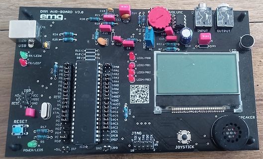
DMM AVR-BOARD V3.0 Leiterplatte mit LCD und Joystick
DMM AVR-BOARD V3.0 emg X1 USB LED6 RX/ LED7 TX R11 C19 R16 C12 C20 C15 R21 R18 C11 R25 R26 R12 R10 R9 R1 R2 R3 R24 R17 R5 R4 R13 R14 R15 R19 R20 R22 R23 R27 R28 R29 R30 R31 R32 R33 R34 R35 R36 R37 R38 R39 R40 R41 R42 R43 R44 R45 R46 R47 R48 R49 R50 R51 R52 R53 R54 R55 R56 R57 R58 R59 R60 R61 R62 R63 R64 R65 R66 R67 R68 R69 R70 R71 R72 R73 R74 R75 R76 R77 R78 R79 R80 R81 R82 R83 R84 R85 R86 R87 R88 R89 R90 R91 R92 R93 R94 R95 R96 R97 R98 R99 R100 R101 R102 R103 R104 R105 R106 R107 R108 R109 R110 R111
in „Suche Unterlagen zum DMM AVR-BOARD V3.0 der TU Braunschweig“ · Mikrocontroller und Digitale Elektronik · · Platinenfotos
-
Datei
SPI.c
#include <avr/io.h> #include "SPI.h" void SPI_init(uint8_t modus, uint8_t master,uint8_t interrupt,uint8_t takt_teiler, uint8_t LSB_first) { SPCR = 0; //Control Register komplett löschen if (master = 1) //Auswahl
in „AT90CAN128 und MCP2515-Controller“ · Mikrocontroller und Digitale Elektronik ·
-
PDF
ATmega16M1_ISP.pdf
commands. 6. Exit Programming mode by power the device down or by bringing RESET pin to 0V. ATmega16M1/32M1/64M1 [DATASHEET] 280 8209E–AVR–11/2012
in „ISP Pins am ATMega16M1“ · Mikrocontroller und Digitale Elektronik ·
-
Datei
Beispiel_Programm.txt
- void uartPutChar(char data) { //warte bis UDR leer ist UCSRA / USR bei z.B.: 2313 while (!(UCSRA&32)); //sende UDR=data; } void uartPutBin(char data) { //warte bis UDR leer ist UCSRA / USR bei z.B.: 2313 while (!(UCSRA&32)); //sende if (data&1) uartPutChar('1'); else uartPutChar('0'); if (data&2) uartPutChar
in „Programm läuft in schleife?“ · Mikrocontroller und Digitale Elektronik ·
-
Datei
display_test.c
#include <stdint.h> #include <avr/io.h> # define F_CPU 4000000UL #include <util/delay.h> #define LCD_SCL 1<<PB0 #define LCD_SDA 1<<PB1 #define LCD_DORC 1<<PB2 #define LCD_RESET 1<<PB4 #define LCD_SCE 1<<PB3 #define LCD_PORT PORTB void
in „Hilfe bei Nokia 3310 Display“ · Mikrocontroller und Digitale Elektronik ·
-
Datei
font_6x8.h
// 6 x 8 font // 1 pixel space at left and bottom // index = ASCII - 32 #include <avr/pgmspace.h> unsigned char font6_8[][6] PROGMEM = { { 0x00, 0x00, 0x00, 0x00, 0x00, 0x00 }, // sp { 0x00, 0x00, 0x00, 0x2f, 0x00, 0x00 }, // ! { 0x00, 0x00, 0x07, 0x00, 0x07, 0x00 }, //
in „Probleme mit dem LCD 4884 Shield“ · Mikrocontroller und Digitale Elektronik ·
-
Datei
tiny_oled_spi_3wire_b.ino
Direction Map oled_datamode(); for (y= 0; y< 8; y++) // ein Byte in Y-Achse = 8 Pixel... // 8*8Pixel = 64 Y-Reihen { oled_cmdmode(); spi_out(0xb0 | y); // Pageadresse schreiben spi_out(0x00); // MSB X-Adresse spi_out(0x00); // LSB X-Adresse (+Offset) oled_datamode(); for (x= 0; x< 128; x++) { if (bkcolor
in „ATtiny85 benötige Taster und kein freier Port“ · Mikrocontroller und Digitale Elektronik ·
-
Datei
kueche_2.lst
tatsächlich geht's nur mit 50Hz .equ T1Rate = 50 .equ T1Time = 1000 / 50 ;msec .equ T1Init = F_OSC / 64 / T1Rate - 1 ;T1 value .equ T1Prescale = 0<<CS12 | 1<<CS11 | 1<<CS10 ;/64 .if AVR==8515 .else .equ Watchdog = 1 .endif .equ DelayedKey = 5000 / T1Time ;5 seconds ; ; Buzzer ; .equ BZddr = ddrd .equ BZout
-
Datei
uart.c
UCSRA #define UART0_CONTROL UCSRB #define UART0_DATA UDR #define UART0_UDRIE UDRIE #elif defined(__AVR_ATmega8__) || defined(__AVR_ATmega16__) || defined(__AVR_ATmega32__) \ || defined(__AVR_ATmega323__) /* ATmega with one USART */ #define ATMEGA_USART #define UART0_RECEIVE_INTERRUPT USART_RXC_vect #
in „AVR Bootloader in C, geht mit mega8 nicht“ · Mikrocontroller und Digitale Elektronik ·
-
Datei
lcd_driver_st7565.c
Chip select: SPI_ENABLE_LCD) // we need to control line A0 (SPI_ADR0_LOW;SPI_ADR0_HIGH;) // #include <avr/io.h> #include <avr/interrupt.h> #include <avr/eeprom.h> #include <avr/pgmspace.h> // put var to program memory #include <util/delay.h> #include <stdio.h> #include "config.h" #include "cortos.h" #include
in „EA-DOGM128-6 mit ATMega88 und Assembler“ · Mikrocontroller und Digitale Elektronik ·
-
Datei
EKG.c
Einbinden von Bibliotheken + CPU-Takt Definition #define F_CPU 3686400 //µC-Takt definiern #include <avr\io.h> //Registernamen #include <avr/interrupt.h> //Interrupts #include <stdint.h> //Datentypen //Globale Vaiablen unsigned char UARTDatenEmpfangen = 1; //String wurde vom PC komplett empfangen bzw.
in „ATmega8 Timer0- / EEPROM-Fehler“ · Mikrocontroller und Digitale Elektronik ·
-
Datei
dac_adc.h
#include <avr/io.h> #define GAIN1 (0x03 | 0x80) #define GAIN2 (0x07 | 0x80) #define GAIN4 (0x0B | 0x80) #define GAIN8 (0x0F | 0x80) #define GAIN16 (0x13 | 0x80) #define GAIN32 (0x17 | 0x80) #define GAIN64 (0x1B |
in „atXmega 128 A3 - DAC“ · Mikrocontroller und Digitale Elektronik ·
-
Datei
Unterprogramme.h
UCSRA #define UART0_CONTROL UCSRB #define UART0_DATA UDR #define UART0_UDRIE UDRIE #elif defined(__AVR_ATmega8__) || defined(__AVR_ATmega16__) || defined(__AVR_ATmega32__) \ || defined(__AVR_ATmega8515__) || defined(__AVR_ATmega8535__) \ || defined(__AVR_ATmega323__) /* ATmega with one USART */ #define
in „Roboter-Linienverfolgung mit P-Regler und Ausweichmodus“ · Mikrocontroller und Digitale Elektronik ·
-
Datei
tn816def.inc
cycles (8ms) .equ FUSE_PERIOD_16CLK_gc = (0x02<<0) ; 16 cycles (16ms) .equ FUSE_PERIOD_32CLK_gc = (0x03<<0) ; 32 cycles (32ms) .equ FUSE_PERIOD_64CLK_gc = (0x04<<0) ; 64 cycles (64ms) .equ FUSE_PERIOD_128CLK_gc = (0x05<<0) ; 128 cycles (0.128s) .equ FUSE_PERIOD_256CLK_gc = (0x06<<0) ; 256
in „ATtiny816 wo finde ich def.inc“ · Mikrocontroller und Digitale Elektronik ·
-
Datei
app_bootloader.lst
home/tkl/workspace/hm-heat-control/release/execute/app_bootloader/app_bootloader.elf: file format elf32-avr Disassembly of section .text: 00003800 <__vectors>: 3800: 0c 94 2e 1c jmp 0x385c ; 0x385c <__ctors_end> 3804: 0c 94 56 1e jmp 0x3cac ; 0x3cac <__vector_1> 3808: 0c 94 4b 1c jmp 0x3896 ; 0x3896 <_
in „2 byte >> 1 word“ · Mikrocontroller und Digitale Elektronik ·
-
Datei
M8Timer1_geht_nicht.c
#include <avr/io.h> #include <stdio.h> #include <stdlib.h> #include <string.h> #include <avr/eeprom.h> #include <lcd-routines.h> #include <avr/interrupt.h> #define F_CPU 3686400 #include <util/delay.h> #include <
in „uC stürzt beu Zugriff auf MMC ab“ · Mikrocontroller und Digitale Elektronik ·
-
Datei
TMC222_AVR.c
************************************************* Example library for using a TMC222 together with AVR processors that have a hardware TWI interface (e.g. ATmega8, ATmega48, ATmega88, ATmega168, ATmega16, ATmega32, ATmega64, ATmega128, AT90CAN128 and many more). It implements and interrupt driven TWI
in „Ansteuerung TMC222“ · Mikrocontroller und Digitale Elektronik ·
-
Datei
Quelle.htm
Speicherkarte, MMC-Speicherkarte,Cluster,Formatieren ,Controller, Interface, pic, PIC, FAT32,16F877,16F876,16F84,pic16f84,PIC16F84,12F675,PIC12F675,cc5x.de.vu, C, source, compiler, cc5x, CC5X, Mplab, Microchip, programming, programm, RS232, Datenlogger, PIC16F871,16F871, Hobby
in „Dateizuordnungstabelle in FAT16“ · Mikrocontroller und Digitale Elektronik ·
-
Datei
usbcdc.c
// usbcdc.c // Source for USB CDC (Serial) Device // Muut '12 #include <avr/io.h> #include <avr/interrupt.h> #include <avr/pgmspace.h> #define EP0_FIFO_Size 8 const unsigned char des_endpoint0[] PROGMEM = { 7, // lenght 5, // endpoint descriptor 0, // endpoint 0 0, // control
in „AT90usb162 USB COM Interrupt wird nicht ausgelöst“ · Mikrocontroller und Digitale Elektronik ·
-
Datei
rgb.bas
'############################################################ ' Bascom AVR Test for the Powertip PH9867C CSTN Color Display ' This demo displays some colored diagonal stripes ' The Display uses the ST7626 Display Controler ' Tested on a ATMega8 set to 1Mhz internal osc '##
in „Mini-Farbdisplay (+mehr) für 1 Euro“ · Mikrocontroller und Digitale Elektronik ·
-
Datei
test.lst
test.out: file format elf32-avr Sections: Idx Name Size VMA LMA File off Algn 0 .text 00000076 00000000 00000000 00000054 2**1 CONTENTS, ALLOC, LOAD, READONLY, CODE 1 .debug_aranges 00000020 00000000 00000000 000000ca 2**0 CONTENTS
in „EEPROM Schreibfrequenz auf eine Adresse“ · Mikrocontroller und Digitale Elektronik ·
-
Datei
ADC_USART_Read_adc.h
represents GND and the maximum value represents the voltage on the AREF Author: Peniely Lydos AppNote: AVR500 - ADC implementation Datum: 26/05/2009 Version: 0.0 File Name: ADC_USART_Init_Read_adc.c ++++++++++++++++++++++++++++++++++++++++++++++++++++++++++++++++++++++++++++++++++++++++++++++++++++++++++
in „warnung:"[variable]may be used uninizialized"“ · Mikrocontroller und Digitale Elektronik ·
-
Datei
Bios_Analog.c
#include <avr/io.h> #include <stdint.h> #include <inttypes.h> #include <util/delay.h> void ADC_Init(void) { uint16_t result; // ADMUX = (0<<REFS1) | (1<<REFS0); // AVcc als Referenz benutzen ADMUX = (1<<REFS1) |
in „Atmega644 PWM Timer0 OCROB / A -Problem“ · Mikrocontroller und Digitale Elektronik ·
-
Datei
testrx.bas
############################################################# ' # RF01-Test Bascom ' # Pollin Funk-AVR Board - RFM01 ' ######################################################################## $regfile = "m8def.dat" $hwstack = 32 $swstack = 10 $framesize = 40 $crystal = 12000000 $baud = 38400 Baud = 38400
-
Datei
testrx.bas
############################################################# ' # RF01-Test Bascom ' # Pollin Funk-AVR Board - RFM01 ' ######################################################################## $regfile = "m8def.dat" $hwstack = 32 $swstack = 10 $framesize = 40 $crystal = 12000000 $baud = 38400 Baud = 38400
-
Datei
UART_receive.bas
############################################################# ' # RF01-Test Bascom ' # Pollin Funk-AVR Board - RFM01 ' ######################################################################## $regfile = "m8def.dat" $hwstack = 32 $swstack = 10 $framesize = 40 $crystal = 12000000 $baud = 38400 Baud = 38400
-
Datei
NRF24_SendRcvMIesp.ino
" #ifdef ESP8266 #define DISABLE_EINT noInterrupts() #define ENABLE_EINT interrupts() #else // für AVR z.B. ProMini oder Nano #define DISABLE_EINT EIMSK = 0x00 #define ENABLE_EINT EIMSK = 0x01 #endif #define RF_MAX_ADDR_WIDTH (5) #define MAX_RF_PAYLOAD_SIZE (32) #ifdef ESP8266 #define PACKET_BUFFER_SIZE
in „Wechselrichter Hoymiles HM-xxxx 2,4 GhZ Nordic Protokoll?“ · Mikrocontroller und Digitale Elektronik ·
-
Datei
NRF24_SendRcvMIesp.ino
" #ifdef ESP8266 #define DISABLE_EINT noInterrupts() #define ENABLE_EINT interrupts() #else // für AVR z.B. ProMini oder Nano #define DISABLE_EINT EIMSK = 0x00 #define ENABLE_EINT EIMSK = 0x01 #endif #define RF_MAX_ADDR_WIDTH (5) #define MAX_RF_PAYLOAD_SIZE (32) #ifdef ESP8266 #define PACKET_BUFFER_SIZE
in „Wechselrichter Hoymiles HM-xxxx 2,4 GhZ Nordic Protokoll?“ · Mikrocontroller und Digitale Elektronik ·
-
Datei
NRF24_SendRcvMIesp.ino
" #ifdef ESP8266 #define DISABLE_EINT noInterrupts() #define ENABLE_EINT interrupts() #else // für AVR z.B. ProMini oder Nano #define DISABLE_EINT EIMSK = 0x00 #define ENABLE_EINT EIMSK = 0x01 #endif #define RF_MAX_ADDR_WIDTH (5) #define MAX_RF_PAYLOAD_SIZE (32) #ifdef ESP8266 #define PACKET_BUFFER_SIZE
in „Wechselrichter Hoymiles HM-xxxx 2,4 GhZ Nordic Protokoll?“ · Mikrocontroller und Digitale Elektronik ·
-
PDF
DE200610__1_.pdf
I/O LPC 2103 FBD48 LQFP48 16k 4 4.10 · Watchdog-Timer ATMEGA 2560-16 AU TQFP-100 16 86 LPC 2119 FBD64 LQFP64 128k 16 10.00 · LxBxH:157 x ATMEGA 2560-8 AU TQFP-100 8 86 LPC 2129 FBD64 LQFP64 256k 16 10.95 102 x 40 mm 95 LPC 2131 FBD64 LQFP64 32k 8 5.85 ATMEGA 2561-16 AU TQFP-100 16 86 je13. LPC 2134 FBD64 LQFP64 128k 16 8.50 ATmega Flash-Memory: 64 kByte, LPC 2136 FBD64 LQFP64 256k 32 10.25 EEPROM: 512 Byte, RAM: 1 kByte LPC 2138 FBD64 LQFP64 512k 32 12.25 00 LPC 2194 JBD64 LQFP64 256k 16 12.90 ME LABJACK U12
in „ekg schaltung aus heft 10/2006“ · Analoge Elektronik und Schaltungstechnik ·
-
Datei
regler.c
AD-Wandlungen #define PWM_TOP 255 // PWM-Counter-TOP ( Achtung! hat Einfluss auf Timer ) #define KP 32 // P-Faktor der PI-Reglers = KP/16 #define KI 8 // I-Faktor der PI-Reglers = KI/16 #define TIMER_BIT 0 // definiert, welches Bit im Statusregister als Timer fungiert #define MODE_BIT 1 // Das Modebit
in „Code tut nicht was er soll Kanns der Compiler sein?“ · Mikrocontroller und Digitale Elektronik ·
-
Datei
RGB.c
/* Eine 8-kanalige PWM mit intelligentem Lösungsansatz ATmega32 @ 6 MHz */ // Defines an den Controller und die Anwendung anpassen #define F_CPU 6000000L // Systemtakt in Hz #define F_PWM 1000L // PWM-Frequenz in Hz #define PWM_PRESCALER 1 // Vorteiler für den Timer
in „Soft PWM noch zu schnell“ · Mikrocontroller und Digitale Elektronik ·
