conditions. - The LCD module is coated with a film to protect the display surface. Exercise care when peeling off this protective film since static electricity may be generated. u Storage Precautions When storing the LCD modules, avoid exposure to direct sunlight or to the light of fluorescent lamps
RAM to output register) Reset System reset can be initialized by setting RSTB terminal at low level when turning power on, receiving instruction from MPU. When RSTB becomes low, following procedure is occurred. - Display off - Display start line register becone set by 0.(Z-address 0) While RSTB is low
RAM to output register) Reset System reset can be initialized by setting RSTB terminal at low level when turning power on, receiving instruction from MPU. When RSTB becomes low, following procedure is occurred. - Display off - Display start line register becone set by 0.(Z-address 0) While RSTB is low
it really a problem? It seems to me that successful projects are often linked to one person, even when there are obviously a lot of others making significant contributions (like in the MyHDL project, thank you all!) Somehow it seems to give projects an identity.
continually have to clean up the mess behind them. http://stackoverflow.com/questions/6155675/when-should-i-use-std-logic-vector-and-when-should-i-use-other-data-types Jan
adc_key_in < 555) return btnLEFT; if (adc_key_in < 790) return btnSELECT; return btnNONE; // when all others fail, return this...[/avrasm] Es wäre nett wenn mir jemand von den AVR Spezis dabei helfen könnte ;-) Gruß
considerably reduce the design risks. If you do not agree with some rules, or want to suggest adding others, please fell free to contact me : Bert Cuzeau. Technical Manager ALSE - info@alse-fr.com. Conventions RTL : Register Transfer Level (almost equivalent to « synthesizable »). BEH : Behavioral code almost
dry conditions. -The LCD module is coated with a film to protect the display surface. Exercise care when peeling off this protective film since static electricity may be generated. Storage precautions When storing the LCD modules, avoid exposure to direct sunlight or to the light of fluorescent lamps.
than HB pencil lead. (2) Use fingerstalls of soft gloves in order to keep clean display quality, when persons handle the LCD module for incoming inspection or assembly. (3) When the surface is dusty, please wipe gently with absorbent cotton or other soft material. (4) Wipe off saliva or water drops
is the primary static parameter Those internal to the IGBT are dealt with by selecting an to use when calculating static variations as it directly relates appropriate device and those external to the IGBT are to the conduction loss of the transistor. The handled by good system design. This paper will
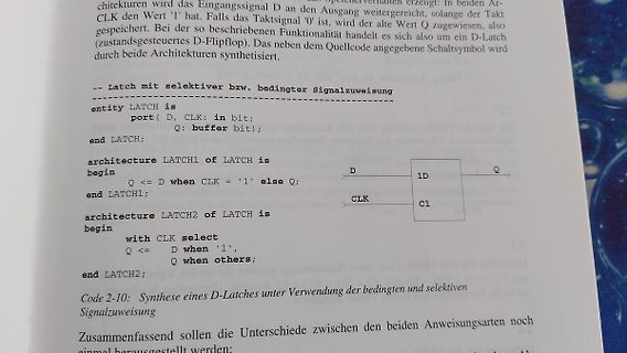
is
port( D, CLK: in bit;
Q: buffer bit);
end LATCH;
architecture LATCH1 of LATCH is
begin
Q <= D when CLK = '1' else Q;
end LATCH1;
architecture LATCH2 of LATCH is
begin
with CLK select
Q <= D when '1',
Q when others;
end LATCH2;
Code 2-10: Synthese eines D-Latches unter Verwendung der bedingten und
four LEDs are active low. LED0, LED2, and LED3 are shared with the three mechanical buttons (SW0:2). When turning an LED on, set the I/O pin to output low. When turning an LED off, set the I/O pin as input with pull-up. The protection circuitry added to the button will make the LED shine brighter when the
at the actual switching point. To get this noise as low as possible the ideal switching would be when the amplitude is 0 volt. The amplitude is crossing 0 volt at the sinus “zero crossing”. Switching mains in and out at the zero crossing requires a way of detecting when the next crossing will be and
at the actual switching point. To get this noise as low as possible the ideal switching would be when the amplitude is 0 volt. The amplitude is crossing 0 volt at the sinus “zero crossing”. Switching mains in and out at the zero crossing requires a way of detecting when the next crossing will be and
at the actual switching point. To get this noise as low as possible the ideal switching would be when the amplitude is 0 volt. The amplitude is crossing 0 volt at the sinus “zero crossing”. Switching mains in and out at the zero crossing requires a way of detecting when the next crossing will be and
4) for making and setting a cipher file. a. Erase This is a special command that is not verified. When it is executed, all data programmed to flash memory is erased. b. Full Operation This command is not verified. The old program is replaced by the new one even verification is unsuccessful. When the
"; Loadsignal <= '1'; NextSTATE <= NEWITERATION; when NEWITERATION=> AngleOutput<= "ZZZZZZZZZZZZZZZZ"; if Iteration = 11 then NextSTATE <= IDLE; else NextSTATE <= SUM; end if; when Sum=> AngleOutput<= "ZZZZZZZZZZZZZZZZ"; if AddCounter = 15 then NextSTATE
designed so as not to produce too much leakage current from high-voltage output of the inverter. When you design or order the inverter, please make sure that a poor lighting caused by the mismatch of the backlight and the inverter(miss lighting, flicker, etc.) never occur. When you confirm it, the module
Input 16 thData Byte 1 1 Scan on {D(7,y),D(5,y), S(1) ~S(96) D(3,y), D(1,y)} 0 0 Scan off Example: When y = 2, 1stScan Byte à Only S(2) is Scan on (11) while others are {S(96),S(95), S(94), S(93)} Scan off (00). The image represented by Data Bytes will be displayed on 2dhorizontal line Total displayed
Input 16 thData Byte 1 1 Scan on {D(7,y),D(5,y), S(1) ~S(96) D(3,y), D(1,y)} 0 0 Scan off Example: When y = 2, 1stScan Byte à Only S(2) is Scan on (11) while others are {S(96),S(95), S(94), S(93)} Scan off (00). The image represented by Data Bytes will be displayed on 2dhorizontal line Total displayed
Input 16 thData Byte 1 1 Scan on {D(7,y),D(5,y), S(1) ~S(96) D(3,y), D(1,y)} 0 0 Scan off Example: When y = 2, 1stScan Byte à Only S(2) is Scan on (11) while others are {S(96),S(95), S(94), S(93)} Scan off (00). The image represented by Data Bytes will be displayed on 2dhorizontal line Total displayed
Input 16 thData Byte 1 1 Scan on {D(7,y),D(5,y), S(1) ~S(96) D(3,y), D(1,y)} 0 0 Scan off Example: When y = 2, 1stScan Byte à Only S(2) is Scan on (11) while others are {S(96),S(95), S(94), S(93)} Scan off (00). The image represented by Data Bytes will be displayed on 2dhorizontal line Total displayed
; yout <= '0'; end if; when S1 => yout <= '0'; if ain = '1' then state <= S2; count_int <= count_int + 1; else state <= state; count_int <= count_int; end if; when S2 => yout <= '0'; if ain = '1' then state <= S0; count_int <= count_int + 1; else state <= state; count_int <= count_int; end if; when others => state <= S0; count_int <= "0000"; yout <= '0'; end case; end if; end if; end process; count <= std_logic_vector(count_int); end Behavioral;
downto 0)); end ALU; architecture Behavioral of ALU is begin Y <= signed(resize(A,8)) + resize(B,8) when op="00" else signed(resize(A,8)) + resize(B,8) + resize(B,8) when op="01" else signed(resize(A,8) + resize(A,8)) - resize(B,8) when op="10" else (others=>'0'); end Behavioral;
attribute KEEP of chain : signal is "true"; begin chain <= chain (14 downto 0) & not(input) when reset='0' else (others=>'0'); process ( chain) begin taps <= chain(15); [/vhdl]
set, be sure the module and your body have the same electric potential. Be sure to ground the body when handling the LCD modules. - Tools required for assembling, such as soldering irons, must be properly grounded. make certain the AC power source for the soldering iron does not leak. When using an electric
on send commands. Can you tell us, how you set up your terminal settings for the end of the line? When did you bought the module, what is its brand, what SW Version is displayed when you place the batteries and did you take a look to the board (does it look like this http://img407.imageshack.us/img407
versteht dann nicht was ihr hier schreibt. Please use english instead of german. I think it is good when jirji can read what you wrote. Artax
’, unlike others, works when an odd number of bytes are read—the last byte is simply copied (since there is nothing to swap it with). ‘sync’ Pad every input block to size of ‘ibs’ with trailing zero bytes. When used
ein State ging, den es garnicht gab und somit auch hingen blieb (hab auch sowas in meiner SM wie when others => State <= idel, dass hatte da aber keine Auswirkungen) Zu einen Punkt hätt ich gerne noch eine zweite Meinung. Der MPMC ändert laut Datenplatt seine Signale (auch Datenwort) mit der Steigenden
about all, then match those you find "by spec". Then try using the PC-interfaces, compare those when having found the matching "ultrazoom" types. Next option: compare the command list of those... Think it will take too much space here to list all numbers and ranges alltogether. Besides, not all
28 years now for say eight to ten scopes I handled and/or owned on a daily base). Besides, if and when necessary it's upto the distributor to handle repair, just as it is for "branded types", so I'm still not willing to pay more for internally identical products just because there's "some brand" on them
package duty ratio linearly from 0 to 100%. An over current protection function is built inside. When short protection function happens, the operation frequency will be reduced from Applications 180KHz to 48KHz. An internal compensation LCD Monitor and LCD TV block is built in to minimize external Portable
end nex_4_pwm; architecture Behavioral of nex_4_pwm is signal pwm_zaehler: unsigned(15 downto 0):=(others => '0'); begin led <= sw; RGB1_Red <= '1' when pwm_zaehler <= unsigned(sw); RGB1_Green <= '1' when pwm_zaehler <= unsigned(sw); RGB1_Blue <= '1' when pwm_zaehler <= unsigned(sw); process begin wait
resources, we obtain the following scheduling of the program Normal Operations This schedule is valid when the algorithm is running in standard operating condition, i.e. when the motor is operating (rotating) or is stopped. Indeed, position, speed and reference calcula- tions are refreshed when events occurs from the position sensors (hall effect sensors) or don't have to be done (when the motor is stopped in a stable and normal state). Figure 16. Task Scheduling When Normal Operation Computation of position, derivate speed, Edge on position sensor current reference PCINT9 interrupt
; end PWM; architecture rtl of PWM is -- Signale hierher signal count: unsigned (5 downto 0) := (others=>'0'); signal countout: integer range 0 to 31; signal PWM_out : std_logic :='0'; begin -- hier ungetaktete Kombinatorik count <= count+1 when rising_edge(clock) ; countout <= to_integer(count) when count(5)='0' else 31-to_integer(count(4 downto 0)); PWM_out <= '0' when count(5)= '0' else '1'; --process begin --wait until rising_edge(clock); -- getaktete Beschreibung hier --end process; -- ungetaktete Kombinatorik darf auch hier stehen end;
signals to form vector for case construct. rotary_in <= rotary_b_in & rotary_a_in; case rotary_in is when "00" => rotary_q1 <= '0'; rotary_q2 <= rotary_q2; when "01" => rotary_q1 <= rotary_q1; rotary_q2 <= '0'; when "10" => rotary_q1 <= rotary_q1; rotary_q2 <= '1'; when "11" => rotary_q1 <= '1'; rotary_q2 <= rotary_q2; when others => rotary_q1 <= rotary_q1; rotary_q2 <= rotary_q2; end case; end if; end process rotary_filter; -- -- The rising edges of 'rotary_q1' indicate that a rotation has occurred and the -- state of
signals to form vector for case construct. rotary_in <= rotary_b_in & rotary_a_in; case rotary_in is when "00" => rotary_q1 <= '0'; rotary_q2 <= rotary_q2; when "01" => rotary_q1 <= rotary_q1; rotary_q2 <= '0'; when "10" => rotary_q1 <= rotary_q1; rotary_q2 <= '1'; when "11" => rotary_q1 <= '1'; rotary_q2 <= rotary_q2; when others => rotary_q1 <= rotary_q1; rotary_q2 <= rotary_q2; end case; end if; end process rotary_filter; -- -- The rising edges of 'rotary_q1' indicate that a rotation has occurred and the -- state of
Design LCD Modules STN LCD Modules for Automobile STN LCD Modules for PDA Passive Matrix LCD Modules Others Graphic Type LCD Modules Stadard Design LCD Modules Character Type LCD Modules Introduction & Standard P-LCD Modules Modes Introduction • Hosiden offers from the panels only to module assemblies with
BREITE : unsigned(4 downto 0):="01000"; -- das ist der Wert 8. signal count : unsigned (5 downto 0):=(others=>'0'); signal countout : integer range 0 to 31; signal PWM_out : std_logic :='0'; begin -- hier ungetaktete Kombinatorik count <= count+1 when rising_edge(clock); countout <= to_integer(count) when count(5)='0' else 31-to_integer(count(4 downto 0)); PWM_0 <= '0' when count(5)= '0' else '1'; --process begin --wait until rising_edge(clock); -- getaktete Beschreibung hier --end process; -- ungetaktete Kombinatorik darf auch hier stehen end;
BREITE: unsigned(4 downto 0):="01000"; -- das ist der Wert 8. signal count: unsigned (5 downto 0) := (others=>'0'); signal countout: integer range 0 to 31; signal PWM_out : std_logic :='0'; begin -- hier ungetaktete Kombinatorik count <= count+1 when rising_edge(clock) ; countout <= to_integer(count) when count(5)='0' else 31-to_integer(count(4 downto 0)); PWM_out <= '1' when count >= BREITE else '0'; --process begin --wait until rising_edge(clock); -- getaktete Beschreibung hier --end process; -- ungetaktete Kombinatorik darf auch hier stehen end;
> SDRAM_State <= CMD_INHIBIT; > SDRAM_IState <= X"ff"; > SDRAM_Addr <= (others => '0'); > rdata <= (others => 'Z'); Dies funktioniert zwar in einer Simulation; die Synthese muss hier ein Register aus 8-Flipflops für "rdata" bauen, aber kein Flipflop kann ein
Pins treiben. Die Zuweisung muss in VHDL dann in etwa so aussehen: [vhdl] rdata <= "ZZZZZZZZ" when (tristate_ein = '1') ELSE datenausgabe; [/vhdl] Um nun dein Problem zu lösen: eventuell geht es wenn du diese Zuweisung ein eigenes verilog Modul (wrapper) schreibst, welches dann das Verilog
2.93 --- C V 3.43 --- SECTION X−X 1 N STYLES ON PAGE 2 Electronic versions are uncontrolled except when accessed directly from the Document Repository. DOCUMENT NUMBER: 98ASB42022B Printed versions are uncontrolled except when stamped “CONTROLLED COPY” in red. DESCRIPTION: TO−92 (TO−226) PAGE 1 OF 2 onsemi
Atmel AVR Smart Battery devices contain a very accurate low power bandgap voltage reference which when calibrated correctly has less than 90ppm/°C drift from –10°C to +70°C and absolute accuracy of typically +/-1mV. This is the reference used for the internal Voltage ADC and Coulomb Counting ADC. ATmega16HVA
in use. When using STK600 or a board making use of the AVR JTAG pinout, the standard JTAG connector can be used. When connecting to a board which makes use of the ARM JTAG pinout, the 10-pin "mini-squid" cable must
be held stable at SDA when SCL is high. Data can change value at SDA only when SCL is low. I2C PROTOCAL XGZP6857D_DataSheet_EN_V2.9 www.CFSensor.com 5 /6 Calibrated Pressure Sensor Series V2.9/20250812 GENERAL REGISTER DESC.
ausgelesen wird. Den Treiber der Schnittstelle habe ich wie folgt deklariert: [vhdl] PA <= PORTA when DIRA = '1' else (others => 'Z'); [/vhdl] Im Gesamtsystem soll dann dieser Port entweder nur als Eingang bzw. nur als Ausgang genutzt werden. Eine Umschaltung im laufenden System soll nicht erfolgen
operation ‘Tip Setup’. (See chapter 1.) 06. Temp Stepping - Temp: 1 – 50 (increment / decrement per click when changing tip temperature) 07. Password Set (used to lock the unit so others can not change settings) - Switch: On / Off (use the password, or not) - Lock: 1 – 60 minutes (password becomes active after

 Bild