-
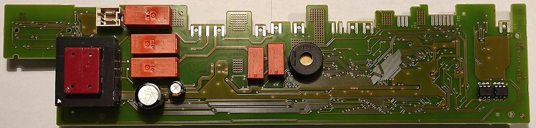
Bild
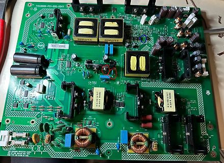
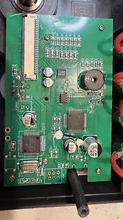
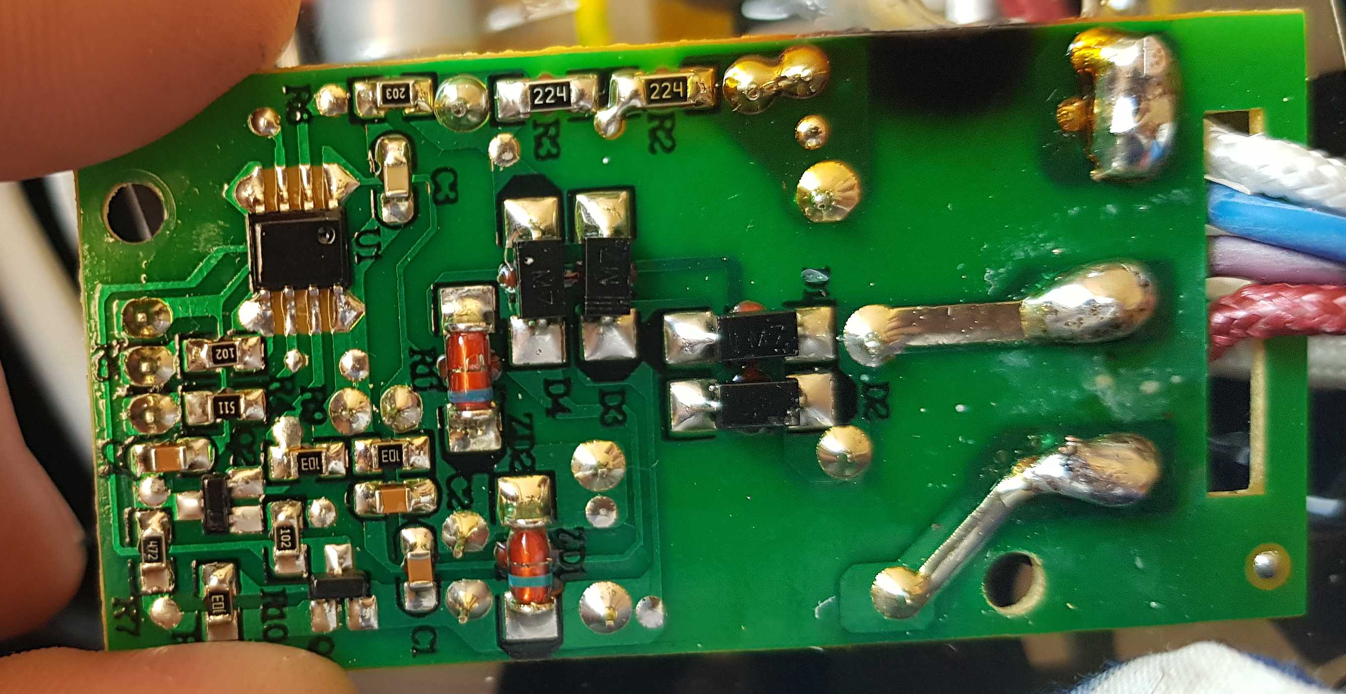
Leiterplatte eines Schaltnetzteils
L40, L41, L42, L43, L44, L45, L46, L47, L48, L49, L50, L51, L52, L53, L54, L55, L56, L57, L58, L59, L60, L61, L62, L63, L64, L65, L66, L67, L68, L69, L70, L71, L72, L73, L74, L75, L76, L77, L78, L79, L80, L81, L82, L83, L84, L85, L86, L87, L88, L89, L90, L91, L92, L93, L94, L95, L96, L97, L98, L99, L100
in „Suche nach Bauteil“ · Analoge Elektronik und Schaltungstechnik · · Platinenfotos
-
Bild
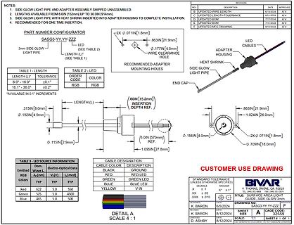
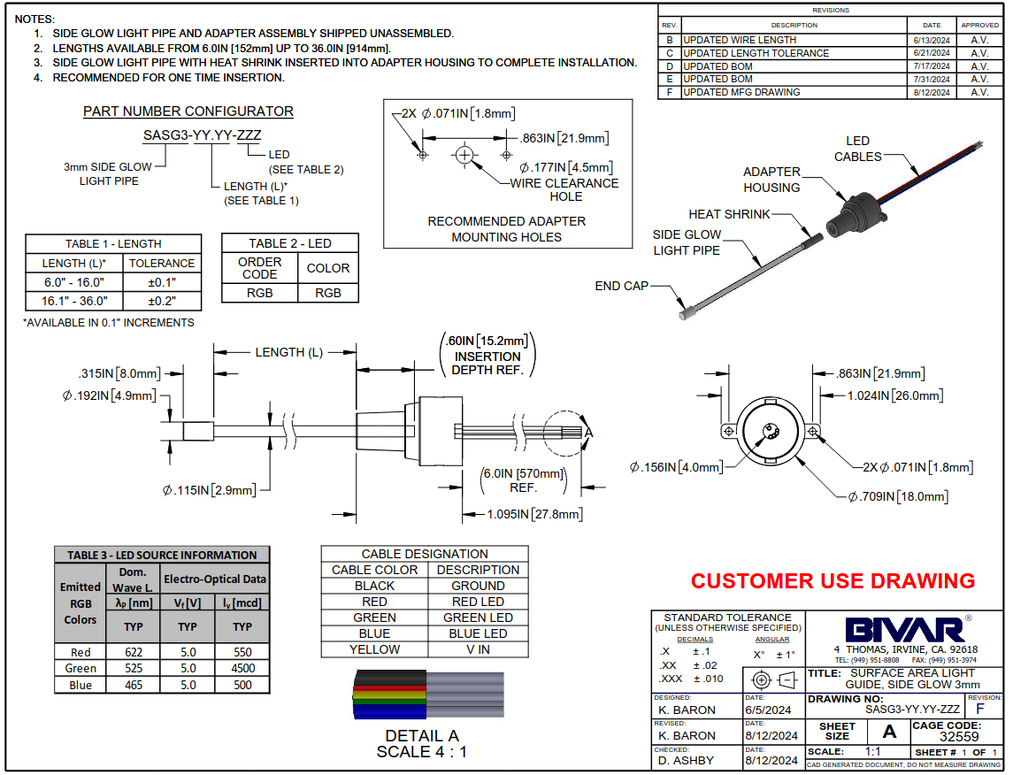
Technische Zeichnung einer LED-Leuchtleitung
16.1" - 36.0" ±0.2" *AVAILABLE IN 0.1" INCREMENTS TABLE 2 - LED ORDER CODE COLOR RGB RGB LENGTH (L) .60IN [15.2mm] INSERTION DEPTH REF. .315IN [8.0mm] .192IN [4.9mm] .115IN [2.9mm] .863IN [21.9mm] .177IN [4.5mm] .1024IN [26.0mm] .156IN [4.0mm] .709IN [18.0mm] END CAP SIDE GLOW LIGHT PIPE LED CABLES ADAPTER
in „Bauteil-Roundup: Drohnenkit bis Piezoputzanlage“ · Mikrocontroller und Digitale Elektronik · · Screenshots
-
Bild
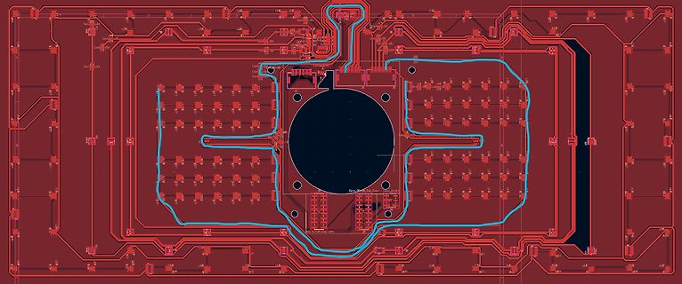
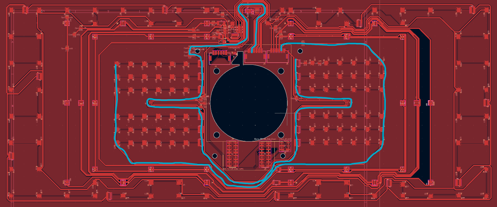
CAD-Ansicht eines Leiterplatten-Layouts
L40, L41, L42, L43, L44, L45, L46, L47, L48, L49, L50, L51, L52, L53, L54, L55, L56, L57, L58, L59, L60, L61, L62, L63, L64, L65, L66, L67, L68, L69, L70, L71, L72, L73, L74, L75, L76, L77, L78, L79, L80, L81, L82, L83, L84, L85, L86, L87, L88, L89, L90, L91, L92, L93, L94, L95, L96, L97, L98, L99, L100
in „LED-Platine summt“ · Analoge Elektronik und Schaltungstechnik · · Layouts
-
Bild
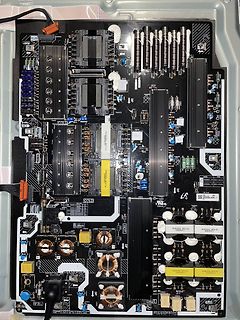
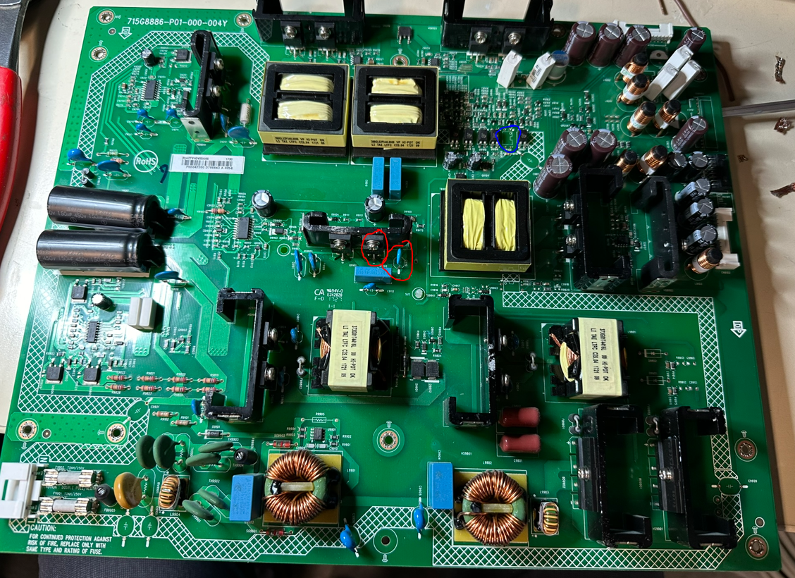
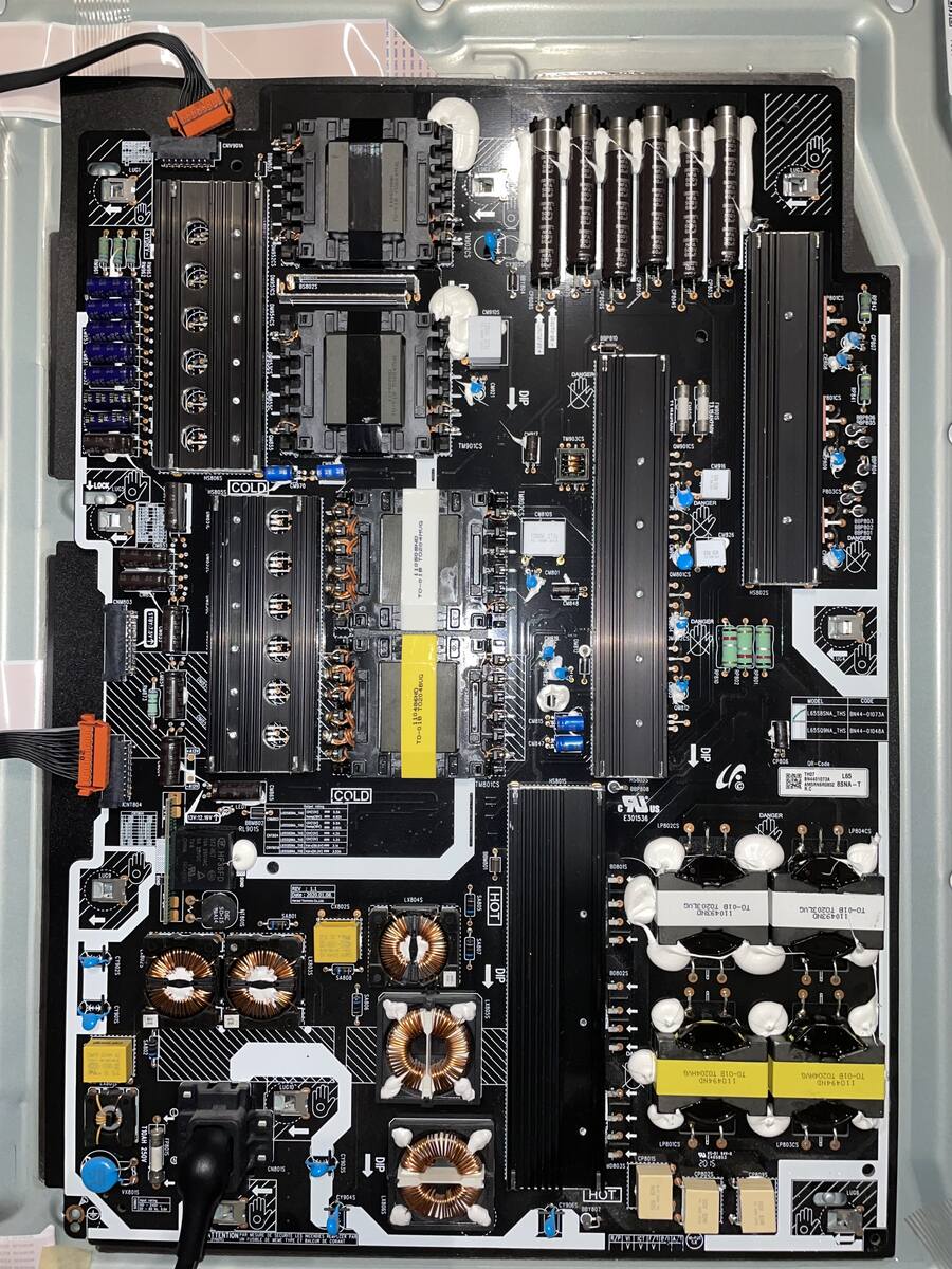
Leiterplatte eines Netzteils mit Kühlkörpern und Spulen
L40, L41, L42, L43, L44, L45, L46, L47, L48, L49, L50, L51, L52, L53, L54, L55, L56, L57, L58, L59, L60, L61, L62, L63, L64, L65, L66, L67, L68, L69, L70, L71, L72, L73, L74, L75, L76, L77, L78, L79, L80, L81, L82, L83, L84, L85, L86, L87, L88, L89, L90, L91, L92, L93, L94, L95, L96, L97, L98, L99, L100
in „Fernseher Defekt: Netzteil Schuld?“ · Analoge Elektronik und Schaltungstechnik · · Platinenfotos
-
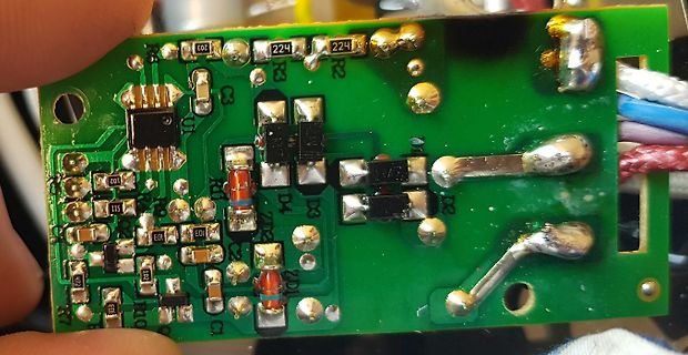
Bild
Foto einer bestückten Leiterplatte
L40, L41, L42, L43, L44, L45, L46, L47, L48, L49, L50, L51, L52, L53, L54, L55, L56, L57, L58, L59, L60, L61, L62, L63, L64, L65, L66, L67, L68, L69, L70, L71, L72, L73, L74, L75, L76, L77, L78, L79, L80, L81, L82, L83, L84, L85, L86, L87, L88, L89, L90, L91, L92, L93, L94, L95, L96, L97, L98, L99, L100
in „Bauteil gesucht - Transformator“ · Analoge Elektronik und Schaltungstechnik · · Platinenfotos
-
Bild
Foto einer bestückten Leiterplatte
L40, L41, L42, L43, L44, L45, L46, L47, L48, L49, L50, L51, L52, L53, L54, L55, L56, L57, L58, L59, L60, L61, L62, L63, L64, L65, L66, L67, L68, L69, L70, L71, L72, L73, L74, L75, L76, L77, L78, L79, L80, L81, L82, L83, L84, L85, L86, L87, L88, L89, L90, L91, L92, L93, L94, L95, L96, L97, L98, L99, L100
in „Wert des Widerstandes“ · Analoge Elektronik und Schaltungstechnik · · Platinenfotos
-
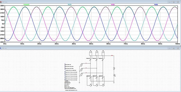
Bild
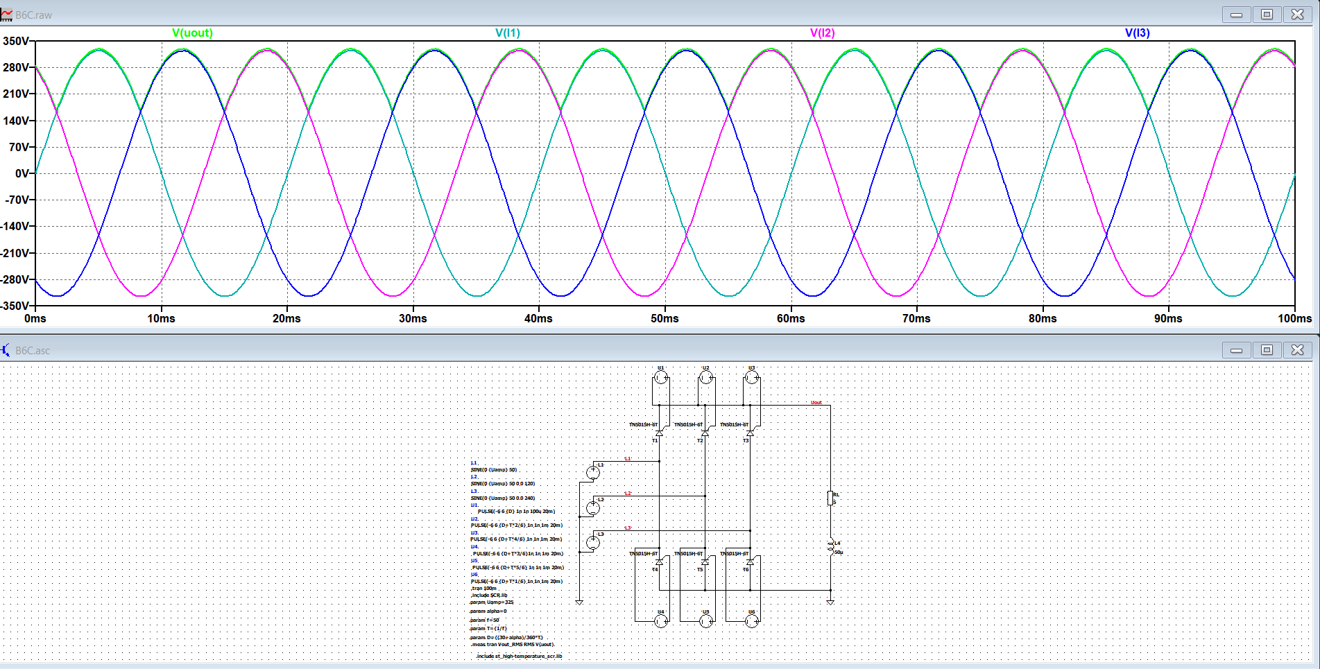
LTspice Simulation Schaltplan und Wellenformen
L35 L36 L37 L38 L39 L40 L41 L42 L43 L44 L45 L46 L47 L48 L49 L50 L51 L52 L53 L54 L55 L56 L57 L58 L59 L60 L61 L62 L63 L64 L65 L66 L67 L68 L69 L70 L71 L72 L73 L74 L75 L76 L77 L78 L79 L80 L81 L82 L83 L84 L85 L86 L87 L88 L89 L90 L91 L92 L93 L94 L95 L96 L97 L98 L99 L100 L101 L102 L103 L104 L105 L106 L107 L108
in „LTSpice Simulation B6C gesteuert“ · Analoge Elektronik und Schaltungstechnik · · Screenshots
-
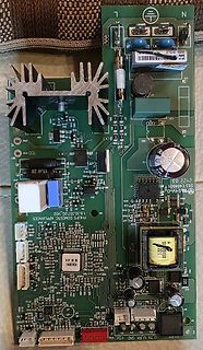
Bild
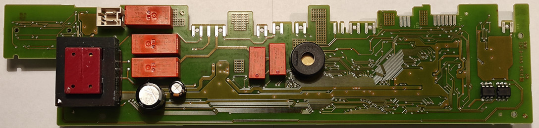
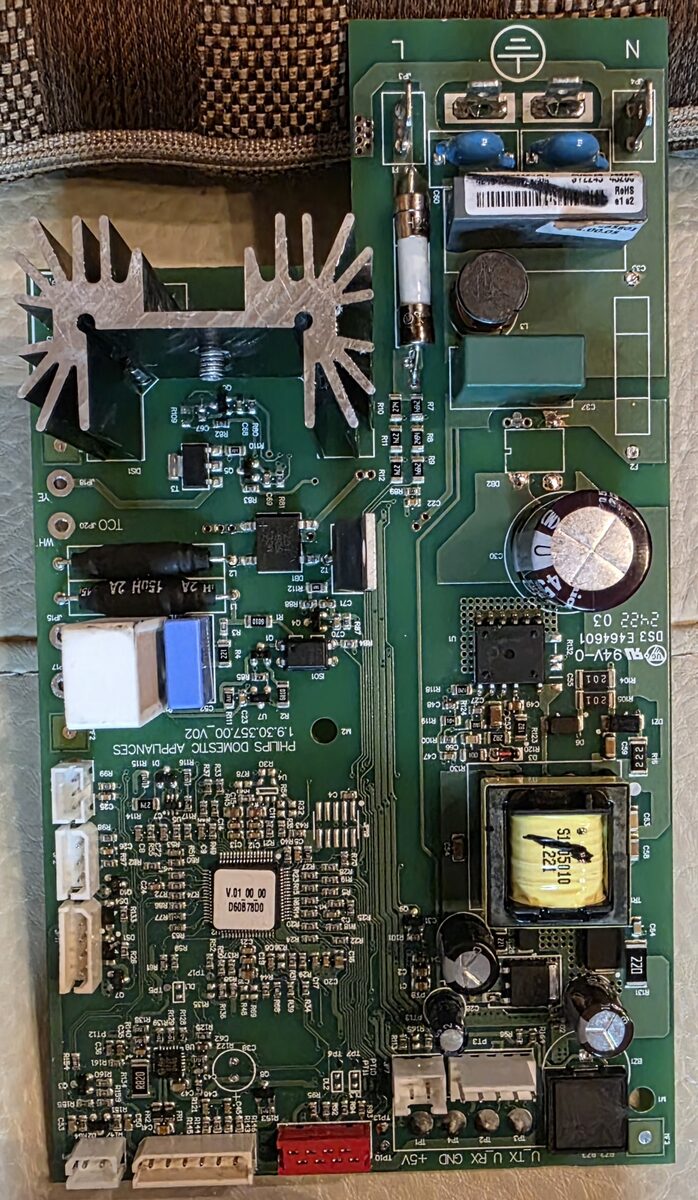
Bestückte Leiterplatte eines Philips Haushaltsgeräts
L35 L36 L37 L38 L39 L40 L41 L42 L43 L44 L45 L46 L47 L48 L49 L50 L51 L52 L53 L54 L55 L56 L57 L58 L59 L60 L61 L62 L63 L64 L65 L66 L67 L68 L69 L70 L71 L72 L73 L74 L75 L76 L77 L78 L79 L80 L81 L82 L83 L84 L85 L86 L87 L88 L89 L90 L91 L92 L93 L94 L95 L96 L97 L98 L99 L100 L101 L102 L103 L104 L105 L106 L107 L108
in „Steuerkarte Philips Kaffeautomat“ · Analoge Elektronik und Schaltungstechnik · · Platinenfotos
-
PDF
vestel_17ips71-r3_sch.pdf
R50 D7 D9 ST_BY R15 BC848B 1n Q3 V_3 1M 1M 1M V_4 4kV 2kV 10R BA159 1k BC848B 50V V_2 47p R49 SF10L60U R8 C55 C57 AUDIO_REG R7 1 C16 C2630V C38 10R D10 1k 1n R6 1n R52 50V 1k 4kV Q2 4n7 10R SF10L60U BC848B SMPS CONVERTER BLOCK R48 C C43 C41 100k 100k D17HER207 10R 129 C 56n 100n +400V R92 R97 C63 1k
in „TV PSU 17IPS71 Sekundärseitig Kurzschluss?“ · Analoge Elektronik und Schaltungstechnik ·
-
PDF
vestel_17ips71-r3_sch.pdf
R50 D7 D9 ST_BY R15 BC848B 1n Q3 V_3 1M 1M 1M V_4 4kV 2kV 10R BA159 1k BC848B 50V V_2 47p R49 SF10L60U R8 C55 C57 AUDIO_REG R7 1 C16 C2630V C38 10R D10 1k 1n R6 1n R52 50V 1k 4kV Q2 4n7 10R SF10L60U BC848B SMPS CONVERTER BLOCK R48 C C43 C41 100k 100k D17HER207 10R 129 C 56n 100n +400V R92 R97 C63 1k
in „L40f278x3cw-3DU Vestel 171ps71“ · Analoge Elektronik und Schaltungstechnik ·
-
Bild
Foto einer grünen Leiterplatte mit elektronischen Bauteilen
L85 L84 L83 L82 L81 L80 L79 L78 L77 L76 L75 L74 L73 L72 L71 L70 L69 L68 L67 L66 L65 L64 L63 L62 L61 L60 L59 L58 L57 L56 L55 L54 L53 L52 L51 L50 L49 L48 L47 L46 L45 L44 L43 L42 L41 L40 L39 L38 L37 L36 L35 L34 L33 L32 L3
in „FI-Tester für Arme aus Widerständen“ · Analoge Elektronik und Schaltungstechnik · · Platinenfotos
-
Bild
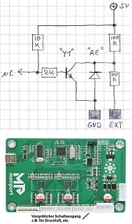
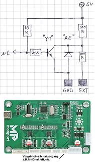
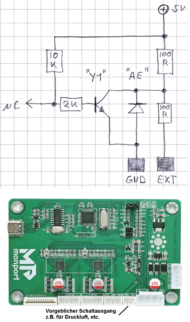
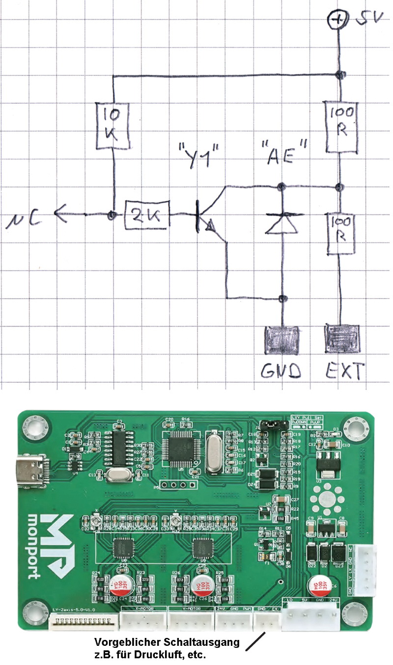
Handgezeichneter Schaltplan und Foto einer Leiterplatte
L35 L36 L37 L38 L39 L40 L41 L42 L43 L44 L45 L46 L47 L48 L49 L50 L51 L52 L53 L54 L55 L56 L57 L58 L59 L60 L61 L62 L63 L64 L65 L66 L67 L68 L69 L70 L71 L72 L73 L74 L75 L76 L77 L78 L79 L80 L81 L82 L83 L84 L85 L86 L87 L88 L89 L90 L91 L92 L93 L94 L95 L96 L97 L98 L99 L100 L101 L102 L103 L104 L105 L106 L107 L108
in „Enträtselung einer Schaltung (Laser)“ · Analoge Elektronik und Schaltungstechnik · · Fotos
-
PDF
dcf77-em2sn-dd.pdf
Empfängerempfindlichkeit a) bei Generatorspeisung typ 0,7 µV b) mit Antenne bei ungestörtem Empfang < 25 µV/m Antenne: l=60mm, d=10mm, C=2,2nF Ausgangsstrom open collector npn < 2 mA max. Ausgangsspannung 30 V Ausgangspegel bei 100% 77,5kHz-Träger < 0,4 V Ausgangspegel bei 25% 77,5kHz-Träger Ausgangsspannung U B Ausgangsimpulsbreite
in „Um welches Bauteil handelt es sich bei U1?“ · Mikrocontroller und Digitale Elektronik ·
-
PDF
Littelfuse_Thyristor_Kxxxzy.pdf
RATING o i m a p T r l t 100 B u i a M b C e )B m ° P I( A ) 80 Kxxx0G i n l T i e a ( e u w e C l 60 Kxxx0S R A Kxxx0E m u i 40 Kxxx2G a M 25 20 0.0 0.2 0.4 0.6 0.8 1.0 1 20 30 40 50 60 70 80 90 100 110 120 130 RMS On-State Current [I T(RMS)-Amps JunctionTemperature (T ) -J °C Figure 11: Dynamic Holding
in „OLYMP Gastherme GasStar Compact 8-27kW Zündgerät defekt.“ · Haus & Smart Home ·
-
Datei
drehzahlmesser.c
Akkumulatormethode Drehzahl_akku -= Drehzahl_buffer[Drehzahlzuweisung] Drehzahl_buffer[Drehzahlzuweisung] = 125000L*60 / Periode; Drehzahl_akku += Drehzahl_buffer[Drehzahlzuweisung] Drehzahl = Drehzahl_akku / 16; UpdateDisplay = 0; } if (overflow >= 2) { Drehzahl = 0; Drehzahl_akku =0; for (i=0; i<16; i++) { Drehzahl_buffer
in „Buchstaben Variablen auf LCD ausgeben AVR-GCC“ · Mikrocontroller und Digitale Elektronik ·
-
PDF
MR750_60.pdf
Reverse Voltage VR(RMS) 35 70 140 280 420 560 700 V Maximum Average Rectified Forward Current 22 (L= 60 °C , 1/8" Lead Lengths) IF(AV) A (Halfwave, single phase , 60Hz peak) 6 (Ta = 60 °C , P.C. Board mounting) Maximum Non-Repetitive Peak Forward Surge Current IFSM 400 (for 1 cycle) A (surge applied
in „MR760 Diode Ersatz für PFC Kreis“ · Analoge Elektronik und Schaltungstechnik ·
-
PDF
LT1498.pdf
ISINK= 2.5mA l 110 220 mV VOH Output Voltage Swing (High) (Note 6) No Load l 3.5 20 mV I = 0.5mA l 60 120 mV SOURCE ISOURCE= 2.5mA l 170 350 mV ISC Short-Circuit Current V S 5V l ±5 ±15 mA V = 3V l ±5 ±15 mA S IS Supply Current per Amplifier l 2.4 3.0 mA GBW Gain-Bandwidth Product (Note 7) l 5.8 8.5
in „KSQ für LED mit OPV“ · Analoge Elektronik und Schaltungstechnik ·
-
Datei
INT0_Test_x2.bas
lds r24,sreg 'Statusregister einlesen und push r24 'auf den Stack schieben push r25 lds R24,Count0_l '$60 = Low byte erhöhen lds R25,Count0_h adiw R24:R25,1 'Addition Word+1 brne C0 sbiw R24:R25,1 'wieder auf $FFFF=Maximum setzen C0: sts Count0_l,R24 'zurück schreiben Sts Count0_h,R25 lds R24,Count1_l
in „Code optimieren“ · Mikrocontroller und Digitale Elektronik ·
-
PDF
ecliptek13.575MHz.pdf
Ramp-up Rate (TLto TP) 3°C/second Maximum Time Maintained Above: - Temperature (TL) 217°C - Time (tL) 60 - 150 Seconds Peak Temperature (TP) 260°C Maximum for 10 Seconds Maximum Target Peak Temperature (TPTarget) 250°C +0/-5°C Time within 5°C of actual peak (tp) 20 - 40 seconds Ramp-down Rate 6°C/second
in „13,575Mhz Quarz für Fernbedienung - wo gibts den?“ · Mikrocontroller und Digitale Elektronik ·
-
PDF
DatenblattOriginalLEDAiptekt20.pdf
Current (mA) RELATIVE FLUX VS. CURRENT (T = 25°C) J 160 ) % 140 ( x 120 l F 100 u o 80 Amber i m L 60 e i 40 a e 20 R 0 0 100 200 300 400 500 Forward Current (mA) TYPICAL SPATIAL DISTRIBUTION 120 ) % ( 100 y i s n 80 t n White I s 60 Blue, Royal Blue o n Red, Red-Orange, Amber i Green m 40 u L e i 20
in „Abstrhlfläche LED“ · Mikrocontroller und Digitale Elektronik ·
-
PDF
EC20-9822_SK9822-2020__LED_Datasheet.pdf
Performance Graph: Thermal PadTemperaturevs.RelativeLightOutput 120% x BLUE/GREEN l s100% o i80% u L60% RED e l a40% o N20% 0.00 0 20 40 60 80 100 120 Thermal PadTemperature(T=25°C) WavelengthCharacteristics n100% GREEN t BLUE i80% RED t D n60% s i m40% e t l20% R 0.00 400 450 500 550 600 650 700 750
-
PDF
LED-RGB-SK6812RGBP8.pdf
Performance Graph: Thermal PadTemperaturevs.RelativeLightOutput 120% x BLUE/GREEN F100% s o i80% u L60% RED e l m40% o N20% 0.00 20 40 60 80 100 120 0 ThermalPadTemperature(T=25°C) WavelengthCharacteristics 100% n GREEN t BLUE i 80% RED t D n 60% s i m 40% e t l20% R 0.00 400 450 500 550 600 650 700
in „RGBW Led Stripe 12V LED Typ unbekannt“ · Mikrocontroller und Digitale Elektronik ·
-
PDF
DAtenblatt.pdf
O.V.P. Derating Curve Static Characteristics (24V) 32 350 100 ) 28 300 - V p 80 ( 24 250 m G ( A L 60 L 20 200 P ) V R ( T 16 150 T D 40 U U A T 12 100 T L U U 20 O 8 50 O -10 0 10 20 30 40 50 60 (VERTICAL) -10 0 45 55 (HORIZONTAL) 60 80 100 120 140 160 180 200 220 240 264 AMBIENT TEMPERATURE ( ) INPUT
in „Leerlaufverbrauch von Netzteilen“ · Mikrocontroller und Digitale Elektronik ·
-
PDF
S-350-27_datasheet.pdf
Curve Static Characteristics (24V) Ta=25 32 300 100 S-350-24~48V 28 250 p ) p 80 ( V E 24 200 ( A L 60 L 20 150 P ) S-350-5~15V O I % V 16 100 R D 40 U U A T 12 50 T O U U L 20 O 8 25 O -10 0 10 20 30 40 50 60 (HORIZONTAL) 160 170 180 190 200 210 220 230 240 250 260 AMBIENT TEMPERATURE ( ) INPUT VOLTAGE
in „[V] 14 Netzteile 27V 13A“ · Markt ·
-
PDF
DARC-Radio_BX-071.pdf
Kabelbinder diert, um ihn eventuell später ohne Lötar- ist die Polarität zu beachten. Die beiden 0,3 mm CuL, 60 cm beiten wieder von der Platine entfernen parallelen Bohrungen können als Zugent- IC-Sockel, 16-polig Platine und in einem anderen Projekt einsetzen zu lastung genutzt werden. können. Zum Schluss
in „Radiobasteln - Was hat 2018 noch Aussicht auf Erfolg- eine Anregung“ · HF, Funk und Felder ·
-
PDF
DARC-Radio_BX-071.pdf
Kabelbinder diert, um ihn eventuell später ohne Lötar- ist die Polarität zu beachten. Die beiden 0,3 mm CuL, 60 cm beiten wieder von der Platine entfernen parallelen Bohrungen können als Zugent- IC-Sockel, 16-polig Platine und in einem anderen Projekt einsetzen zu lastung genutzt werden. können. Zum Schluss
in „Versuch eines Audioverstärkers.“ · Analoge Elektronik und Schaltungstechnik ·
-
PDF
Teileliste.pdf
07220RL 106 RC0603FR-0722KL 11 RC0603FR-072R4L 59 RC0603FR-07240RL 107 RC0603FR-0724KL 12 RC0603FR-072R7L 60 RC0603FR-07270RL 108 RC0603FR-0727KL 13 RC0603FR-073RL 61 RC0603FR-07300RL 109 RC0603FR-0730KL 14 RC0603FR-073R3L 62 RC0603FR-07330RL 110 RC0603FR-0733KL 15 RC0603FR-073R6L 63 RC0603FR-07360RL 111 RC0603FR
in „[V] SMD-Widerstandssortimente 0603 YAGEO E12/E24“ · Markt ·
-
PDF
SPV-300-spec.pdf
Manual 1.External Voltage Control Vout 120 +V 100 100 +V -V LOAD % 80 Non-Linear % 80 -V E T G E L 60 R 60 O U PV T 40 T 40 P P 1~5.5V U U -V O 20 O 20 V V 1 2 3 4 5 5.5 6 20 40 60 80 100 110 120 EXTERNAL VOLTAGE (DC) OUTPUT VOLTAGE (%) File Name:SPV-300-SPEC 2011-08-23
in „Mean Well Spannungsmanipulation“ · Analoge Elektronik und Schaltungstechnik ·
-
PDF
AQV234.pdf
Continuous load current: 120 mA (DC) 120 50 2.5 A Ω s m100 e , n n40 m2.0 r 80 i t c e30 o1.5 a n r L 60 O T 20 1.0 40 10 0.5 20 0 0 0 –40 –20 0 20 40 60 8085 –40 –20 0 20 40 60 8085 –40 –20 0 20 40 60 8085 Ambient temperature, °C Ambient temperature, °C Ambient temperature °C All Rights Reserved © COPYRIGHT
in „Verk. Verschiedenes“ · Markt ·
-
PDF
WT_SKM.pdf
3) g bis 2 Watt 1 Entfällt 1 Entfällt u 2 bis 60 Watt 1 1 1 1 Leistung i Je mehr Leistung, desto L 60 bis 1000 Watt 1 2 2 1 kräftiger pustet der Fön oder über 1000 Watt 1 2 2 2 erwärmt die Mikrowelle das Spannung 1 Entfällt 1 1 Essen. Nicht alle Testkandidaten Handhabung 35% befried. (2,8) gut (2,0)
in „Wie funktioniert ein Leistungsmessgerät?“ · Mikrocontroller und Digitale Elektronik ·
-
PDF
Rail.pdf
20 2 PID120 PID1201 5K1 10K P I P 4 0 1G4x P IP 1 20 14x ROR6 COL6 R2R 1 1 1 X11 PIR601 PIR602 P I L 60 1 P I L 6 0 2 G3x G3x PIR210 PIR102 X11 F2MF F2MF AST0250204 AST0250204 5K1 R1R 4 10K R3R 0 X12 PIR1401 PIR402 P IL 14 01 PI L1L4L024 G4x G4x PIR001 PIR002 X12 P5P CP1P 3 CDD5 D1D 3 5K1 10K 2 P I P
in „Verständnis Frage, 1 Ausgang steuert 4?“ · Mikrocontroller und Digitale Elektronik ·
-
PDF
ATXK_H11_32768.pdf
smaxto TP) 3°C/sec. max 3°C/sec. max Liquidous temperature (T ) L 183°C 217°C Time at liquidous (tL) 60 - 150 sec. 60 - 150 sec. Peak package body temperature (T )* P see Table 1 see Table 2 Time (tp)** within 5°C of the specified classification temperature (T )C 20 sec. 30 sec. Ramp-down rate (T topT
in „Anschluss TCXO“ · Analoge Elektronik und Schaltungstechnik ·
-
PDF
AK-450_Series_Datasheet.pdf
De-rating Curve: Load V.S Temp. Load V.S I/P Voltage Ta=25°C 100 100 90 80 ) )80 ( ( d60 d70 o L L 60 40 50 20 40 -20 0 10 20 30 40 50 60 70 90 100 110 120 264 Ambient Temperature (°C) Input Voltage (Vac) Peak Load: I T-peak T-PEAKrepresents the period during which the output current is at 110% to 150%
in „[V] 30V/15A + 5V/0,3A Schaltnetzteil Cotek AK-450-30“ · Markt ·
-
PDF
CS4272_F1.pdf
detail) Figure 24. DAC Single Speed (fast) Passband Ripple 0 0 20 20 ) 40 40 B B ( ( d e i u p 60 l 60 m m A A 80 80 100 100 120 0.4 0.5 0.6 0.7 0.8 0.9 1 120 Frequency(normalized to Fs) 0.4 0.42 0.44 0.46 0.48 0.5 0.52 0.54 0.56 0.58 0.6 Frequency(normalized to Fs) Figure 25. DAC Single Speed (slow)
in „darf der Chip so warm werden?“ · Mikrocontroller und Digitale Elektronik ·
-
PDF
CS4272.pdf
detail) Figure 24. DAC Single Speed (fast) Passband Ripple 0 0 20 20 ) 40 40 B B ( ( d e i u p 60 l 60 m m A A 80 80 100 100 120 0.4 0.5 0.6 0.7 0.8 0.9 1 120 Frequency(normalized to Fs) 0.4 0.42 0.44 0.46 0.48 0.5 0.52 0.54 0.56 0.58 0.6 Frequency(normalized to Fs) Figure 25. DAC Single Speed (slow)
in „was ist "ATAPI channel mixing" Warum kein Ausgangssignal?“ · Mikrocontroller und Digitale Elektronik ·
-
PDF
PT4115E.pdf
Current vs Supply Voltage Supply Current vs Supply Voltage 120 250 110 V n 100 200 V 90 e 80 g 70 A150 l 60 ( o i V 50 I100 p 40 p 30 S 20 50 10 0 0 0 5 10 15 20 25 30 0 5 10 15 20 25 30 Iin(uA) Supply Voltage Vin(V) LED Current vs Vdim 600 Output Current vs Dim Duty Cycle 800 20KHz 700 R=0.13ohm A500 100Hz
in „PT4115 KSQ raucht ab. Gleichrichter nötig?“ · Analoge Elektronik und Schaltungstechnik ·
-
PDF
PT4115E_Copy.pdf
Current vs Supply Voltage Supply Current vs Supply Voltage 120 250 110 V n 100 200 V 90 e 80 g 70 A150 l 60 ( o i V 50 I100 p 40 p 30 S 20 50 10 0 0 0 5 10 15 20 25 30 0 5 10 15 20 25 30 Iin(uA) Supply Voltage Vin(V) LED Current vs Vdim 600 Output Current vs Dim Duty Cycle 800 20KHz 700 R=0.13ohm A500 100Hz
in „Driver IC für High Power LED bis max 3Euro“ · Mikrocontroller und Digitale Elektronik ·
-
PDF
Littelfuse_PulseGuard-ESD_PGB1.pdf
(max)oTL- Ramp-up Rate ▯¡$▯TFDPOE▯NBY -Temperature (T ) (Liquidus) ▯▯▯¡$▯ Reflow L -Temperature (t L 60 – 150 seconds PeakTemperature (T )P 260°C #BTFE▯PO▯*1$▯+&%&$▯+▯45%▯▯▯▯ Time within 5°C of actual peak Temperature (t p 10 – 30 seconds Ramp-down Rate ▯¡$▯TFDPOE▯NBY Time 25°C to peakTemperature (T P
in „Überspannungsschutz ?“ · Mikrocontroller und Digitale Elektronik ·
-
Datei
ATB_Grapik_Bus_Prg_1.c
Graphik_Rechteck(10,10,37,25); Graphik_Rechteck(20,15,47,30); Graphik_Auswahl_Font(4); Graphik_Text_ausgabe_L(60,25,"(Bild 4)"); Graphik_Gerade(5,5,85,5); // Gerade von x1,y1 zu x2,y2 Graphik_Gerade_weiter(70,15); // Gerade weiter zu x,y Graphik_Gerade_weiter(90,8); Graphik_Gerade_weiter(110,25); Graphik_Bereich_Muster
in „I2C Bus und eDIP128 (Graphik Display)“ · Mikrocontroller und Digitale Elektronik ·
-
PDF
STP16NF_--_156110-da-01-en-PWRMOS_60V_16A_STP16NF06L_STM.pdf
N-CHANNEL 60V - 0.07 Ω - 16A TO-220/TO-220FP STripFET™ II POWER MOSFET TYPE VDSS R DS(on) D STP16NF06L 60 V <0.09 Ω 16 A STP60NF06LFP 60 V <0.09 Ω 11 A ■ TYPICAL R DS(on) = 0.07 Ω ■ EXCEPTIONAL dv/dt CAPABILITY ■ LOW GATE CHARGE AT 100 C o ■ LOW THRESHOLD DRIVE 3 3 1 2 1 2 DESCRIPTION This Power MOSFET
in „Fragen zu Vorwiderständen (?) und MOSFET-Auswahl bei 12V-Steuerung am Raspberry Pi“ · Mikrocontroller und Digitale Elektronik ·
-
PDF
HYG015N10NS1TA_datasheet.pdf
second max. 3°C/second max. (Tsmato TP) Liquidous temperature (T L) 183 °C 217 °C Time at liquidous (L) 60-150 seconds 60-150 seconds Peak package body Temperature (Tp)* See Classification Temp in table 1 SeeClassification Tempin table 2 Time (tP)** within 5°C of the specified 20** seconds 30** seconds
-
PDF
TXSTM-POWERMOSFET-STX-16NF06L_EN.pdf
N-CHANNEL 60V - 0.07 Ω - 16A TO-220/TO-220FP STripFET™ II POWER MOSFET TYPE VDSS R DS(on) D STP16NF06L 60 V <0.09 Ω 16 A STP60NF06LFP 60 V <0.09 Ω 11 A ■ TYPICAL R DS(on) = 0.07 Ω ■ EXCEPTIONAL dv/dt CAPABILITY ■ LOW GATE CHARGE AT 100 C o ■ LOW THRESHOLD DRIVE 3 3 1 2 1 2 DESCRIPTION This Power MOSFET
in „TLC5940 (Arduino Mega) flackert. Wie Kondensatoren einsetzen?“ · Mikrocontroller und Digitale Elektronik ·
-
PDF
Microsemi.LX2410A.pdf
reliability. Typical Application LX2410A V vf. Currentt Solar Module 90 - + 85 80 ] 75 [ 70 g 65 l 60 V a 55 o 50 F 45 40 E E E D O D O D O 35 N LX2410A A NLX2410A A N LX2410A A 1 2 3 4 5 6 7 8 9 10 11 12 13 A C A C A C Current [A] Tamb =25°C Figure 1 · Product Highlight / Typical VFWD Vs Current Sept
in „Was sind Idealdioden?“ · Analoge Elektronik und Schaltungstechnik ·
-
PDF
pqme1-m-1595940.pdf
at 25°C 25 °C DERATINGCURVE Temperature Derating Curve (Natural Convection) 120 100 ) % ( 80 d o L 60 t p u 40 O 20 0 -40 -20 0 20 40 60 71 85 100 120 Ambient Temperature (°C) cui.com Additional ResourcProduct Page| 3D Model | PCB Footprint CUIInc│SERIES:PQME1-M │ DESCRIPTION:DC-DC CONVERTER date 05
in „Galvanische Trennung von 5 Volt auf 9 Volt“ · Mikrocontroller und Digitale Elektronik ·
-
PDF
Ferritperlen.pdf
max. 20 330 223 ) 103 7.0 max. d 40 ( 222 o 102 Mounting Hole L 60 471 3 x 0.8D. i 25.0 min. e 80 271 F1 n 151 0.6D. I 101 100 5.0 ± 0.5 2.5 ± 0.2 470 120 221 F1 2.5 ± 0.5 0.1 1 10 100 1000 Frequency (MHz) DSS306-351 Series DSS306-351 Series Fig. 3 Fig. 6 0 8.0 max. 2.54 max. 220 330 20 ) 10.0 max. 7.0 max. d 40 223 ( 103 Mounting Hole o 222 L 60 0.6D. 3 x 0.8D. i 102 151 25.0 min. e 471 221 F n 80 271 1 I 100 101 5.0 ± 0.5 2.5 ± 0.2 470 F1 2.5 ± 0.5 120 0.1 1 10 100 1000 Frequency (MHz) CG01-I 251 EMI LEADEDFILTERS EMI SUPPRESSIONFILTERS DISC-TYPE
in „24Bit Delta-Sigma ADC-Eingang vor ESD und Überspannung schützen“ · Analoge Elektronik und Schaltungstechnik ·
-
PDF
datasheet.pdf
2.0V N N 102 E 180 IB=1.0A A 7 R G 5 U T C IB=0.5A E 3 T=25°C R 120 R 2 T=125°C T U 101 C C 7 L C 5 L 60 IB=0.1A D C 3 2 0 100 0 1 2 3 4 5 100 2 345 710 12 3 47 1022 3 47 103 COLLECTOR-EMITTER VOLTAGE V CE (V) COLLECTOR CURRENT I C (A) COMMON EMITTER INPUT SATURATION VOLTAGE CHARACTERISTIC (TYPICAL) CHARACTERISTICS
in „Was ist das für eine Art Transistormodul?“ · Mikrocontroller und Digitale Elektronik ·
-
PDF
WS2812B_Datasheet_2017.pdf
temperature rise (Tsmax to Tp) <3℃/S LIQUID REGION temperature (TL) 217℃ LIQUID REGION Holding Time (tL) 60-150 S Peak Temperature (Tp) 245 ℃ High Temperature Region(Tp=-5℃) Holding Time (tp) <10 S Cooling Rate <6℃/S Room Temperature to Peak Holding Time <6 min Remarks 1. This has to be baked for 48 hours
in „WS2812 Ansteuerung“ · Mikrocontroller und Digitale Elektronik ·
-
PDF
QM15TB-2HB.PDF
C 160 4 rr S 3 R 140 ) 2 V ) 120 ( E ( r s R M 100 Q 10 0 Q rr 10 0 ( O I ) t T – 80 ( 7 E I 5 rr L 60 4 VCC=600V O 3 IB1=90mA C 40 IB2=–300mA E 2 T=25°C R 20 U 0 10–1 T=125°C 10 –1 S 100 2 3 4 5 7 101 2 3 4 5 7 10 2 100 2 3 4 5 7 10 1 2 3 4 5 7 10 2 CONDUCTION TIME (CYCLES AT 60Hz) FORWARD CURRENT I
in „Frequenzumrichter Ersatzteil fuer QM15TB-2H“ · Analoge Elektronik und Schaltungstechnik ·