-
 Bild
Bild
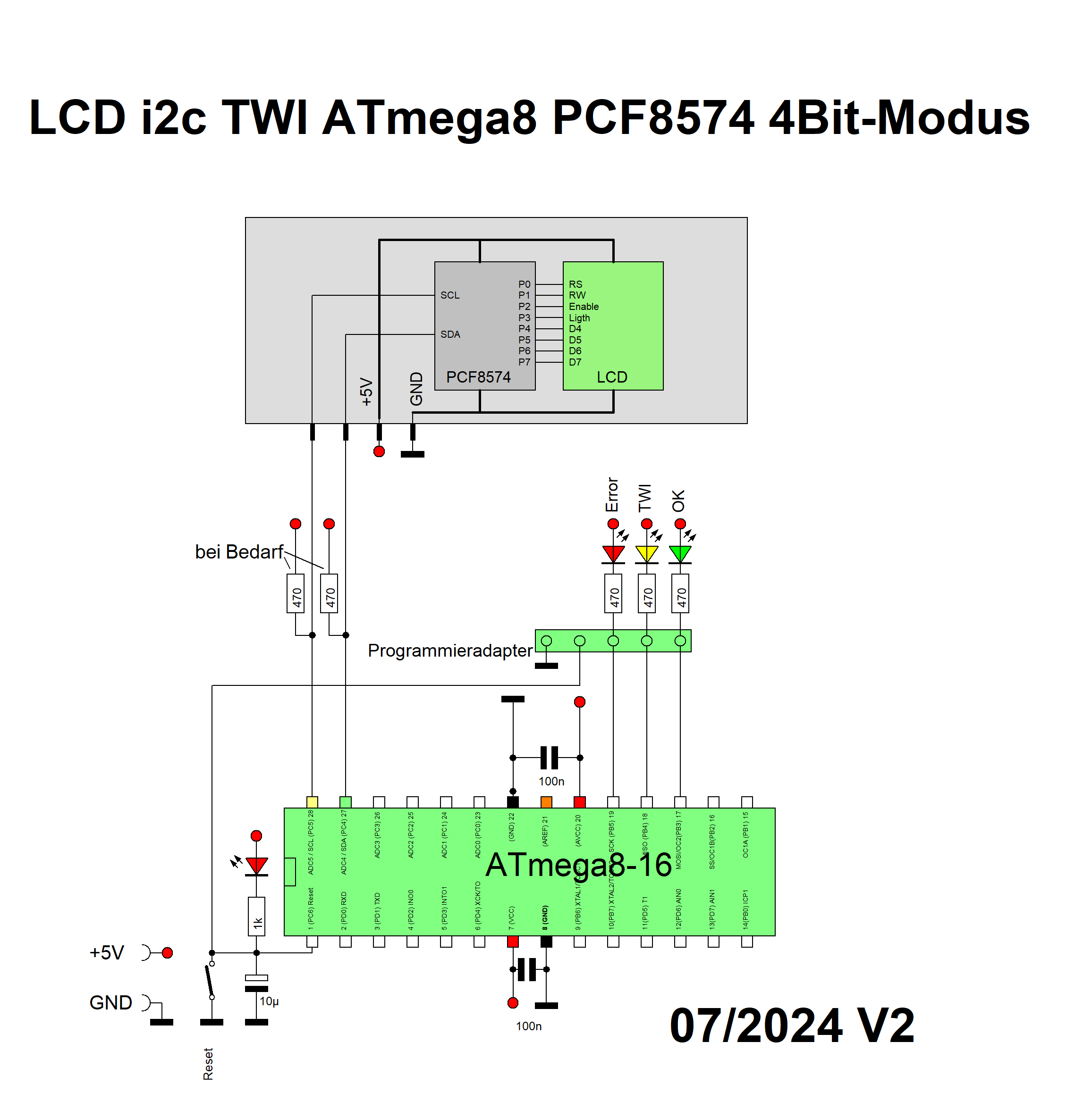
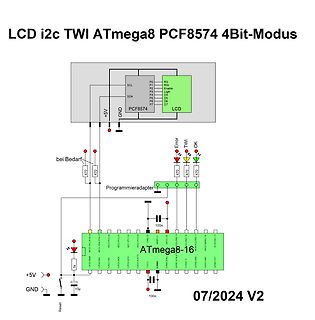
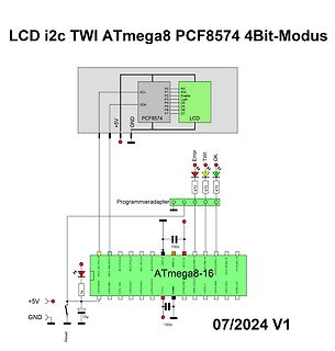
Schaltplan ATmega8 mit LCD und PCF8574 I2C-Adapter
LCD i2c TWI ATmega8 PCF8574 4Bit-Modus SCL SDA RS RW Enable Latch D4 D5 D6 D7 +5V GND PCF8574 LCD bei Bedarf 470 Error TWI OK 470 470 Programmieradapter 100n ATmega8-16 ADC0 ... ADC7 PB0 ... PB7 +5V GND 1k 10µ 100n Reset 07/
in „i2c TWI LCD 4Bit PCF8574 HD44780 ATmega8 Assembler“ · Projekte & Code · · Schaltpläne
-
Datei
test_i2c.c
* test_i2c.c * * Created: 05.07.2013 08:06:59 * Author: 84979fw */ #include <avr/io.h> #include "pcf8574.h" #define F_CPU 11059000 #include <util/delay.h> int main(void) { DDRB=0xFF; PORTB=0x00; char test; while(1) { test=pcf8574_get_inputs (2); PORTB=test; _delay_ms(1000); PORTB=0xFF; _delay_ms(1000
in „PCF8574N Daten lesen“ · Mikrocontroller und Digitale Elektronik ·
-
Datei
PCF8574AP.c
//Include H-TWI.c unsigned char pcf8574ap_readbyte(unsigned char addressout) { unsigned char xyz=0; xyz|=0b01110001; addressout=addressout<<1; xyz|=addressout; htwi_init (); htwi_start (); htwi_writebyte (xyz, 1); unsigned char input = htwi_readbyte (0); htwi_stop (); return input; } void pcf8574ap_writebyte(unsigned char addressout, unsigned char byte) { unsigned char xyz=0; xyz|=0b01110000; addressout=addressout<<1; xyz|=addressout; htwi_init (); htwi_start (); htwi_writebyte (xyz, 1); htwi_writebyte
in „Problem LCD über PCF8574AP ansteuern“ · Mikrocontroller und Digitale Elektronik ·
-
 Bild
Bild
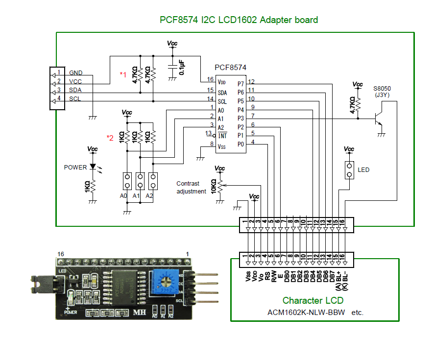
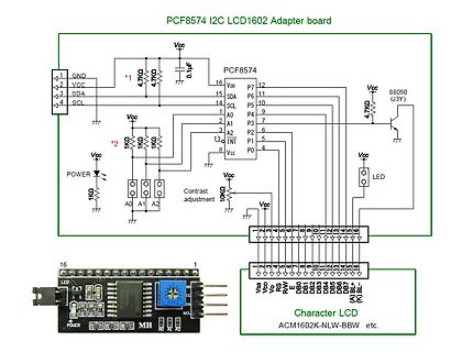
Schaltplan und Foto eines PCF8574 I2C LCD Adapter boards
PCF8574 I2C LCD1602 Adapter board Vcc GND SDA SCL A0 A1 A2 PCF8574 VDD P7 P6 P5 P4 P3 P2 P1 P0 INT S8050 4.7k Vcc Contrast adjustment 10k A0 A1 A2 1k 1k 0.1uF LED Character LCD ACM1602K-NLW-BBW etc. Vss V0
in „HD44780 I2C Adapter“ · Mikrocontroller und Digitale Elektronik · · Schaltpläne
-
 Bild
Bild
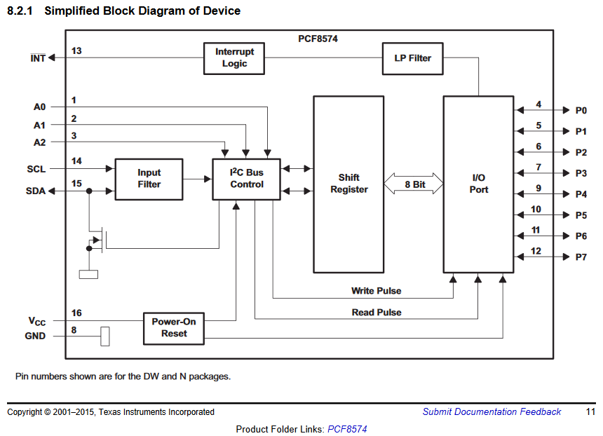
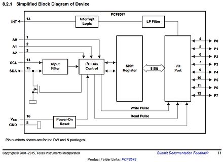
Blockschaltbild des PCF8574 ICs
8.2.1 Simplified Block Diagram of Device PCF8574 INT 13 Interrupt Logic LP Filter A0 1 A1 2 A2 3 SCL 14 SDA 15 I2C Bus Control Shift Register 8 Bit I/O Port P0 4 P1 5 P2 6 P3 7 P4 9 P5 10 P6 11 P7 12 VCC 16 GND 8 Power-On Reset Write Pulse Read
in „I2C-Bus: SDA und SCL an ATMEGA328p“ · Mikrocontroller und Digitale Elektronik · · Diagramme
-
 Bild
Bild
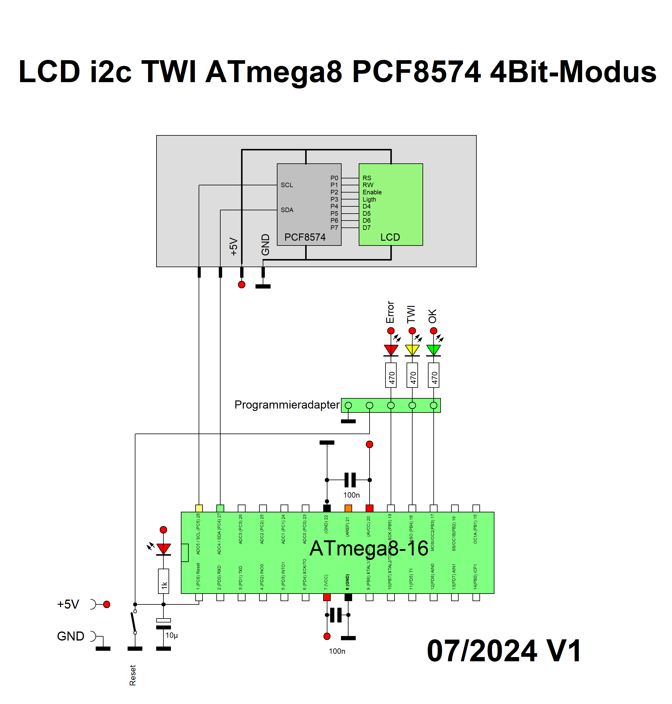
Schaltplan ATmega8 mit PCF8574 und LCD-Ansteuerung
LCD i2c TWI ATmega8 PCF8574 4Bit-Modus P0 RS P1 RW P2 Enable P3 Light P4 D4 P5 D5 P6 D6 P7 D7 SCL SDA +5V GND PCF8574 LCD Error TWI OK 470 470 470 Programmieradapter 100n AD0 A5 I2C SDA P25 AD1 A4 I2C SCL P24 AD2 A3 I2C P23
in „i2c TWI LCD 4Bit PCF8574 HD44780 ATmega8 Assembler“ · Projekte & Code · · Schaltpläne
-
 Bild
Bild
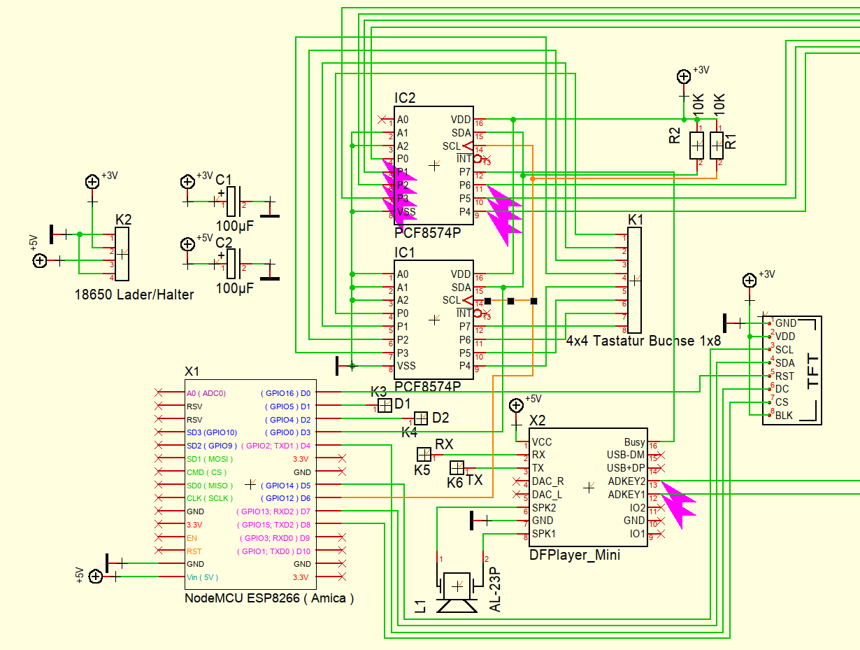
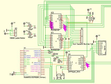
Schaltplan mit NodeMCU ESP8266 und PCF8574 I/O Expander
IC2 PCF8574P A0 A1 A2 P0 P7 P6 P5 VSS VDD SDA SCL +3V R2 10K R1 10K C1 100µF C2 100µF K2 +5V 18650 Lader/Halter K1 K3 PCF8574P D1 D2 K4 RX RX TX TX DAC_R DAC_L SPK2 SPK1 X2 VCC USB-D USB+ GND IO2 GND IO1 K5 K6
in „ESP8266 mit SPI Display und DF Player“ · Mikrocontroller und Digitale Elektronik · · Schaltpläne
-
Datei
i2c-lcd.c
#include "i2c.h" #include "help.h" #include "pcf8574.h" #define RS 0x05 #define RW 0x06 #define E 0x07 #define DISP_ON 0x0c //LCD control constants #define DISP_OFF 0x08 // #define CLR_DISP 0x01 // #define CUR_HOME 0x02 // #define SENDTOLCD write_pcf8574
in „LCD (4bit-mode) am PCF8574“ · Mikrocontroller und Digitale Elektronik ·
-
PDF
84123_usb_i2c_handbuch_v1_7.pdf
den hier gegebenen Beispielen schnell verwendet werden können. 4.5.1. 8-Bit I/O-Interface mit dem PCF8574 Der 8-Bit-I/O-Expander Baustein PCF8574 von Texas Instruments bzw. NXP ist ein sehr universeller Schalt- kreis, der für erste Experimente und für viele Anwendungen ideal ist. Eine Beispielsschaltung
in „Hygrosens I2C Tmp Modul antwortet nicht“ · Mikrocontroller und Digitale Elektronik ·
-
Datei
txlcd_i2c_demo.c
------------------ txlcd_i2c_demo.c Anbindung eines HS44780 kompatiblen Textdisplays ueber einen PCF8574 I2C I/O Expander MCU : ATtiny44 F_CPU : 8 MHz intern Fuses : fuer 8 MHz intern lo 0xe2 hi 0xdf Fuses : fuer ext. Quarz >= 8 MHz lo 0xde hi 0xdf Pinbelegung I2C --------------- PB0 = SDA PB1 = SCL
in „(sehr) kleines "FrameWork" für ATtiny44“ · Projekte & Code ·
-
Datei
twi_send.c
void Send_Address(TWI_t *twi, char Adresse) { twi->MASTER.ADDR = Adresse; _delay_us(500); } void PCF8574_send_byte(TWI_t *twi, char Adresse, char byte) { Send_Address(twi, Adresse); twi->MASTER.DATA = byte; } void Int_init(void) { PMIC.CTRL |= PMIC_LOLVLEN_bm | PMIC_MEDLVLEN_bm | PMIC_HILVLEN_bm; //
in „XMega I2C/TWI mit AVR-GCC“ · Mikrocontroller und Digitale Elektronik ·
-
Datei
LCD_PCF8574-dotmatrix_7219--learn.asm
/* * LCD_PCF8574_dotmatrix_7219__learn.asm * * Created: 26.11.2014 12:28:23 * Author: Killroymenzel */ .nolist #include "m128adef.inc" .list /************************************************ * Register definition
-
Datei
mega8.asm
*************************************** ;ATMega8 & I²C - Testprogramm ; ;Hardware: ;- ATMega8 ;- PCF8574 mit 8 Tastern & Pullups (Adresse 0b01000010) ;- PCF8574 mit 8 LEDs (Adresse 0b01000000) ;*********************************************************** .include "m8def.inc" .def temp=r16 .def byte=r22
in „Mega8 und Software I2C“ · Mikrocontroller und Digitale Elektronik ·
-
Datei
lcd_i2c.c
for the display is included as PDF file. * Software assumes a 4x20 Display, connected to I2C by a PCF8574 with Adr. 66. * * (C) 2003 www.Wickenhaeuser.com * */ #include <stdio.h> #include "lcd_io.h" // Re-declare Low level routines as REENTRANT for use in lcd_printf() extern uint i2c_selectslave(uchar
in „LCD-Ansteuerung mit PCF ?“ · Mikrocontroller und Digitale Elektronik ·
-
PDF
LCD-I2C.pdf
e L R t t t t t t A B B B B B B A X4 6Pin Tasten 30 - 500 1 2 3 4 5 6 1 D CD4051 470-1050 D A 11 PCF8574 Low 1,5V V 10 B 100 µA * 2000 = 0,2 V C 9 13 X0 14 X1 X 3 15 6 X2 INH 12 X3 1 X4 5 X5 IN7 2 X6 S E IN8 4 X7 S E V V 8 7 CD4051B IC2 X1 a2 b2 RS 1 2 RW EN 3 4 BtUp Button B B BtDown 5 6 BtLeft BtRight
in „Pollin Display HB10401“ · Mikrocontroller und Digitale Elektronik ·
-
Datei
I2C.c
verschieben (für r/w bit) addr_byte |= rw; //r/w bit hinzufügen addr_byte |= 0b01000000; //Aresscode vom PCF8574 (1. 4 Stellen = 0100 siehe Datenblatt) TWDR = addr_byte; //Adresse senden TWCR = (1 << TWINT) | (1 << TWEN); //Clear TWINT bit in TWCR to start transmission of address while(!(TWCR & (1 << TWINT))
in „PCF8574 über I2C“ · Mikrocontroller und Digitale Elektronik ·
-
PDF
BFE_AG_Di_230_Dot_Matrix.pdf
1 2 3 4 5 6 7 8 5V 5V IC3 PCF8574 IC5C P0 PIIC501 PIIC5016 I4 IC8A8B P1 PIIC502A VCC PIIC802 PR PIIC805N74AHC74D A P2 3 B 15 D Q o o o o o o o o o o A P3 PIIC503C Y0 PI145015 3 P4 PIIC506 Y1 PIIC5013 PIIC803CLK P5 4 OE1 Y2 12 6 P6
in „[V] #VERKAUFT# Platine mit 8 Stück DLG7137, 5*7 Punktmatrix“ · Markt ·
-
PDF
BFE_AG_Di_230_Dot_Matrix.pdf
1 2 3 4 5 6 7 8 5V 5V IC3 PCF8574 IC5C P0 PIIC501 PIIC5016 I4 IC8A8B P1 PIIC502A VCC PIIC802 PR PIIC805N74AHC74D A P2 3 B 15 D Q o o o o o o o o o o A P3 PIIC503C Y0 PI145015 3 P4 PIIC506 Y1 PIIC5013 PIIC803CLK P5 4 OE1 Y2 12 6 P6
-
Datei
PIC_41__2-06_.asm
; Programm LCDEXP0.asm: Demoprogramm für LCD-Modul, angesteuert über Expander PCF8574 ; PIC 16F84, f = 4 MHz, SC = 1us; OUT(sda) an RA0, CLOCK(scl) an RA1, CS an RA2 ; Dieter Kohtz, Juni 2005 ;*****************************************************************************************
in „LCD am I2C initialisieren“ · Mikrocontroller und Digitale Elektronik ·
-
 Bild
Bild
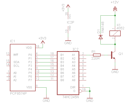
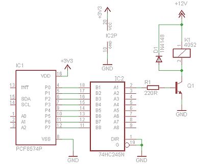
Schaltplan mit PCF8574P und 74HC245N
12, B7, A7, 8, A0, 1, A1, 2, A2, 3, P7, 12, 11, B8, A8, 9, VSS, 8, IC2, DIR, 1, G, 19, 74HC245N, PCF8574P
in „Lichtsteuerung über i2c - ULN2803A - S12-100“ · Mikrocontroller und Digitale Elektronik · · Schaltpläne
-
PDF
HTerm_PCF8574.pdf
HTerm_PCF8574.pdf
in „ELV USB-I2C Interface und H Therm“ · Mikrocontroller und Digitale Elektronik ·
-
Datei
i2c.h
///////////////////////////////////////////////////////////////////////////////////////////// // PCF8574 (Remote 8-bit I/O expander) /////////////////////////////////////////////////////////////////////////////////////////////////// #define I2C_ADDR_PCF8574 0x20 // 00100AAA #define CHANNEL_1 0x01 #define
in „MSP430F2370 I2C“ · Mikrocontroller und Digitale Elektronik ·
-
Datei
i2c.h
///////////////////////////////////////////////////////////////////////////////////////////// // PCF8574 (Remote 8-bit I/O expander) /////////////////////////////////////////////////////////////////////////////////////////////////// #define I2C_ADDR_PCF8574 0x20 // 00100AAA #define CHANNEL_1 0x01 #define
in „I2C Ansteuerung von PCA9685 mit MSP430“ · Mikrocontroller und Digitale Elektronik ·
-
Datei
LCD_Ausgabe_TWI_USI.asm
LCD Self-Reset abwarten rcall twistart ldi temp, 0x70 ; Slave Startadresse + RW-Bit rcall twiout ; PCF8574->0x40; PCF8574A->0x70 rcall lcd_achtbitinit ; LCD-Init: acht Bit rcall lcd_acht_vier ; LCD-Init: acht zu vier Bit rcall lcd_vier_zwei_z ; LCD-Init: vier Bit, 2 Zeilen rcall lcd_on_off ; LCD-Init:
in „RE Bit Display EA DIP204-4 (KS0073)“ · Mikrocontroller und Digitale Elektronik ·
-
Datei
mcp23017_2.c
/ MCP23017_send_add_rw (address, 1); //Adresse senden und Lesen einstellen unsigned char input = pcf8574_read_byte (); MCP23017_send_stop (); return input; } void MCP23017_set_outputs (unsigned char address, unsigned char byte) { // MCP23017_init (); MCP23017_send_start (); // MCP23017_send_add_rw (address
in „I2C - Pull Up Widerstände“ · Mikrocontroller und Digitale Elektronik ·
-
PDF
lalus.pdf
MFV-Gebers. DTMF- zeigt die Organisation des spre- Geber II 010. II VO- 8 II * Expander * Schalter y (PCF 8574) Postleitung ii ELECTRONIC ACTUELL Magazin 8/97 3 frage geht, dann meldet er das artig Die Blockschaltung Triggersign8\ retriggerbares vom Prozessor mit ,,Temperatur”, gefolgt von den Auf der Grafik
in „Schaltung an a/b - Port (Telefonanlage) anbinden“ · Mikrocontroller und Digitale Elektronik ·
-
Datei
LCD_Init_USI.asm
power on self reset rcall twistart ldi temp, 0x7E ; slave start adresse + RW-Bit rcall twiout ; PCF8574->0x40..4E; PCF8574A->0x70..7E rcall lcd_eight_bit ; LCD-Init: eight bit rcall lcd_eight_four ; LCD-Init: eight to four bit change rcall lcd_four_two_r ; LCD-Init: four bit, 2 rows rcall lcd_on_off
in „AVR-Tutorial: LCD - Erweiterung lcd-routines.asm - Bitte um Feedback“ · Mikrocontroller und Digitale Elektronik ·
-
Datei
I2C.c
include "xc.h" #include "stdio.h" #include "stdarg.h" #include "stdlib.h" #include "I2C.h" #define PCF8574_ADDR_WRITE 0x70 #define PCF8574_ADDR_READ 0x71 //local functions: char i2c_read_ack(void); unsigned char I2Cpoll(char addr); //I2C int kI2CBaud = 38; //I2C Baudrate Equation 17-1 (100kBd) /*init I2C
in „I2C PIC 18F2550 und MCP4728“ · Mikrocontroller und Digitale Elektronik ·
-
Datei
main.asm
Daten von DS18B20 oder DS18S20 im 5 Sekunden-Takt. Die Daten werden umgerechnet und per I2C über PCF8574 zum LCD1602/2004 übertraben. Line1: Anzeige DS18B20 oder DS18S20 (und im Fehlerfall der Code angezeigt). Line2: Temperatur -55,000 125,000°C. Taste: ca. 2 Sekunden ROM-, dann ca. 2 Sekunden RAM-Daten
in „AVR ATtiny13 DS18B20/DS18S20 I2C PCF8574 LCD Temperaturanzeige“ · Projekte & Code ·
-
PDF
I2C-Platine-LCD_von_Pollin.pdf
2-polig 3 JP1, JP2, JP3Stiftleiste 1x3-polig mit Bestückungsplan Codierbrücken 1 Q1 BC327 1 IC1 PCF8574P 1 Platine Stückliste 2 Widerstände: Um mit der Montage derWiderstände beginnen zu können, muss zunächst ermittelt werden, welchenWert jeder einzelne Widerstand besitzt, um ihn so anschließend an
in „I2C und LCD mit der Pollin.Lib in Bascom“ · Mikrocontroller und Digitale Elektronik ·
-
Datei
LCD_I2C_01.asm
HD44780 compatible ; P7 P6 P5 P4 P3 P2 P1 P0 ; D7 D6 D5 D4 LED ENA R|W RS ; Device slave address: $38 (PCF8574A) ;ATtiny2313 memory use summary [bytes]: ;Segment Begin End Code Data Used Size Use% ;[.cseg] 0x000000 0x000318 722 70 792 2048 38.7% ;[.dseg] 0x000060 0x000060 0 0 0 128 0.0% ;[.eseg] 0x000000 0x000000
in „I2C Display einfache Frage“ · Mikrocontroller und Digitale Elektronik ·
-
Datei
T6963c.h
#define T6963C_TEXT 0x04 #define T6963C_GRAPHIC 0x08 #define T6963C_TEXT_GRAPHIC 0x0C void writePCF8574A(uint8_t cmd, unsigned char data); unsigned char readPCF8574A_DATA(); //Sets Port & Initializes T6963c void T6963cInit(uint8_t Options, uint8_t Mode); //Set Cursor-Pattern void T6963cCursorPattern
in „Frage zu SPI und MCP23S09“ · Mikrocontroller und Digitale Elektronik ·
-
Datei
SainSmart_USI_27022026.asm
HD44780 compatible ; P7 P6 P5 P4 P3 P2 P1 P0 ; D7 D6 D5 D4 LED ENA R|W RS ; Device slave address: $38 (PCF8574A) ;ATtiny4313 memory use summary [bytes]: ;Segment Begin End Code Data Used Size Use% ;[.cseg] 0x000000 0x00031c 726 70 796 4096 19.4% ;[.dseg] 0x000060 0x000060 0 0 0 256 0.0% ;[.eseg] 0x000000 0x000000
in „HD44780 I2C Adapter“ · Mikrocontroller und Digitale Elektronik ·
-
PDF
Spec_Inkontinenzsensor_ATtiny461A.pdf
0010 .. + xxx + R/W ATtiny261 analog 8-F 0011 0x18 24 0x30 48 .. + xxx + R/W ATtiny261 binär 8-F PCF8574, Broadcastadress: 0x20 32 0x40 64 0100 .. + xxx + R/W PCF8574 Subadr=000 0x28 40 0x50 80 0101 .. + xxx + R/W MAX127 ATtiny461 0-7 ATtiny461A 0-7 0x30 48 0x60 96 0110 .. + xxx + R/W MAX1236 ATtiny461 8-F ATtiny461A 8-F 0x38 56 0x70 112 0111 .. + xxx + R/W PCF8574A 1000 0x40 64 0x80 128 .. + xxx + R/W 0x48 72 0x90 144 1001 .. + xxx + R/W ATtiny26 analog 0-3, PCF8591, PCF8591, LM75, 0x50 80 0xA0 160 1010 .. + xxx + R/W LM75, DS1631 DS1631 ATtiny261 analog 0-
-
Datei
Angaben.txt
Implementation ;*** Function: Implementaion of I2C-Bus with connection to a ;*** 1. I/O-Extension PCF8574 ;*** 2. DSM-0822a ;*** Author: Andreas Hesse ;*** Date of construction: 2003-04-09 ;*** Date of last revision: 2003-11-16 ;*** Version: 1.0.1.0 ;*** Target: AT90Sxxxx (any AVR device) ;*** Comment
in „Crashkurs in Sachen I²C-Bus“ · Mikrocontroller und Digitale Elektronik ·
-
Datei
LCD_TWI.asm
TESTPROGRAMM ################################################ ; TWI HARD-ware ATmega8A ; LCD_TWI mit PCF8574 ;######################################################################################### .nolist .include"m8adef.inc" ;Professor wählen .list .equ F_CPU = 8000000 ; Systemtakt in Hz ;--- Statusregisterinhalt
in „RE Bit Display EA DIP204-4 (KS0073)“ · Mikrocontroller und Digitale Elektronik ·
-
PDF
Ausgangsstufen_Logic_IC.pdf
aufgenommen werden. Bei HIGH können nur sehr geringe Ströme entnommen werden, siehe Port-Expander PCF8574. Der Widerstandswertes des Pull-up-Widerstands darf nicht zu groß gewählt werden, da sonst zusammen mit Eingangs- und parasitären Kapazitäten die Signale verschleifen und im Extremfall nicht mehr
in „Wittig(welec) DSO W20xxA Open Source Firmware (Teil3)“ · Mikrocontroller und Digitale Elektronik ·
-
PDF
PCF8574_RelayBoard.pdf
PCF8574_RelayBoard.pdf
in „PCF8574 Ausgänge puffern bis 42V“ · Mikrocontroller und Digitale Elektronik ·
-
Datei
CAN_MCP2515-test2.bas
pins Spiinit '--------------------------Für I2C LCD ----------------------------------------- Const Pcf8574_lcd = 112 'PCF Adresse für LCD (original Pcf8574_lcd =70) $lib "Lcd_i2c.lib" 'I2C Treiber für das LCD Dim _lcd_e As Byte 'Um auch LCDs mit 2 Controllern 'nutzen zu können. _lcd_e = 128 'Für LCDs mit
in „MCP2515 mit BASCOM“ · Mikrocontroller und Digitale Elektronik ·
-
PDF
BFE-Di_230_schematic.pdf
1 2 3 4 5 6 VCC R27 J1_SCL 47k J1_SDA 47k J1_A1 R28 J1_A2 J1_~{INT} A A VCC VCC U2 U3 VCC VCC 6 PCF8574 6 PCF8574 U5 1 1 1 74HC138 D D 14 V 4 14 V 4 1 15 SCL P0 DISP_D0 SCL P0 A0 C O0 15 SDA P1 5 15 SDA P1 5 2 A1 V O1 14 6 DISP_D1 6 3 13 BAR_FF_CLK P2 DISP_D2 P2 A2 O2 1 A0 P3 7 DISP_D3 1 A0 P3 7 O3
-
PDF
BFE-Di_230_schematic.pdf
1 2 3 4 5 6 VCC R27 J1_SCL 47k J1_SDA 47k J1_A1 R28 J1_A2 J1_~{INT} A A VCC VCC U2 U3 VCC VCC 6 PCF8574 BAR_FF_STATE1 6 PCF8574 U5 1 BAR_FF_STATE2 1 1 74HC138 D D 14 V 4 14 V 4 1 15 SCL P0 DISP_D0 SCL P0 A0 C O0 15 SDA P1 5 15 SDA P1 5 2 A1 V O1 14 6 DISP_D1 6 3 13 BAR_FF_CLK P2 DISP_D2 P2 A2 O2 1 A0
-
PDF
I2CselectionGUIDE.pdf
bit I/O expander 0 A1 A0 SAA1300 Tuner switch circuit A2 A1 A0 TDA8444 Octuple 6-bit DAC A2 A1 A0 PCF8574 8-bit remote I/O port (I C-bus to parallel converter) 1 0 A0 PCD3311C DTMF/modem/musical tone generator 1 0 A0 PCD3312C DTMF/modem/musical tone generator 1 1 1 PCD5002 Pager decoder 1999 Aug 24 16
in „Übersicht I2C-Adressen“ · Mikrocontroller und Digitale Elektronik ·
-
Datei
i2clcd.c
************** i2clcd.c - LCD over I2C library Designed for HD44870 based LCDs with I2C expander PCF8574X on Atmels AVR MCUs Copyright (C) 2006 Nico Eichelmann and Thomas Eichelmann 2014 clean up by Falk Brunner This library is free software; you can redistribute it and/or modify it under the terms of
in „Tastenentprellung seltsames Phänomen“ · Mikrocontroller und Digitale Elektronik ·
-
PDF
Readme_130816.pdf
TWI-Luftdruck-/Temperatursensor auslesen srf02.py - TWI-Ultraschall-Entfernungsmesser SRF02 auslesen pcf8574.py - TWI-Portexpander PCF8574 Pins setzen pcf8583.py - TWI-RTC Uhrzeit einstellen und auslesen adxl345.py - TWI-Beschleunigungssensor ADXL345 auslesen Beschreibung der Arbeitsweise des Programms auf
-
Datei
i2clcd.c
************** i2clcd.c - LCD over I2C library Designed for HD44870 based LCDs with I2C expander PCF8574X on Atmels AVR MCUs Copyright (C) 2006 Nico Eichelmann and Thomas Eichelmann 2014 clean up by Falk Brunner This library is free software; you can redistribute it and/or modify it under the terms of
in „Probleme mit meinem LCD-Display“ · Mikrocontroller und Digitale Elektronik ·
-
PDF
PA100D.pdf
P7 12 T T T T T R16 D 1 2 D 1 2 D 1 2 D 1 2 D 1 2 C VSS 8 S S S S S C C 3 4 3 4 3 4 3 4 3 4 C V PCF8574T GND GND STBY/OPER GND 22-27-2021-02 IC13 X1-2 7 6 VDD 16 C17 4 R ATT 13 INT P0 4 LED1_RT 22-27-2021-02 100n P1 5 LED1_GN X2-1 15 SDA P2 6 LED2_RT X2-2 14 SCL P3 7 LED2_GN C 1 P4 10 C 2 A0 P5 11 V GND GND 3 A1 P6 12 D A2 P7 150 D 8 RTC, Taster/Schalter und LEDs (C) 2015 DJ2AT VSS LED_DBG R48 PCF8574T LSR976-NR-1-Z GND GND 1 2 3 4 5 6 1 2 3 4 5 6 2 + A A 1 RN1 10k JP3 1 160m 2 3 4 5 6 7 8 9 IC7 2 80m MOSI 14 SER QA 15 1 I1 O1 20 3 40m QB 1 2 I2 O2 19 4 30m SCK 11 SCK QC 2 3 I3 O3 18 /RESET 10
in „Schutzbeschaltung Analog-Eingänge / Durchsicht Schaltplan“ · Mikrocontroller und Digitale Elektronik ·
-
PDF
notes_82b96.pdf
peripheral chip that has been uniquely selected. Sub-addressing by means of port expander chips like PCF8574 has been widely used in telephone exchange systems. In this case the A0/A1/A2 pins of other I2C chips are modified by first writing one data word into several PCF8574s which shared one common I2C
in „18 x SHT11 an welchem Mikrocontroller“ · Mikrocontroller und Digitale Elektronik ·
-
PDF
notes_82b96.pdf
peripheral chip that has been uniquely selected. Sub-addressing by means of port expander chips like PCF8574 has been widely used in telephone exchange systems. In this case the A0/A1/A2 pins of other I2C chips are modified by first writing one data word into several PCF8574s which shared one common I2C
in „I²C galvanisch trennen“ · Mikrocontroller und Digitale Elektronik ·
-
PDF
Schrittmotor.pdf
. Der I2C – Bus erfüllt hier die Anforderungen an die Steuerung. Als Hardware benötigt man einen PCF8574 (I/O – Expander) und einen Motortreiber, z.B. den ULN2803A, der oben bereits beschrieben ist. Da die I2C – Routinen bereits im Lallusprogramm implementiert sind, bläht sich der Programmcode auch nicht
in „schrittmotor Steuerung“ · Platinen ·
-
Datei
prog.c
Registers definitions #include <io.h> #include <delay.h> #include <stdio.h> #include <twix.h> #define PCF8574_ADDR 0x38 unsigned char pcf_value_a=0x55; unsigned char pcf_value_b=0xAA; // System Clocks initialization void system_clocks_init(void) { unsigned char n,s; // Optimize for speed #pragma optsize-
in „Codevision CodeWizardAVR TWI Probleme“ · Mikrocontroller und Digitale Elektronik ·