F10 when the monitor light turns green to access the utility. You can also press Esc to a menu that allows you to access different options available at startup, including the Computer Setup utility. NOTE: If you do not press F10 at the appropriate time, you must restart
Zusätzlich muß die Interrupttabelle angepaßt werden auf den "neuen" µC. beispielsweise sieht diese beim At13 so aus: If the program never enables an interrupt source, the Interrupt Vectors are not used, and regular program code can be placed at these locations. The most typical and general program setup
. See page 10 for the different addressing modes. EEPROM Data Memory The AT90S2313 contains 128 bytes of EEPROM data memory. It is organized as a sep- arate data space in which single bytes can be read and written. The EEPROM has an endurance of at least 100,000 write/erase
this, select the and total runtime of the „Overheated Alarm battery. Switch“ fjeld. • - Settings You can illuminate You will fjnd the at the battery’s charge the top right after you level indicator using have selected the bat- the „Battery identifj- tery. 48 GB MT Press the icon again The battery can also
durchaus auch > einer Erwähnung bei den RAM-less AVRs wert sind. Historisch halt, genauso wie AT90S1200 und ATmega103, der dann ziemlich schnell einen ATmega128 als Nachfolger bekam. Dieser wiederum wurde zum „Dauerbrenner“, der wird als ATmega128A sogar zwei Jahrzehnte später noch produziert.
sec.............................................T.........Data Setup Time 50 ns Relative Humidity at 85°C.................................................................. 85% Maximum Number of LEDs on at 100% Brightness ............................128SDCLK Clock Period 200 ns Maximum Power Dissipation
IO-Link remains stable and has been growing continually for years, with more than 61 million nodes at last count. IO-Link continues to successfully establish itself as a global standard. PROFIsafe This kind of trend can also be seen with PROFIsafe nodes. Following exceptional growth in the preceding
BD35F-HD and BD1.4F-VSD-HD are new versions the need for current batteries if an ice bank is used which can handle extreme vibrations. for energy storage.When storing the sun energy in ice packs the cabinet can be kept at desired BD35F-B (Bus-optimized) temperatures both night and day. The BD35F-B is a special
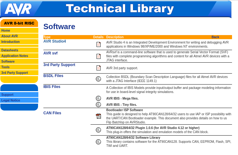
3rd Party Support
Support
Legal Notice
AVR Studio4
AVR svf
3rd Party Support
BSDL Files
iBIS Files
CAN Files
AVR 3rd party support.
Collection BSDL files for all Atmel AVR devices with a JTAG interface (IEEE 1149.1)
A Collection of IBIS Models
AVR IBIS - Mega files.
AVR IBIS - Tiny files.
Bootloader ISP Software
AT90CAN128/64/32 Software Library
modes, to keep track of time. It can wake up the device from sleep modes and/or interrupt the device at regular intervals. The reference clock is typically the 32.768 kHz output from an external crystal. The RTC can also be clocked from
Hallo, ich bin auf der Suche nach einer Fassung für den AT90CAN128. So, wie die hier https://www.reichelt.de/de/de/shop/produkt/ic-fassung_68-polig_plcc-14703 Allerdings in 64-polig. Bei meiner Suche finde ich nur 68-polig. Weiss jemand, wo ich die
Den AT90CAN128 gibt es auch im QFN-Gehäuse. Die sind deutlich stabiler, also müssten die Sockel eigentlich einfacher sein. Naja, Textool hat 2 verschiedene für 0.4mm-Pitch und scheinbar keinen für 0.5mm. Muss
CARD_POWER 1 G N D 20 FG1 DIR G LOW = Power OFF FG2 TC74VHCT245AFT SCAB1A8100 R255 1 IC94B 100k HD74LV32AT D IC90C IC90D RPC05T@J D 5 CARD_XBUSEN HD74LV00AT HD74LV00AT XCARD_BUS_ENABLE 6 RPC05T@J 9 12 XCA_IOIS16 4 R254 22 8 11 XIOIS16 10 13 RPC05T@J R256 NIU D +5 D +3.3 D LTLXBIG LTLXBIG R257 0 R258 NIU R259
5.9 13.0 9.0 7.7 15.0 13.8 11.2 15.0 15.0 13.7 (A) Peak Current (A) 63.5 30.1 24.9 89.0 44.9 37.0 90.0 64.0 54.1 90.0 73.7 58.9 Don’t see exactly what you need? Optional: Tachometer Specifications Still need help? Have ElectroCraft build you a Model Easily build your own motor at Tach Resistance Tach
CARD_POWER G N D FG1 1 DIR G LOW = Power OFF 20 FG2 0 TC74VHCT245AFT SCAB1A8100 R255 1 IC94B 100k HD74LV32AT D IC90C IC90D RPC05T@J D 5 CARD_XBUSEN HD74LV00AT HD74LV00AT XCARD_BUS_ENABLE 6 RPC05T@J 9 12 XCA_IOIS16 4 R254 22 8 11 XIOIS16 10 13 RPC05T@J R256 NIU D +5 D +3.3 D LTLXBIG LTLXBIG R257 0 R258 NIU R259
addition, there is a user range. User write to the memory is restricted to the NVM User Range. User read can also be performed to the other NVM addresses. 4.8.1 NVM User Range The host can write and read the memory of the user range. The range is located at addresses 0x20-0x22. Each address holds 2 bytes.
is enabled with ACC_CONF.acc_perf_mode=0b1. In this power mode, the accelerometer data is sampled at equidistant points in the time, defined by the accelerometer output data rate parameter ACC_CONF.acc_odr. The output data rate can be configured in one of eight different valid ODR configurations going
Zertifikation des Chips für diese schnellere Taktrate: [c] RP2040 has now been certified to run at a system clock of 200Mhz when using a regulator voltage of at least 1.15 volts. . . . With this version of the SDK, you can now select a 200Mhz clock for RP2040 simply by setting SYS_CLK_MHZ=200 via
> RP2040 has now been certified to run at a system clock of 200Mhz > when using a regulator voltage of at least 1.15 volts. > With this version of the SDK, you can now select a 200Mhz clock > for RP2040 simply by setting SYS_CLK_MHZ=200
dB 2 IIP3 Max Gain -11 dBm 3 IIP3 Min Gain +16 dBm F = 100.45 MHz, Local Oscillator phase noise LO -128 dBc/Hz Δf ≥ 1 MHz Local Oscillator Jitter 100 Hz – 150 kHz 0.2 º rms Notes: 1) Matched to 50 source 2) Two tones at 102 MHz & 104 MHz each of -40 dBm, LO at 100.45 MHz 3) Two tones at 102 MHz & 104
for the OSF flag to be set over the voltage range of 2.4V P V P VF . CC CCMAX 2 Note 15: The DS1308 can detect any single SCL clock held low longer thTIMEOUTMIN . The device’s I C interface is in reset state and can receive a new START condition when SCL is held low for at lTIMEOUTMAX . Once the part
. Audio applications can require a lot of wattage to drive loudspeakers. This implies a higher voltage rail than op amps commonly operate at. This and other high voltage applications can operate off of, and generate lethal
Microcontroller Component Details Supported boards ST STM32H747XI Processor Dual Core Arm® Cortex®-M7 core at up to All 480 MHz with double-precision FPU and 16K data + 16K instruction L1 cache Arm® 32-bit Cortex®-M4 core at up to 240 MHz with FPU, Adaptive real-time accelerator (ART AcceleratorTM) Flash Memory
isolation barrier: channel reinforced digital isolators with an integrated – >100-Year projected lifetime at 1 kV RMS high-efficiency power converter. The integrated DC- working voltage DC converter provides up to 650 mW of isolated power at high efficiency and can be configured – Up to 5000 V RMS isolation
D550 CAN BUS address is defined at 144 (or 0x90 in hexadecimal value). Figure 11 - EasyReg Advance CAN address configuration Note: D550 address change will be considered at product start-up only. For this example
N C M R 3 Physical Dimensions inches (millimeters) unless otherwise noted O C 0.114- 0.122 W 4 (2.90- 3.10) I 6 8 5 R 0 E 2 (4.16) Typ2) Typ M - S B 0.246- 0.256 (4.30- 4.50) y t (6.25- 6.5) (1.78) Typ c S h r 0.123- 0.128 (0.42) Typ o a (3.13- 3.30) (0.65) Typ n l 1 4 Land pattern recommendation o
Z_CLEARANCE_BETWEEN_PROBES * to avoid collisions during probing. * * Tune and Adjust * - Probe Offsets can be tuned at runtime with 'M851', LCD menus, babystepping, etc. * - PROBE_OFFSET_WIZARD (configuration_adv.h) can be used for setting the Z offset. * * Assuming the typical work area orientation: * -
. See page 10 for the different addressing modes. EEPROM Data Memory The AT90S2313 contains 128 bytes of EEPROM data memory. It is organized as a sep- arate data space in which single bytes can be read and written. The EEPROM has an endurance of at least 100,000 write/erase
Ihrem Controller passenden Pin-Num- mern zu ermitteln. HINWEISE, TIPPS! Einige AVR-Controller (z.B. AT90CAN32/64/128, ATMega64/128) haben spezielle Programmierpins PDI, PDO. Bitte benutzen Sie diese Leitungen anstatt MISO/MOSI (siehe Datenblatt). ERFOS-AVR-ISP unterstützt die adaptive SPI-Bitratenanpassung
and/or differential measurement techniques. Capacitive coupling offers a high level of integration at a relatively low cost. A potential disadvantage is that unwanted AC common-mode voltages can flow across the barrier; however, this can be easilymanaged because capacitance values arepicofarads or less
there are 128 resistors in a string N = N = between terminal A and terminal B. The wiper can be 256 128 set to tap onto any of these 128 resistors thus providing 129 possible settings (including terminal A and terminal
Oldies.... C stammt aus den 70ern, C++ aus den 80ern, AVR und der dazugehörige Assembler aus den 90ern, Rust aus den 2000ern. Also eigentlich hätte man AVRs direkt in C und C++ programmieren können, und jetzt sogar auch in Rust. ARM hat in den 80ern angefangen, und lässt sich natürlich auch super in
they figured that somebody was going to buy this processor to use for a company, and their company can pay a few thousand dollars in time-sharing charges to use an assembler that was available in time-share. I didn’t have any money like that, so a friend taught me that you just sort of look at each instruction
multiplexer and the converter can be developed separately from one another and optimized for e▯ciency and/or costs. Fifth, a power multiplexer can be implemented more easily if the switching process can be done at low frequency (10Hz
position, SET MASTER VR TO 0dBu OUT, EQ FLAT, W/20KHz LPF,A-WEIGHTED) 14-5 LR SEPARATION: MORE THAN 85dB AT 1KHz (TCD782 TRK2,9,11, GAIN VR 12:00 position, SET MASTER VR TO 0dBu OUT, EQ FLAT, W/20KHz LPF, A-WEIGHTED) 16. USB SLAVE PLAYER SECTION(Windows7 &Audacity-win-2.1.0): (SIGNAL FORMAT : MP3, 128KBPS)
are subject to change At 9 kHz: 35 dB without notice. At 10 kHz: 40 dB 5) You can change theAM tuning scale to 9 kHz or 10 kHz. After tuning in anyAM station, turn off the receiver. Hold down PRESET TUNING + and press ?/1 .
142 and Table 31, “Command Timing Parameters for the FM Receiver,” on page 144. FM: LO frequency is 128 kHz above RF for RF frequencies < 90 MHz and 128 kHz below RF for RF frequencies > 90 MHz. For example, LO frequency is 80.128 MHz when tuning to 80.00 MHz. Note: For FMRX components 2.0 or earlier,
recommended the LC material has the (R ROW / 2.7 + COM) x CROW < 0.8 S following characteristics: where (V90-V10/V10 = (VONV OFF)/VOFFx 0.72~0.80 l CROW : LCD loading capacitance of one row of pixels. It can where V 90d V 10are the LC characteristics, andON and LCD panel capacitance.ux-Rate, where C LCDis the
by setting GPIO_FUNCx_OUT_INV_SEL bit. 5.5.3 Simple GPIO Output GPIO matrix can also be used for simple GPIO output. This can be done as below: • Set GPIO matrix GPIO_FUNCn_OUT_SEL with a special peripheral index 128 (0x80); • Set the corresponding bit in GPIO_OUT_REG register
das merken, auch bei 16 MHz. Ich kann das sagen, weil ich vor etwa 20 Jahren ein Produkt mit einem AT90CAN128 (Mega128 plus CAN, VCC=5V) und einem ILI9321 (Vorvorgänger des ILI9341, Vio=2.8V) entwickelt habe. fchk
0x800500 -Wl,--defsym=__DATA_REGION_LENGTH__=32768[/c] angegeben werden. Dieselbe Software für den AT90CAN128 funktioniert aber auch mit der Version 4.3.3. Hier ist jedoch kein externer Ram angeschlossen und auch nicht beim Linken eingestellt, weil der genug internen hat. Es wird also Zeit, dass ich
software; you may redistribute it under the terms of the GNU General Public License version 3 or (at your option) a later version. This program has absolutely no warranty. [/pre] Schwieriger ist es für die AVR-LibC, da es für diese keine installierten ausführbaren Kommandos gibt. Hier musst du
bei mehreren Projekten im Internet zu finden. Ich habe lediglich die Timerinitialisierung für den AT90CAN128, ATMega162 und AT90S8515 geändert. Bei allen drei Controllern läuft es einwandfrei. Sowohl auf einem STK500 als auch STK200. Beim STK200 aber mit zusätzlichem RAM. Ausserdem ist es nur schwer
/c] Nach kurzem Nachdenken fiel mir auf, dass ich als Parameter beim Compiler und Linker "-mmcu=at90can128" angegeben hatte, die Software aber mittlerweile für den AT90CAN128 zu gross ist, was den Ram betrifft. Beim Compilieren für den ATMega2560 war die Meldung nicht. Das Ganze nochmal getestet
www.mikrocontroller.net/topic/244442#2683557 Da kann sich Günter jetzt mal reinwühlen. Da hat er zu tun bis er über 90 ist.
Hier der Grund, wieso es nur um "ein" Bit ging. "...By logic level at the input S you can change the polarity of the segment outputs accordingly to the displays with common anode or cathode. Logical One for common anode displays, logical Zero for common cathode displays
Warning The minimum timer period is one millisecond in MicroPython, whereas with Arduino code, it can easily be reduced to one microsecond. Timer performances are limited so that MicroPython can keep up with the pace.. Damit ist die Methode "Timer" aus "Machine" gemeint. Also fast sowas wie ein Abstraction
die Schnelle nicht finden, grad mal für ulab lässt sich für den ESP32 eine Aussage "passt in eine 128k factory partition" aufspüren. https://github.com/v923z/micropython-ulab
by setting GPIO_FUNCx_OUT_INV_SEL bit. 5.5.3 Simple GPIO Output GPIO matrix can also be used for simple GPIO output. This can be done as below: • Set GPIO matrix GPIO_FUNCn_OUT_SEL with a special peripheral index 128 (0x80); • Set the corresponding bit in GPIO_OUT_REG register

 Bild
Bild
 Bild
Bild