-
 Bild
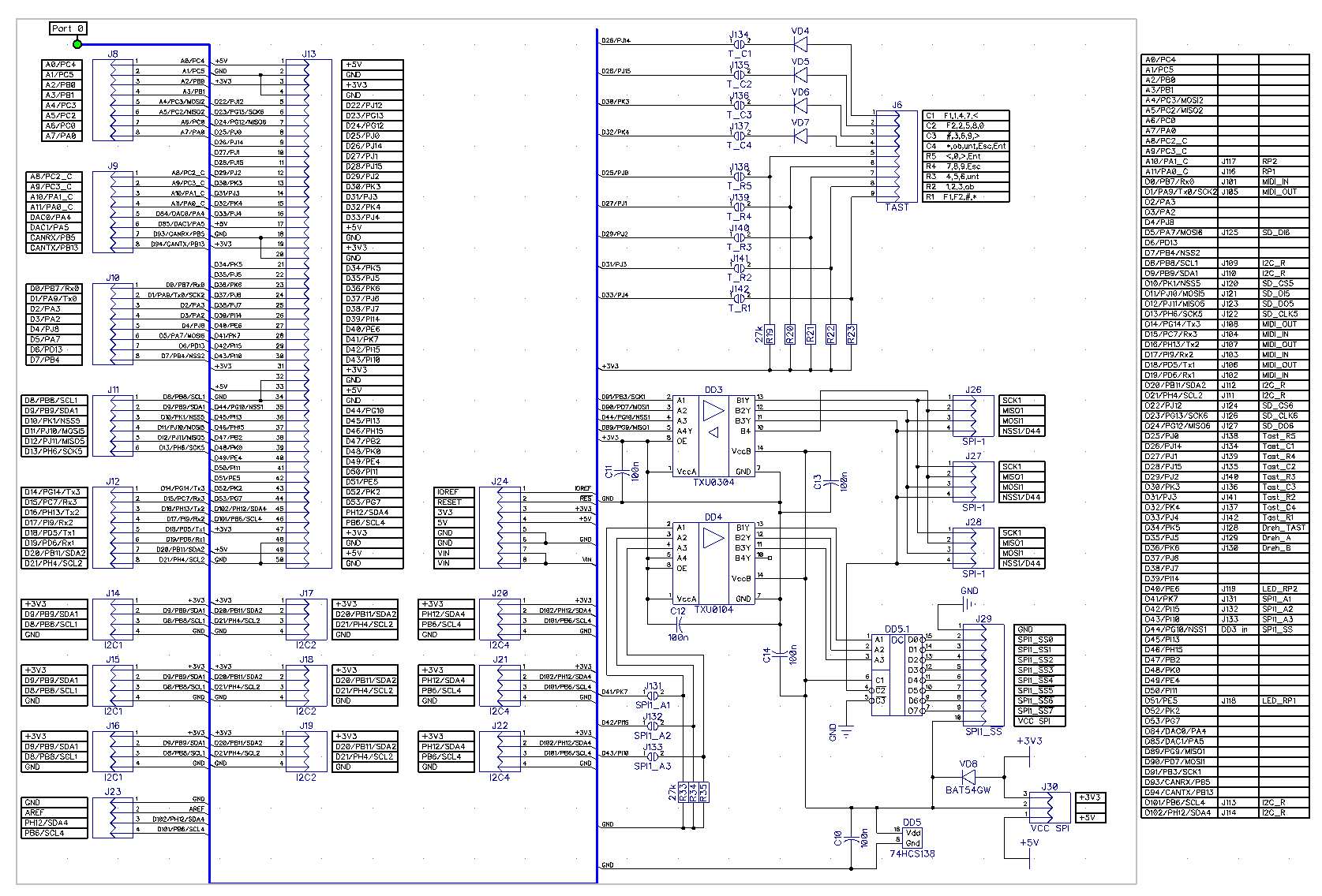
Schaltplan eines Mikrocontroller-Systems mit SPI und I2C
ATmega8, SPI, I2C, J13, J14, J17, J28, J24, J26, J34, J36, J38, J40, J42, J44, J46, J48, J50, J52, J54, J56, J58, J60, J62, J64, J66, J68, J70, J72, J74, J76, J78, J80, J82, J84, J86, J88, J90, J92, J94,
in „I2C Display einfache Frage“ · Mikrocontroller und Digitale Elektronik · · Schaltpläne
-
PDF
SCHALTPLAN_RADIO.pdf
SI4735 RDS Radio UKW LW MW KW ) V LCD 1 . ( s LCD164A LED +5V 1 t W C9 C10 s D n S / 0 1 2 3 4 5 6 7 16 V V K R R E D D D D D D D D 100n100µ GND 0 1 R MenueSENDER Programmieradapter 1 5 k k 1 1 SCL SI4735 SDA 8 7 6 5 4 3 2 1 0 9 8 7 6 5 r ) ) ) ) ) )
in „Si4735 RDS Radio UKW LW MW KW AM FM - TA TP AF GT TMC CT RT Pi PS ATmega8 Assembler“ · Projekte & Code ·
-
PDF
SCHALTPLAN_DCF77_1WIRE.pdf
DCF77 1-WIRE-SLAVE LCD 164A LED (4x16) t 0 1 s 16 2 t W s D on S / 0 1 2 3 4 5 6 7 10k V V K R R E D D D D D D D D 5V 1N4001 0,5V 0 1 10µ10n 10n10µ 7 4 DCF77 Programmier-Adapter FIN 36.11 5V 1 5 33µ 4 4 4 2 2 2 2 2 2 2 1 2 1
in „DCF / DCF77 UHR 1-WIRE / 1WIRE SLAVES / DEVICES ATmega8 ASSEMBLER“ · Projekte & Code ·
-
PDF
SCHALTUNG_VGA.pdf
VGA 640x480 (164x120) 7805 +12V GND 10µ 10µ 40 39 38 37 36 35 34 33 32 30 29 28 27 26 25 24 23 22 21 0 1 2 3 4 5 6 7 F D C 7 6 5 4 3 2 1 0 7 A A A A A A A A E N C C C C C C C C C D P P P P P P P P A G A P P P P P P
in „VGA 640x480 60Hz (164x120) RGB Vollgrafic ATmega1284p Assembler“ · Projekte & Code ·
-
Datei
TimerTest.cpp
avr/interrupt.h> #include <iopins.h> #include <pinlist.h> //#include <timer0.h> // OLD #include <ATmega-164-324-644-1284/Timer_local.h> // NEW using namespace Mcucpp; using namespace IO; using namespace Timers; //***************************************************************************** ISR(TIMER0
in „statische Memberfunktion als Interrupt-Handler?“ · Mikrocontroller und Digitale Elektronik ·
-
PDF
AVRDUDE-doc-5.5.pdf
2343 AT90S2343 (*) 4414 AT90S4414 4433 AT90S4433 4434 AT90S4434 8515 AT90S8515 8535 AT90S8535 m103 ATmega103 m128 ATmega128 m1280 ATmega1280 m1281 ATmega1281 m16 ATmega16 m161 ATmega161 m162 ATmega162 m163 ATmega163 m164 ATmega164 m169 ATmega169 m2560 ATmega2560 (**) m2561 ATmega2561 (**) m32 ATmega32 m324 ATmega324 m329 ATmega329 m3290 ATmega3290 m48 ATmega48 m64 ATmega64 Chapter 2: Command Line Options 4 m640 ATmega640 m644 ATmega644 m649 ATmega649 m6490 ATmega6490 m8 ATmega8 m8515 ATmega8515 m8535 ATmega8535
in „USB-ISP PRogrammer unter Ubuntu“ · PC Hard- und Software ·
-
Datei
boot.c
volatile("nop"); } while(1); } /* --------- do.bat --------- echo compile... avr-gcc -g -Os -mmcu=atmega16 -c boot.c echo link... avr-gcc -g -mmcu=atmega16 -Wl,-Map,boot.map,--cref,--section-start=.bootloader=0x1c00 -o boot.elf boot.o echo creating lst file... avr-objdump -h -S -d boot.elf > boot.lst
in „bootloader section in c“ · Mikrocontroller und Digitale Elektronik ·
-
Datei
KlimaSensorKomm.c
Taktsignal. Für weitere Infos siehe "12.2 - Ports as General Digital I/O" in der Beschreibung des ATMega32 #define SHT75_DATA_1 DDRC &= ~(1 << SHT75_DATA) //schreibt eine "1" auf den Bus (setzt den Pin hochohmig). Ein externer Pullup zieht den Bus auf High #define SHT75_DATA_0 DDRC |= (1 << SHT75_DATA
in „SHT75 - CRC Check: Ich finde den Fehler nicht“ · Mikrocontroller und Digitale Elektronik ·
-
Datei
dmx-pwm24.h
//#define DEBUG 1 #define TARGETXX4 1 // compile for ATmega164P/324P/664(P) #define PWM10BIT 1 // use 10 bit PWM #define DMX_SIZE 24 // number of used DMX channels #define BAUD 250000L // DMX512 #define F_CPU 20000000 // system clock in Hz #define F_PWM 100L
in „C - Ersatz von switch case.“ · Mikrocontroller und Digitale Elektronik ·
-
PDF
freq_zaehler_attiny.pdf
with this feature includes: Atmel ATtiny10, ATtiny13, ATtiny20, ATtiny26, ATtiny28, ATtiny2313, ATmega48/88/168, ATmega8, ATmega16, ATmega32, ATmega8515/8535, ATmega162, ATmega164/324/644/ 1284, and ATmega165/325/3250/645/6450. 2 AVR205 8365A-AVR-01/11 AVR205 Figure 2-2. Atmel ATtiny13A pinout. 3 Measurement
in „Frequenzzähler mit ATMega32“ · Mikrocontroller und Digitale Elektronik ·
-
PDF
device.pdf
) ADP-ATMEGA603-Q No Need WASIG V5.65 ATMEL MPU/MCU ATMEGA1280 ADP-ATMEGA128-Q100 No Need WASIG V5.65 ATMEL MPU/MCU ATMEGA1281(QFP64) ADP-ATMEGA603-Q No Need WASIG V5.65 ATMEL MPU/MCU ATMEGA128L(MLF64) ADP-ATMEGA128
-
Datei
sid.c
/* MOS6581 SID driver for AVR * * pin connections on atmega 16/32/64/164p/324p/644p/1284p, ... : * SID AVR * --------------------------- * D0-D7 PA0 - PA7 * A0-A5 PB0 - PB5 * CLOCK (o2) OC1A (PD5) * RESET PD4 * R/W PC2 * CS PC3 */ #define SET_CS PORTC &= ~(
in „mos6581 SID (C64 Soundchip) für AVR“ · Projekte & Code ·
-
PDF
Teileliste-04-18-2233.pdf
Mikrocontroller ATTiny AVR RISC, 1 KB, 4 Mhz SO-8 ATTINY 12L SO8 2 0,99 EUR 0,35 EUR 174 Mikrocontroller ATMega AVR RISC, 8 KB, 8 Mhz TQFP-32 ATMEGA 8L8 TQ 3 1,55 EUR 0,54 EUR 175 Mikrocontroller ATMega AVR RISC, 8 KB, 16 Mhz TQFP-32 ATMEGA 8-16 TQ 3 1,75 EUR 0,61 EUR 176 Mikrocontroller ATTiny AVR RISC, 1 KB, 8 Mhz SO-8 ATTINY 12 SO8 2 0,85 EUR 0,30 EUR 177 Mikrocontroller ATMega AVR RISC, 64 KB, 16 Mhz TQFP-64 ATMEGA 64-16 TQ 1 4,99 EUR 1,75 EUR 178 Mikrocontroller ATMega AVR RISC, 32 KB, 16 Mhz TQFP-44 ATMEGA 32-16 TQ 3 3,30 EUR 1,16 EUR 179 Mikrocontroller ATMega AVR RISC
in „Bauelemente abzugeben“ · Markt ·
-
PDF
Teileliste-04-19-1539.pdf
Mikrocontroller ATTiny AVR RISC, 1 KB, 4 Mhz SO-8 ATTINY 12L SO8 0 0,99 EUR 0,35 EUR 174 Mikrocontroller ATMega AVR RISC, 8 KB, 8 Mhz TQFP-32 ATMEGA 8L8 TQ 3 1,55 EUR 0,54 EUR 175 Mikrocontroller ATMega AVR RISC, 8 KB, 16 Mhz TQFP-32 ATMEGA 8-16 TQ 3 1,75 EUR 0,61 EUR 176 Mikrocontroller ATTiny AVR RISC, 1 KB, 8 Mhz SO-8 ATTINY 12 SO8 0 0,85 EUR 0,30 EUR 177 Mikrocontroller ATMega AVR RISC, 64 KB, 16 Mhz TQFP-64 ATMEGA 64-16 TQ 1 4,99 EUR 1,75 EUR 178 Mikrocontroller ATMega AVR RISC, 32 KB, 16 Mhz TQFP-44 ATMEGA 32-16 TQ 3 3,30 EUR 1,16 EUR 179 Mikrocontroller ATMega AVR RISC
in „Bauelemente abzugeben“ · Markt ·
-
PDF
Teileliste-04-19-1957.pdf
Mikrocontroller ATTiny AVR RISC, 1 KB, 4 Mhz SO-8 ATTINY 12L SO8 0 0,99 EUR 0,35 EUR 174 Mikrocontroller ATMega AVR RISC, 8 KB, 8 Mhz TQFP-32 ATMEGA 8L8 TQ 3 1,55 EUR 0,54 EUR 175 Mikrocontroller ATMega AVR RISC, 8 KB, 16 Mhz TQFP-32 ATMEGA 8-16 TQ 3 1,75 EUR 0,61 EUR 176 Mikrocontroller ATTiny AVR RISC, 1 KB, 8 Mhz SO-8 ATTINY 12 SO8 0 0,85 EUR 0,30 EUR 177 Mikrocontroller ATMega AVR RISC, 64 KB, 16 Mhz TQFP-64 ATMEGA 64-16 TQ 1 4,99 EUR 1,75 EUR 178 Mikrocontroller ATMega AVR RISC, 32 KB, 16 Mhz TQFP-44 ATMEGA 32-16 TQ 3 3,30 EUR 1,16 EUR 179 Mikrocontroller ATMega AVR RISC
in „Bauelemente abzugeben“ · Markt ·
-
PDF
Teileliste-04-20-1111.pdf
Mikrocontroller ATTiny AVR RISC, 1 KB, 4 Mhz SO-8 ATTINY 12L SO8 0 0,99 EUR 0,35 EUR 174 Mikrocontroller ATMega AVR RISC, 8 KB, 8 Mhz TQFP-32 ATMEGA 8L8 TQ 3 1,55 EUR 0,54 EUR 175 Mikrocontroller ATMega AVR RISC, 8 KB, 16 Mhz TQFP-32 ATMEGA 8-16 TQ 3 1,75 EUR 0,61 EUR 176 Mikrocontroller ATTiny AVR RISC, 1 KB, 8 Mhz SO-8 ATTINY 12 SO8 0 0,85 EUR 0,30 EUR 177 Mikrocontroller ATMega AVR RISC, 64 KB, 16 Mhz TQFP-64 ATMEGA 64-16 TQ 1 4,99 EUR 1,75 EUR 178 Mikrocontroller ATMega AVR RISC, 32 KB, 16 Mhz TQFP-44 ATMEGA 32-16 TQ 3 3,30 EUR 1,16 EUR 179 Mikrocontroller ATMega AVR RISC
in „Bauelemente abzugeben“ · Markt ·
-
PDF
atmega_328.pdf
(5) 32A ATmega48A-AUR 32A ATmega48A-MMH (4) 28M1 20(3) 1.8 - 5.5 ATmega48A-MMHR (4)(5) 28M1 Industrial ATmega48A-MU 32M1-A (-40C to 8°C) (5) ATmega48A-MUR 32M1-A ATmega48A-PU 28P3 Note: 1. This device can also be
in „1 Wire mit Atmega328“ · Mikrocontroller und Digitale Elektronik ·
-
Datei
drehzahl_II.c
/* uC ATMEGA 164A Extern Taktung mit 16 MHz Sensor erfasst ein Polrad, welches sich rotiert. Je nach Drehrichtung gibt der Sonsor eine Signallänge von 50us oder 100us aus. Drehrichtung soll über eine Rote LED und
in „ATMEGA 164 A Variabel wird nicht im Interrupt beschrieben“ · Mikrocontroller und Digitale Elektronik ·
-
PDF
Pin_changed_Sensing_Dec.pdf
SwitchLights_Dec.h" #include "NRF24L01_Dec.h" #include "NRF_Send_Receive_dec.h" #define Senscount 40 /*** for ATmega164P ****************/ volatile unsigned char newSwitch = 0x00; volatile unsigned char oldSwitch = 0x00; volatile unsigned char Switch_act = 0x00; extern volatile unsigned char RelayState; extern volatile
in „ATmega 164P USART funktioniert nur mit beschaltung auf PB7“ · Mikrocontroller und Digitale Elektronik ·
-
Datei
baseTimerD.h
\Timer.h Timer0 * **************************************************************************** * ATmega48-88-168-328\Timer.h Timer1 * **************************************************************************** * ATmega-164-324-644-1284\Timer.h Timer0, Timer2(*) **************************************
in „Knoten im Kopf, Klassen und Vererbung“ · Mikrocontroller und Digitale Elektronik ·
-
Datei
1.c
09.03.2004 Author : Freeware, for evaluation and non-commercial use only Company : Comments: Chip type : ATmega16 Program type : Application Clock frequency : 16,000000 MHz Memory model : Small External SRAM size : 0 Data Stack size : 256 *****************************************************/ #include <mega16
in „Funktionsgenerator“ · Mikrocontroller und Digitale Elektronik ·
-
Datei
DOGM162_Test.c
/* * DOGM-162 Test mit ATMega164PA * * Created: 08.11.2013 * Author: rriedel */ #include <avr/io.h> #include <avr/interrupt.h> #include <avr/sleep.h> volatile uint8_t timer0_counter = 0; volatile uint8_t display_data[2][16] = {
in „DOGM162 an ATMega164PA“ · Mikrocontroller und Digitale Elektronik ·
-
Datei
irsnd.c
Supported AVR mikrocontrollers: * * ATtiny87, ATtiny167 * ATtiny45, ATtiny85 * ATtiny44 ATtiny84 * ATmega8, ATmega16, ATmega32 * ATmega162 * ATmega164, ATmega324, ATmega644, ATmega644P, ATmega1284, ATmega1284P * ATmega88, ATmega88P, ATmega168, ATmega168P, ATmega328P * * $Id: irsnd.c,v 1.85 2015/04/23 12
in „IRMP - Infrared Multi Protocol Decoder“ · Projekte & Code ·
-
Datei
irsnd.c
Supported AVR mikrocontrollers: * * ATtiny87, ATtiny167 * ATtiny45, ATtiny85 * ATtiny44 ATtiny84 * ATmega8, ATmega16, ATmega32 * ATmega162 * ATmega164, ATmega324, ATmega644, ATmega644P, ATmega1284, ATmega1284P * ATmega88, ATmega88P, ATmega168, ATmega168P, ATmega328P * * $Id: irsnd.c,v 1.86 2015/05/07 06
in „IRMP - Infrared Multi Protocol Decoder“ · Projekte & Code ·
-
Datei
AVR8_Burn_O_Mat_Config.xml
Fuse2="0" Fuse3="0"/> </BrownOutDetection> <OscillatorOptions Type="ATtiny2313" /> </AVR> <AVR name="m164" caption="ATmega164"> <Fuse name="UNUSED_E7" bit="7" fuseByte="efuse" default="1" desc="unused" mode="expert"/> <Fuse name="UNUSED_E6" bit="6" fuseByte="efuse" default="1" desc="unused" mode="expert
in „Pollinboard Ponyprog. Probleme mit 644P“ · Mikrocontroller und Digitale Elektronik ·
-
Datei
RADIOCONTEST.asm
.NOLIST .INCLUDE "m328Pdef.inc" ; Befehlsliste des ATMega328P .LIST .def temp1 = r16 .def temp2 = r19 .def segm0 = r20 .def segm1 = r21 .def segm2 = r22 .def tempadc = r23 .equ SCHIEBE_DDR = DDRD .equ SCHIEBE_PORT = PORTD .equ SCK = 0 .equ SIN = 1 .equ RCK
in „Zeigt her eure Kunstwerke (2017-2019)“ · Projekte & Code ·
-
Datei
Dump_SD.txt
VK16E.PDF readSector(0x00000266) readBlock(17) status = 0xfe readBlock() ok 26.04.2016 11:33 5,500,304 ATmega2564RFR2-ATmega1284RFR2-ATmega644RFR2_Datasheet.pdf 26.04.2016 11:33 31,815,085 ATmega164A_PA-324A_PA-644A_PA-1284_P_datasheet.pdf 30.11.2016 11:22 25,287 Atmel-2585-Setup-and-Use-of-the-SPI_ApplicationNote_AVR151
in „SD Karte lässt sich nicht initialisieren“ · Mikrocontroller und Digitale Elektronik ·
-
Datei
AVR-Studio2.txt
avrgcc\avr\include" -I"C:\Dokumente und Einstellungen\Root\Desktop\test-akkuboost\akku-test\." -mmcu=atmega32 -Wall -gdwarf-2 -std=gnu99 -DF_CPU=8000000UL -Os -funsigned-char -funsigned-bitfields -fpack-struct -fshort-enums -MD -MP -MT akkuboost2.o -MF dep/akkuboost2.o.d -c ../akkuboost2.c In file included
in „Suche Hilfe beim Compilieren von fertigem C-Code“ · Mikrocontroller und Digitale Elektronik ·
-
Datei
stimuli.txt
an ADC interrupt be triggered by setting the ADIF flag in ADCSRA. This example is set up for an ATmega164 but should work on most AVR devices with an ADC. The example does not show meaningful use of ADC but illustrates how stimuli files can be used. The example also shows use of logging and break directives
in „AVR-Studio Frage wegen Simulierer“ · Mikrocontroller und Digitale Elektronik ·
-
Datei
AVR8_Burn_O_Mat_Config.xml
caption="4.0V (3.7V - 4.5V)" Fuse1="0" Fuse2="0"/> </BrownOutDetection> <OscillatorOptions Type="ATmega8" /> </AVR> <AVR name="m16" caption="ATmega16"> <Fuse name="OCDEN" bit="7" fuseByte="hfuse" default="1" desc="Enable OCD (on chip debug)" mode="expert"/> <Fuse name="JTAGEN" bit="6" fuseByte="hfuse
-
PDF
Schaltplan_DMS_Messverstaerker.pdf
PD4 14 R7 R4 I 22pF 22pF 28 GND_2 PD5 15 100kΩ 100kΩ I 39 GND_3 PD6 16 RTS Duo-LED GND_4 PD7 CTS ATmega164PA_TQFP Bus1 J Bus2 Bus2 Bus1 J 0 1 2 3 4 5 6 7 8 9 10 11 12 13 14 0 1 2 3 4 5 6 7 8 9 10 11 12 13 14 A A Strain Gauge Amplifier B B 2V7_A X3 1 C 2 C Strain Gauge 3 4 Plug_sense Connector BL2 LockBL3
in „Analog- und Digital-Teil bestmöglich trennen“ · Platinen ·
-
Datei
AVR8_Burn_O_Mat_Config.xml
caption="4.0V (3.7V - 4.5V)" Fuse1="0" Fuse2="0"/> </BrownOutDetection> <OscillatorOptions Type="ATmega8" /> </AVR> <AVR name="m16" caption="ATmega16"> <Fuse name="OCDEN" bit="7" fuseByte="hfuse" default="1" desc="Enable OCD (on chip debug)" mode="expert"/> <Fuse name="JTAGEN" bit="6" fuseByte="hfuse
in „Fehler beim Brennen von ATMEGA48 mit AVRDUDE“ · Mikrocontroller und Digitale Elektronik ·
-
Datei
AVR8_Burn_O_Mat_Config.xml
caption="4.0V (3.7V - 4.5V)" Fuse1="0" Fuse2="0"/> </BrownOutDetection> <OscillatorOptions Type="ATmega8" /> </AVR> <AVR name="m16" caption="ATmega16"> <Fuse name="OCDEN" bit="7" fuseByte="hfuse" default="1" desc="Enable OCD (on chip debug)" mode="expert"/> <Fuse name="JTAGEN" bit="6" fuseByte="hfuse
-
Datei
avrdragon_device_support.html
SCKT3200D2">SCKT3200A2</a></td><td rowspan="1" colspan="1"></td></tr><tr><td rowspan="1" colspan="1">ATmega16</td><td rowspan="1" colspan="1">x</td><td rowspan="1" colspan="1"></td><td rowspan="1" colspan="1">x</td><td rowspan="1" colspan="1">x</td><td rowspan="1" colspan="1"></td><td rowspan="1" colspan
in „Welches Programmiergerät soll ich mir kaufen?“ · Mikrocontroller und Digitale Elektronik ·
-
Datei
ATMEGA328_origin.asm
;# CS-SOFT # ;######################################################## .include "m328Pdef.inc" ;AtmegaNN8 .def math1h = r8 .def math1l = r9 .def math2h = R10 .def math2l = r11 .def matherghh = r12 .def mathergh = r13 .def mathergl = r14 .def mathergll = r15 .def temp0 = r16 ; .def temp1 = r17 ; .def
in „Drehencoder in ASM Timer oder Interrupt“ · Projekte & Code ·
-
Datei
irsnd.c
mikrocontrollers: * * ATtiny87, ATtiny167 * ATtiny45, ATtiny85 * ATtiny44 ATtiny84 * ATtiny2313 ATtiny4313 * ATmega8, ATmega16, ATmega32 * ATmega162 * ATmega164, ATmega324, ATmega644, ATmega644P, ATmega1284, ATmega1284P * ATmega88, ATmega88P, ATmega168, ATmega168P, ATmega328P * * This program is free software; you
in „IR Fernbedienung mit IRSND“ · Mikrocontroller und Digitale Elektronik ·
-
Datei
AVR8_Burn_O_Mat_Config.xml
caption="4.0V (3.7V - 4.5V)" Fuse1="0" Fuse2="0"/> </BrownOutDetection> <OscillatorOptions Type="ATmega8" /> </AVR> <AVR name="m16" caption="ATmega16"> <Fuse name="OCDEN" bit="7" fuseByte="hfuse" default="1" desc="Enable OCD (on chip debug)" mode="expert"/> <Fuse name="JTAGEN" bit="6" fuseByte="hfuse
-
Datei
AVR8_Burn_O_Mat_Config.xml
caption="4.0V (3.7V - 4.5V)" Fuse1="0" Fuse2="0"/> </BrownOutDetection> <OscillatorOptions Type="ATmega8" /> </AVR> <AVR name="m16" caption="ATmega16"> <Fuse name="OCDEN" bit="7" fuseByte="hfuse" default="1" desc="Enable OCD (on chip debug)" mode="expert"/> <Fuse name="JTAGEN" bit="6" fuseByte="hfuse
-
Datei
DISRAM.asm
.NOLIST .INCLUDE "m328Pdef.inc" ; Befehlsliste des ATMega328P .LIST .def temp1 = r16 .def temp2 = r18 .def temp3 = r17 .def PROGW = r19 .def SREGISTER = r20 .equ FREI = 2 ; Freigabe-PIN .equ SCHIEBE_DDR = DDRD .equ SCHIEBE_PORT = PORTD .equ SCK = 0 ; Takt
in „Zeigt her eure Kunstwerke (2017-2019)“ · Projekte & Code ·
-
PDF
RF_Relay_Box.pdf
) 24 GND Signal_S1 22 PC2 (TCK/PCINT18) PC5 (TDI/PCINT21) 23 PC3 (TMS/PCINT19) PC4 (TDO/PCINT20) ATmega164P-20AU TQFP44 Title D D Size Number Revision A4 Date: 1/5/2012 Sheet of File: C:\Users\..\RF Relay Box S2 V1.0.SchDoc Drawn By: 1 2 3 4
in „ATmega 164P USART funktioniert nur mit beschaltung auf PB7“ · Mikrocontroller und Digitale Elektronik ·
-
PDF
RF_Relay_Box_V1.3.pdf
include "SoftwareSPI_Dec.h" #include "Converter.h" #include "SwitchLights_Dec.h" #include "PWM_Dec_ATmega164P.h" #include "NRF_Send_Receive_Dec.h" #include "USART_Programmer_Mode.h" #include "USART_Dec.h" extern volatile unsigned char GateAddress[4]; extern volatile unsigned char RelayAddress[4][4]; extern
in „ATmega 164P USART funktioniert nur mit beschaltung auf PB7“ · Mikrocontroller und Digitale Elektronik ·
-
Datei
DISRAM.asm
.NOLIST .INCLUDE "m328Pdef.inc" ; Befehlsliste des ATMega328P .LIST .def temp1 = r16 .def temp2 = r18 .def temp3 = r17 .def PROGW = r19 .def SREGISTER = r20 .equ FREI = 2 ; Freigabe-PIN .equ SCHIEBE_DDR = DDRD .equ SCHIEBE_PORT = PORTD .equ SCK = 0 ; Takt
in „Assembler mit Arduino“ · Mikrocontroller und Digitale Elektronik ·
-
PDF
TWI_logger_readme.pdf
Verfügung (die Adresse 160 ist bereits fest durch den PCF8583 belegt, daher bleibt nur der Adressraum 162, 164, 166 für die TWI-Eeproms). Allerdings müsste dazu auch der Adresszähler (twi_eeprom_adr) auf 32 Bit erweitert werden. Und beim Lesen/Schreiben - abhängig von der 32-Bit-Adresse - die jeweils zuständige
in „TWI-Datenlogger mit M88, PCF8583, AT24C512 (+ DS18B20) für den Batteriebetrieb“ · Projekte & Code ·
-
Datei
AVR8_Burn_O_Mat_Config.xml
caption="4.0V (3.7V - 4.5V)" Fuse1="0" Fuse2="0"/> </BrownOutDetection> <OscillatorOptions Type="ATmega8" /> </AVR> <AVR name="m16" caption="ATmega16"> <Fuse name="OCDEN" bit="7" fuseByte="hfuse" default="1" desc="Enable OCD (on chip debug)" mode="expert"/> <Fuse name="JTAGEN" bit="6" fuseByte="hfuse
-
Datei
mendelmultimaterial.txt
/tools/avr/bin/avr-g++ -c -g -Os -Wall -fno-exceptions -ffunction-sections -fdata-sections -mmcu=atmega1284p -DF_CPU=16000000L -MMD -DUSB_VID=null -DUSB_PID=null -DARDUINO=104 -I/home/gerd/Programme/arduino-1.0.4/hardware/arduino/cores/arduino -I/home/gerd/Programme/arduino-1.0.4/hardware/arduino/variants
in „Seltsame Probleme bei Elektronik mit ATmega1284p nach Firmware-Update“ · Mikrocontroller und Digitale Elektronik ·
-
Datei
config.xml
caption="4.0V (3.6V - 4.5V)" BODEN="0" BODLEVEL="0"/> </BrownOutDetection> <OscillatorOptions Type="ATmega8"/> </AVR> <AVR name="m32" caption="ATmega32"> <Fuse name="OCDEN" bit="7" fuseByte="hfuse" default="1" desc="Enable OCD (on chip debug)" mode="expert"/> <Fuse name="JTAGEN" bit="6" fuseByte="hfuse"
in „Fuseeditor, grafische Benutzeroberfläche für AVRdude“ · Projekte & Code ·
-
Datei
dmx-pwm24.c
DMX512 Receiver controls 24 open collector switches, 100 Hz Soft-PWM used to contol LEDs, relays etc. ATmega16 @16MHz, 8 Bit PWM ATmega164 @20MHz, 10 Bit PWM, non linear mapping */ // includes #include <avr/io.h> #include <avr/interrupt.h> #include <avr/pgmspace.h> #include <avr/eeprom.h> #include <string.h
in „C - Ersatz von switch case.“ · Mikrocontroller und Digitale Elektronik ·
-
Datei
makefile.txt
--------------------------------------------------------------- 41. 42. 43. # MCU name 44. MCU = atmega8 45. 46. 47. # Processor frequency. 48. # This will define a symbol, F_CPU, in all source code files equal to the 49. # processor frequency. You can then use this symbol in your source code to 50.
in „Problem mit compilen mit headerdatei usw“ · Mikrocontroller und Digitale Elektronik ·
-
PDF
gesamtinhalt-1967-2019_Call_Heft.pdf
EE 1985/4 210…212 23-cm-Band Breitbandiger Leistungsteiler/Summierer Konrad Hupfer DJ 1 EE 1987/3 164…169 2-m-Band Breitbandiger Leistungsteiler/Summierer für das 2-m- und 70-cm-Band Konrad Hupfer DJ 1 EE 1987/3 164…169 70-cm-Band SHF-Verstärker mit modernen LDMOS-Leistungstransistoren, Teil 1 Konrad
-
PDF
gesamtinhalt-1967-2019_HeftNr.pdf
1980/3 162…163 70-cm-Band Koaxiale SHF-Verbindungen aus Fahrrad-Ventilen Erwin Schäfer DL 3 ER 1980/3 164…165 3-cm-Band Koaxiale SHF-Verbindungen aus Fahrrad-Ventilen Erwin Schäfer DL 3 ER 1980/3 164…165 1‚5-cm-Band Anlage zum Empfangen und Aufzeichnen von METEOSAT-Bildern Teil 7: FAX-Maschine (Zeichnungssatz