-
Datei
irsndconfig.h
2011 Frank Meyer - frank(at)fli4l.de * * $Id: irsndconfig.h,v 1.41 2012/10/05 07:58:39 fm Exp $ * * ATMEGA88 @ 8 MHz * * This program is free software; you can redistribute it and/or modify * it under the terms of the GNU General Public License as published by * the Free Software Foundation; either version
in „IRMP - Infrared Multi Protocol Decoder“ · Projekte & Code ·
-
Datei
irsndconfig.h
2011 Frank Meyer - frank(at)fli4l.de * * $Id: irsndconfig.h,v 1.43 2012/10/26 08:12:17 fm Exp $ * * ATMEGA88 @ 8 MHz * * This program is free software; you can redistribute it and/or modify * it under the terms of the GNU General Public License as published by * the Free Software Foundation; either version
in „IR Signal falsch“ · Mikrocontroller und Digitale Elektronik ·
-
Datei
Example1_DisplayTest.ino
400000); #endif /* USSE_SPI */ // Don't show the logo on boards with small memory #if !defined(__AVR_ATmega328P__) && !defined(__AVR_ATmega168__) showLogo( ); // The showLogo function is a hacky way to get a large bitmap into program space without using <avr/pgspace.h> #endif } void loop() { lineTest();
in „Arduino OLED Display Ansteuern & "Hello World" Programme gehen nicht.“ · Softwareentwicklung ·
-
Datei
DOG2_SPI.asm
endif ;---------------------------------------------------------------------------------------- ; ATMega 48/88/168 .if (m48_88_168 ==1)|(m8==1) spi_out: push r18 out SPDR,r18 ; Start transmission of data (r16) spi_out10: in r18, SPSR ; Wait for transmission complete sbrs r18, SPIF rjmp spi_out10 pop r18 ret .message "Target: ATMega8/48/88/168" .endif ;---------------------------------------------------------------------------------------- ; Software SPI .if soft_spi== 1 spi_out: push r16 push r18 ldi r16,8 spi_out10: cbi lcdato
in „ea dog-m162 anschließen“ · Mikrocontroller und Digitale Elektronik ·
-
Datei
DOG2_SPI.asm
endif ;---------------------------------------------------------------------------------------- ; ATMega 48/88/168 .if (m48_88_168 ==1)|(m8==1) spi_out: push r18 out SPDR,r18 ; Start transmission of data (r16) spi_out10: in r18, SPSR ; Wait for transmission complete sbrs r18, SPIF rjmp spi_out10 pop r18 ret .message "Target: ATMega8/48/88/168" .endif ;---------------------------------------------------------------------------------------- ; Software SPI .if soft_spi== 1 spi_out: push r16 push r18 ldi r16,8 spi_out10: cbi lcdato
in „Display DOG-M an SPI- ich bekomme es nicht hin“ · Mikrocontroller und Digitale Elektronik ·
-
PDF
AVREinsteiger.pdf
Tabelle1 Name Shop Basis AVR ISP mk2 Reichelt ATMega88 Reichelt Steckplatine Pollin Draht Pollin Taster Pollin LED Grün Pollin 220Ohm Widerstand Pollin Quarzoszillator 16MHz Pollin Stromversorgung Netzteil 9V Pollin Spannungsregler 7805 Pollin 10 uF
in „AVR Einsteiger Kit“ · Mikrocontroller und Digitale Elektronik ·
-
Datei
uart_printf.c
AVR_ATtiny45__ || __AVR_ATtiny85__ || \ __AVR_ATtiny24__ || __AVR_ATtiny44__ || __AVR_ATtiny84__ || \ __AVR_ATmega48__ || __AVR_ATmega88__ || __AVR_ATmega168__ || __AVR_ATmega328P__ || \ __AVR_ATmega328__ || \ __AVR_ATmega8__ || __AVR_ATmega8515__ /* -------------------------------------------------------- Registernamen
in „Ausgabe mittels printf über UART für ATmega / ATtiny“ · Projekte & Code ·
-
Datei
avr.h
=atmega48|\ mmcu=atmega88|\ mmcu=atmega64|\ mmcu=atmega644*|\ mmcu=atmega645|\ mmcu=atmega6450|\ mmcu=atmega649|\ mmcu=atmega6490|\ mmcu=atmega128|\ mmcu=atmega162|\ mmcu=atmega164*|\ mmcu=atmega165*|\ mmcu
in „ATtiny24 - ISR wird nie gerufen __vectors> fehlt“ · Mikrocontroller und Digitale Elektronik ·
-
Datei
AVRrescue.c
, 0x93, 0x03, 00, 00, 00}, // AT90S4434 {0x1E, 0x93, 0x06, 0xC1, 0xD9, 00}, // ATmega8515 {0x1E, 0x93, 0x07, 0xC1, 0x99, 00}, // ATmega8 {0x1E, 0x93, 0x08, 0xC1, 0xD9, 00}, // ATmega8535 {0x1E, 0x93, 0x0A, 0x62, 0xDF, 0xF9}, // ATmega88 {0x1E, 0x93, 0x0B, 0x62, 0xDF, 0xFF}, // ATtiny85
in „AVR-Rescue: standalone Parallel HV-Programmer“ · Projekte & Code ·
-
Datei
MegaBoot.c
__) #define SIGNATURE_BYTES 0x1E9306 #elif defined (__AVR_ATmega8535__) #define SIGNATURE_BYTES 0x1E9308 #elif defined (__AVR_ATmega88__) #define SIGNATURE_BYTES 0x1E930A #elif defined (__AVR_ATmega162__) #define SIGNATURE_BYTES 0x1E9404 #elif defined (__AVR_ATmega168
in „mega128 und Fleury-Bootloader“ · Mikrocontroller und Digitale Elektronik ·
-
Datei
RFM69.h
overhead - 2 bytes crc) #define RF69_SPI_CS SS // SS is the SPI slave select pin, for instance D10 on ATmega328 // INT0 on AVRs should be connected to RFM69's DIO0 (ex on ATmega328 it's D2, on ATmega644/1284 it's D2) #if defined(__AVR_ATmega168__) || defined(__AVR_ATmega328P__) || defined(__AVR_ATmega88) || defined(__AVR_ATmega8__) || defined(__AVR_ATmega88__) #define RF69_IRQ_PIN 2 #define RF69_IRQ_NUM 0 #elif defined(__AVR_ATmega644P__) || defined(__AVR_ATmega1284P__) #define RF69_IRQ_PIN 2 #define RF69_IRQ_NUM 2 #elif
in „RFM69HW-Arduino Nano "Funkklingel"“ · HF, Funk und Felder ·
-
PDF
AVR4100.pdf
_1v8_ULP MegaAVR ATmega32A X32K_2v7 MegaAVR ATmega48 X32K_1v8 MegaAVR ATmega48A X32K_1v8_ULP MegaAVR ATmega48P X32K_1v8_ULP MegaAVR ATmega48PA X32K_1v8_ULP MegaAVR ATmega64 X32K_2v7 MegaAVR ATmega640 X32K_1v8 MegaAVR ATmega644A
in „Passende Kondensatoren für Uhrenquarz gesucht“ · Mikrocontroller und Digitale Elektronik ·
-
Datei
HelloWorld.lst
e0 ldi r27, 0x01 ; 1 86: 01 c0 rjmp .+2 ; 0x8a <.do_clear_bss_start> 00000088 <.do_clear_bss_loop>: 88: 1d 92 st X+, r1 0000008a <.do_clear_bss_start>: 8a: ad 37 cpi r26, 0x7D ; 125 8c: b2 07 cpc r27, r18 8e: e1 f7 brne .-8 ; 0x88 <.do_clear_bss_loop> 00000090 <__do_copy_data>: 90: 11 e0 ldi r17, 0x01
in „AVR: Speicherverwaltung in Mischprojekt C++ & ASM“ · Mikrocontroller und Digitale Elektronik ·
-
PDF
TWI_logger_readme.pdf
, der nach festgelegten Zeitintervallen seinen Pin INT auf LOW zieht und damit den M88 aus dem Powerdown-Modus aufweckt: Der Mega88 stößt die gewünschten Messungen an, schreibt die Messwerte als Datensatz mit einem Zeitstempel auf das TWI-Eeprom 24C512 - und legt sich wieder zur Ruhe.
in „TWI-Datenlogger mit M88, PCF8583, AT24C512 (+ DS18B20) für den Batteriebetrieb“ · Projekte & Code ·
-
Datei
frage.h
RISING_EDGE 0x03 #define INT1_FALLING_EDGE 0x08 #define INT1_RISING_EDGE 0x09 #endif #if defined (__AVR_ATmega88__) //Interrupt an dem das DCF77 Modul hängt hier INT0 #define RFM12BP_INT_ENABLE() EIMSK |= (1<<INT0); #define RFM12BP_INT1_ENABLE() EIMSK |= (1<<INT1); #define RFM12BP_INT INT0_vect //zur Erkennung
in „defines bedingt compilieren für m328 bringt Compilerfehler“ · Mikrocontroller und Digitale Elektronik ·
-
Datei
stk500boot.c
__) #define SIGNATURE_BYTES 0x1E9306 #elif defined (__AVR_ATmega8535__) #define SIGNATURE_BYTES 0x1E9308 #elif defined (__AVR_ATmega88__) #define SIGNATURE_BYTES 0x1E930A #elif defined (__AVR_ATmega162__) #define SIGNATURE_BYTES 0x1E9404 #elif defined (__AVR_ATmega168
in „STK500v2-Bootloader von Peter Fleury“ · Projekte & Code ·
-
PDF
doc8012.pdf
communication or user input. Works without modification on the pin and source code compatible devices ATmega48, ATmega88 and ATmega168. 1 Introduction This application note describes how to implement sensorless commutation control of a 3-phase brushless DC (BLDC) motor with the low cost ATmega48 microcontroller
in „BLDC Regler nach AVR444 - brauche Hilfe“ · Mikrocontroller und Digitale Elektronik ·
-
PDF
readme_131206.pdf
Status: 00 00 Func97(): empfange FrameId 4, Frametyp: 97, AtCmd: D0, Status: 0, Data: b'\x01' Func88(): empfange FrameId 5, Frametyp: 88, AtCmd: D1, Status: 0, Data: b'\x00' Func8B(): empfange FrameId 4, Frametyp: 8B, Status: 00 00 Func88(): empfange FrameId 6, Frametyp: 88, AtCmd: D3, Status: 0, Data
-
Datei
stk500boot.c
__) #define SIGNATURE_BYTES 0x1E9306 #elif defined (__AVR_ATmega8535__) #define SIGNATURE_BYTES 0x1E9308 #elif defined (__AVR_ATmega88__) #define SIGNATURE_BYTES 0x1E930A #elif defined (__AVR_ATmega162__) #define SIGNATURE_BYTES 0x1E9404 #elif defined (__AVR_ATmega168
in „[AVR] Problem mit ATmega2561 und Fleury Bootloader“ · Mikrocontroller und Digitale Elektronik ·
-
PDF
nRF24L01_.pdf
2.4GHz-HowTo von der Beschreibung abweichend sind die folgenden Verbindungen: • nRF24L01+ CE → Arduino D8 (ATMega8 PB0) • nRF24L01+ CSN → Arduino D4 (ATMega8 PD4) • nRF24L01+ IRQ → Arduino D3 (ATMega8 PD3) Gaaaanz wichtig der 100µF Kondensator nahe bei der 3,3V Versorgung für den nRF24L01+ nicht vergessen. Die
in „Repeating und Routing Netzwerk mit Arduino und nRF24L01+“ · Projekte & Code ·
-
Datei
Bootloader.c
0x200 #endif #if ((defined __AVR_ATmega328__) | (defined __AVR_ATmega328P__)) #define UsartA UCSR0A #define UsartB UCSR0B #define UsartC UCSR0C #define UsartRXC RXC0 #define UsartTXC TXC0 #define UsartBaud UBRR0L #define UsartData UDR0 #
in „GCC Optimierung, unterschiedliche Codelänge“ · Mikrocontroller und Digitale Elektronik ·
-
Datei
TMC222_AVR.c
library for using a TMC222 together with AVR processors that have a hardware TWI interface (e.g. ATmega8, ATmega48, ATmega88, ATmega168, ATmega16, ATmega32, ATmega64, ATmega128, AT90CAN128 and many more). It implements and interrupt driven TWI master communication over the TWI of the AVR MCU and utilizes
in „Ansteuerung TMC222“ · Mikrocontroller und Digitale Elektronik ·
-
Datei
TMC222_AVR.c
library for using a TMC222 together with AVR processors that have a hardware TWI interface (e.g. ATmega8, ATmega48, ATmega88, ATmega168, ATmega16, ATmega32, ATmega64, ATmega128, AT90CAN128 and many more). It implements and interrupt driven TWI master communication over the TWI of the AVR MCU and utilizes
in „ELV USB-I2C & Schrittmotorsteuerung iSMT“ · Mikrocontroller und Digitale Elektronik ·
-
 Bild
Bild
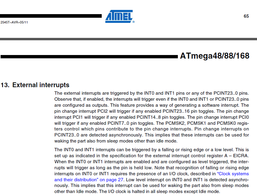
Textauszug aus einem Atmel ATmega48/88/168 Datenblatt
ATMEL 65 2545T-AVR-05/11 ATmega48/88/168 13. External interrupts The external interrupts are triggered by the INT0 and INT1 pins or any of the PCINT23..0 pins. Observe that, if enabled, the interrupts will trigger even if the INT0
in „ATmega Power-Down und Wakeup mit INT0“ · Mikrocontroller und Digitale Elektronik · · Screenshots
-
PDF
AVR_Uebersichtstabelle.pdf
44 PDIP 40 TQFP 44 ATmega8535 8 0.5 512 32 16 2.7-5.5 1 2 4 -- 1 1 Yes Yes 8 Yes Yes Yes Yes Yes 20 3 Yes PLCC 44 MLF 44 PDIP 40 TQFP 44 ATmega88 8 0.5 1024 23 20 1.8-5.5 1 2 6 Yes 1+USART 1 Yes Yes 8 Yes Yes Yes Yes Yes 26 26 Yes MLF 32 PDIP 28 TQFP 32 ATmega88 Automotive 8 0.512 1024 23 16 2.7-5.5 1 2 6 Yes 1+USART 1 Yes Yes 8 Yes Yes Yes Yes Yes 26 26 Yes MLF 32 TQFP 32 ATtiny11 1 -- -- 6 6 2.7-5.5 -- 1 -- -- -- -- -- -- -- Yes -- Yes Yes -- 4 1 -- PDIP
in „Unterschied der AVR'S“ · Mikrocontroller und Digitale Elektronik ·
-
PDF
Fusedoc_Schema.pdf
10K J E 1 2 C GND IC3 C V START R26 GND 1 9 RESET (ADC7)PA7 33 DTSM-3 1K GND + (ADC6)PA6 34 1 2 ATMEGA8-DOC (ADC5)PA5 35 DATA 12 XTAL2 (ADC4)PA4 36 1 PC6(/RESET) PC0(ADC0) 23 R7 1K RDY (ADC3)PA3 37 PC1(ADC1) 24 R8 1K BS1 XTAL1 13 XTAL1 (ADC2)PA2 38 D 22 25 XA0 SV2 MEGA8/88/168... 39 GND G 21 GND PC2
in „Fehlersuche defektes Bauteil (Fusebit Doctor)“ · Mikrocontroller und Digitale Elektronik ·
-
Datei
ttester_110k_20140511.diff
hfuse:w:0xc9:m +FUSES_CRY_L = -U lfuse:w:0x3f:m -U hfuse:w:0xd9:m +endif +endif + +ifeq ($(PARTNO),m88) +MCU = atmega88 +HEX_FLASH_FLAGS = --change-section-lma .eeprom=0x2000 +ifeq ($(OP_MHZ),1) +# RC operation ,CLK 1MHz +FUSES_INT = -U lfuse:w:0x62:m -U hfuse:w:0xdc:m +# -U efuse:w:0xf9:m +# Operation
-
PDF
nRF24L01plus.pdf
2.4GHz-HowTo von der Beschreibung abweichend sind die folgenden Verbindungen: • nRF24L01+ CE → Arduino D8 (ATMega8 PB0) • nRF24L01+ CSN → Arduino D4 (ATMega8 PD4) • nRF24L01+ IRQ → Arduino D3 (ATMega8 PD3) Gaaaanz wichtig der 100µF Kondensator nahe bei der 3,3V Versorgung für den nRF24L01+ nicht vergessen. Die
in „Repeating und Routing Netzwerk mit Arduino und nRF24L01+“ · Projekte & Code ·
-
PDF
AVRMicrocontrollers_Peripheral_Integration.pdf
ü ü ü ü 1 ü 1 6 (6) (6) (6) (6) (6) (6) ATmega48PB/88PB/168PB/328PB 32 4–32 0.5–2 1.8–5.5 20 10 8 ü ü ü 4 2/6 ü 2 1/3 ü ü ü ü 1/2 1/2 1/2 ü ü 6 ATmega80x/160x/320x/480x 28–48 8–48 1–6 1.8–5.5 20 10 16 ü ü ü 4 3 ü 5 ü ü ü ü ü ü 4 1 1 ü ü ü 3 ü ATmega64A/128A 64 64–128 4 2.7–5.5 16 10 8 ü ü ü 2 6 2 2 ü ü ü ü 2 1 1 ü 6 ATmega164PA/324PA/644PA/1284P 44 16–128 1–16 1.8–5.5 20 10 8 ü ü ü 4 2/2/4 ü 2 1/1/2 ü ü ü ü 2 1 1 ü 6 ü ATmega165PA/325PA/645P 44 16–64 1–4 1.8–5.5 16 10 8 ü ü 4 6 ü 2 3 ü ü ü ü 3 2 2 6 ü ATmega169PA/329PA
in „Nachfolger von Atmega169“ · Mikrocontroller und Digitale Elektronik ·
-
PDF
nRF24L01_.pdf
2.4GHz-HowTo von der Beschreibung abweichend sind die folgenden Verbindungen: • nRF24L01+ CE → Arduino D8 (ATMega8 PB0) • nRF24L01+ CSN → Arduino D4 (ATMega8 PD4) • nRF24L01+ IRQ → Arduino D3 (ATMega8 PD3) Gaaaanz wichtig der 100µF Kondensator nahe bei der 3,3V Versorgung für den nRF24L01+ nicht vergessen. Die
in „Repeating und Routing Netzwerk mit Arduino und nRF24L01+“ · Projekte & Code ·
-
PDF
top2008.pdf
ATTINY25, ATTINY26, ATTINY26L, ATTINY28L, ATTINY28V, ATTINY2313(DIP20), ATTINY2313V(DIP20),ATTINY2313, ATMEGA8, ATMEGA8L, ATMEGA16, ATMEGA16L, ATMEGA8535, ATMEGA8535L, ATMEGA8515, ATMEGA8515L, ATMEGA32, ATMEGA32L, ATMEGA48*PDIP28, ATMEGA88*PDIP28, ATMEGA88P*PDIP28, ATMEGA88PA*PDIP28,ATMEGA_ALL, ATMEGA168*PDIP28, ATMEGA328*PDIP28, ATMEGA328V*PDIP28, ATMEGA48V*PDIP28, ATMEGA88V*PDIP28, ATMEGA168V*PDIP28,ATMEGA_ALL, ATMEGA161, ATMEGA161L, ATMEGA162, ATMEGA162L, ATMEGA162V, ATMEGA162U, ATMEGA163, ATMEGA163L, AT90S2323
in „[V] Top 853 Universal Programmer + 74er Tester“ · Markt ·
-
Datei
uart.c
#define UART0_CONTROL UCSRB #define UART0_DATA UDR #define UART0_UDRIE UDRIE #elif defined(__AVR_ATmega48__) ||defined(__AVR_ATmega88__) ||\ defined(__AVR_ATmega168__) || defined(__AVR_ATmega48P__) ||\ defined(__AVR_ATmega88P__) || defined(__AVR_ATmega168P__) ||\ defined(__AVR_ATmega328P__) /* ATmega
in „[AVR-GCC] makefile SRC und #include“ · Mikrocontroller und Digitale Elektronik ·
-
Datei
CMakeLists.txt
flto -Wall -Wextra -Wmissing-prototypes -Wstrict-prototypes -c -std=gnu99) add_definitions(-mmcu=atmega88) list(APPEND MY_LINKER_FLAGS "-mmcu=atmega88 -flto") add_executable(foo foo.c) add_definitions(-O0) set_target_properties(foo PROPERTIES SUFFIX ".elf")
in „[AVR-GCC,CMake,Eclipse] interne gcc macros nicht im Indexer“ · Mikrocontroller und Digitale Elektronik ·
-
PDF
Compare_SCCB_ATmega_vs_STM32F429.pdf
Read Register 0x00 (ATmega328P <-> OV7670_with_FiFo) Read Register 0x00 (STM32F429 <-> OV7670_with_FiFo) Write Register 0x00, Value 0x88 (ATmega328P <-> OV7670_with_FiFo) Write Register 0x00, Value 0x88 (STM32F429 <-> OV7670
in „Brauche Unterstützung beim OV7670 (bzw. SCCB)“ · Mikrocontroller und Digitale Elektronik ·
-
Datei
uart.c
#define UART0_CONTROL UCSRB #define UART0_DATA UDR #define UART0_UDRIE UDRIE #elif defined(__AVR_ATmega48__) ||defined(__AVR_ATmega88__) || defined(__AVR_ATmega168__) || defined(__AVR_ATmega48P__) || defined(__AVR_ATmega88P__) || defined(__AVR_ATmega168P__) || defined(__AVR_ATmega328P__) /* ATmega with
in „ATmega1284p, UART Probleme“ · Mikrocontroller und Digitale Elektronik ·
-
Datei
uart.c
#define UART0_CONTROL UCSRB #define UART0_DATA UDR #define UART0_UDRIE UDRIE #elif defined(__AVR_ATmega48__) || defined(__AVR_ATmega88__) || defined(__AVR_ATmega168__) || defined(__AVR_ATmega48P__) || defined(__AVR_ATmega88P__) || defined(__AVR_ATmega168P__) || defined(__AVR_ATmega328P__) \ || defined(__AVR_ATmega3250__) || defined(__AVR_ATmega3290__) ||defined(__AVR_ATmega6450__) || defined(__AVR_ATmega6490__) /* ATmega with one USART */ #define ATMEGA_USART0 #define UART0_RECEIVE_INTERRUPT USART_RX_vect #define
in „UART Auswertung“ · Mikrocontroller und Digitale Elektronik ·
-
Datei
uart.c
#define UART0_CONTROL UCSRB #define UART0_DATA UDR #define UART0_UDRIE UDRIE #elif defined(__AVR_ATmega48__) || defined(__AVR_ATmega88__) || defined(__AVR_ATmega168__) || defined(__AVR_ATmega48P__) || defined(__AVR_ATmega88P__) || defined(__AVR_ATmega168P__) || defined(__AVR_ATmega328P__) \ || defined(__AVR_ATmega3250__) || defined(__AVR_ATmega3290__) ||defined(__AVR_ATmega6450__) || defined(__AVR_ATmega6490__) /* ATmega with one USART */ #define ATMEGA_USART0 #define UART0_RECEIVE_INTERRUPT USART_RX_vect #define
in „µC rechnet falsch oder ich finde den Fehler nicht“ · Mikrocontroller und Digitale Elektronik ·
-
Datei
uart.c
#define UART0_CONTROL UCSRB #define UART0_DATA UDR #define UART0_UDRIE UDRIE #elif defined(__AVR_ATmega48__) || defined(__AVR_ATmega88__) || defined(__AVR_ATmega168__) || defined(__AVR_ATmega48P__) || defined(__AVR_ATmega88P__) || defined(__AVR_ATmega168P__) || defined(__AVR_ATmega328P__) \ || defined(__AVR_ATmega3250__) || defined(__AVR_ATmega3290__) ||defined(__AVR_ATmega6450__) || defined(__AVR_ATmega6490__) /* ATmega with one USART */ #define ATMEGA_USART0 #define UART0_RECEIVE_INTERRUPT USART_RX_vect #define
in „µC rechnet falsch oder ich finde den Fehler nicht“ · Mikrocontroller und Digitale Elektronik ·
-
Datei
uart.c
#define UART0_CONTROL UCSRB #define UART0_DATA UDR #define UART0_UDRIE UDRIE #elif defined(__AVR_ATmega48__) || defined(__AVR_ATmega88__) || defined(__AVR_ATmega168__) || defined(__AVR_ATmega48P__) || defined(__AVR_ATmega88P__) || defined(__AVR_ATmega168P__) || defined(__AVR_ATmega328P__) \ || defined(__AVR_ATmega3250__) || defined(__AVR_ATmega3290__) ||defined(__AVR_ATmega6450__) || defined(__AVR_ATmega6490__) /* ATmega with one USART */ #define ATMEGA_USART0 #define UART0_RECEIVE_INTERRUPT USART_RX_vect #define
in „avr dude Programm zu groß? Eclipse GCC“ · Mikrocontroller und Digitale Elektronik ·
-
Datei
uart.c
#define UART0_CONTROL UCSRB #define UART0_DATA UDR #define UART0_UDRIE UDRIE #elif defined(__AVR_ATmega48__) ||defined(__AVR_ATmega88__) || defined(__AVR_ATmega168__) || defined(__AVR_ATmega48P__) || defined(__AVR_ATmega88P__) || defined(__AVR_ATmega168P__) || defined(__AVR_ATmega328P__) /* ATmega with
in „ATMega nach ADC BascomPRG stk500 WEG!“ · Mikrocontroller und Digitale Elektronik ·
-
Datei
uart.c
#define UART0_CONTROL UCSRB #define UART0_DATA UDR #define UART0_UDRIE UDRIE #elif defined(__AVR_ATmega48__) ||defined(__AVR_ATmega88__) || defined(__AVR_ATmega168__) || defined(__AVR_ATmega48P__) || defined(__AVR_ATmega88P__) || defined(__AVR_ATmega168P__) || defined(__AVR_ATmega328P__) /* ATmega with
in „ATmega168 Bootloader“ · Mikrocontroller und Digitale Elektronik ·
-
Datei
uart.c
#define UART0_CONTROL UCSRB #define UART0_DATA UDR #define UART0_UDRIE UDRIE #elif defined(__AVR_ATmega48__) ||defined(__AVR_ATmega88__) || defined(__AVR_ATmega168__) || defined(__AVR_ATmega48P__) || defined(__AVR_ATmega88P__) || defined(__AVR_ATmega168P__) || defined(__AVR_ATmega328P__) /* ATmega with
in „fleurys I2C + UART lib halten in Kombination die Hauptschleife an!“ · Mikrocontroller und Digitale Elektronik ·
-
Datei
uart.c
#define UART0_CONTROL UCSRB #define UART0_DATA UDR #define UART0_UDRIE UDRIE #elif defined(__AVR_ATmega48__) ||defined(__AVR_ATmega88__) || defined(__AVR_ATmega168__) || defined(__AVR_ATmega48P__) || defined(__AVR_ATmega88P__) || defined(__AVR_ATmega168P__) || defined(__AVR_ATmega328P__) /* ATmega with
in „Inkonsistentes Verhalten einfachem avr-gcc-codes“ · Mikrocontroller und Digitale Elektronik ·
-
Datei
uart.c
#define UART0_CONTROL UCSRB #define UART0_DATA UDR #define UART0_UDRIE UDRIE #elif defined(__AVR_ATmega48__) ||defined(__AVR_ATmega88__) || defined(__AVR_ATmega168__) || defined(__AVR_ATmega48P__) || defined(__AVR_ATmega88P__) || defined(__AVR_ATmega168P__) || defined(__AVR_ATmega328P__) /* ATmega with
in „RFM70 Timing Problem?“ · Mikrocontroller und Digitale Elektronik ·
-
Datei
uart.c
#define UART0_CONTROL UCSRB #define UART0_DATA UDR #define UART0_UDRIE UDRIE #elif defined(__AVR_ATmega48__) ||defined(__AVR_ATmega88__) || defined(__AVR_ATmega168__) || defined(__AVR_ATmega48P__) || defined(__AVR_ATmega88P__) || defined(__AVR_ATmega168P__) || defined(__AVR_ATmega328P__) /* ATmega with
in „Float via UART an PC senden“ · Mikrocontroller und Digitale Elektronik ·
-
Datei
uart.c
#define UART0_CONTROL UCSRB #define UART0_DATA UDR #define UART0_UDRIE UDRIE #elif defined(__AVR_ATmega48__) ||defined(__AVR_ATmega88__) || defined(__AVR_ATmega168__) || defined(__AVR_ATmega48P__) || defined(__AVR_ATmega88P__) || defined(__AVR_ATmega168P__) || defined(__AVR_ATmega328P__) /* ATmega with
in „UART bei externer Stromquelle“ · Mikrocontroller und Digitale Elektronik ·
-
PDF
AVR341.pdf
change is triggered. 3.5 Connecting the touch screen to the AVR The implementation example uses the ATmega88 as touch screen controller (see datasheet ATmega88 for details). Figure 3-1 and Figure 3-2 illustrates how to connect the ATmega88 to respectively a 5-wire and a 4-wire touch screen. In order to
in „Anleitung eines Touch Lcd“ · Mikrocontroller und Digitale Elektronik ·
-
 Bild
Bild
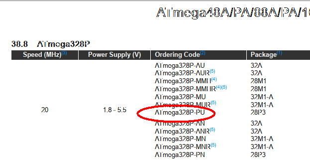
Tabellenausschnitt mit ATmega328P Bestellcodes
ATmega48A/PA/88A/PA/16... 38.8 ATmega328P Speed (MHz) Power Supply (V) Ordering Code Package ATmega328P-AU 32A ATmega328P-AUR 32A ATmega328P-MMI 2.8M1 ATmega328P-MMIR 2.8M1 ATmega328P-MU 32M1-A ATmega328P-MUIR 32M1-A ATmega328P-PU 28IP3 ATmega328P-AN 32A ATmega328P-ANIR 32A ATmega328P-MN 32M1-A ATmega328P-MNIR 32M1-A ATmega328P-PN 28IP3
in „ATmega: unerwatetes Reset“ · Mikrocontroller und Digitale Elektronik · · Screenshots
-
PDF
TT_Bausatz_mit_Deek_Robot-DIL28_Umbauten.pdf
TransistorTester.elf > TransistorTester.lss 16 MHz operation configured. AVR Memory Usage ---------------- Device: atmega328p Program: 32224 bytes (98.3% Full) (.text + .data + .bootloader) Data: 202 bytes (9.9% Full) (.data + .bss + .noinit) EEPROM: 906 bytes (88.5% Full) (.eeprom) > Process Exit Code: 0 > Time Taken
-
PDF
techb_myavr_board_20.pdf
Beschreibung myAVR myAVR Board 2.0 USB • Lern- und Experimentierboard für ATMEL Mikrocontroller (ATmega8/48/88/168) • Mit Controller und typischen Ein- und Ausgabegeräten (Taster, LEDs, usw.) • Material: FR4, 1,5 mm; 0.35 µm Cu • Leiterplatte gebohrt, verzinnt, Industriefertigung, robust, bedruckt •
in „Probleme mit rjmp beim AVR Atmega 8L“ · Mikrocontroller und Digitale Elektronik ·