-
PDF
SermultiChip.pdf
Multimeter Display Controller …. Atmega48 Display Software 7905 232 DCDC Conv. 5->9 Optische Trennung 232 Attiny45 USB Stack USB Buchse Mini Messgerät Nr2… Messgerät Nr3… USB Hub PC mit Auswertesoftware USB to 232 driver Konfiguration 2 (LOW COST) auch für mikrocontrolleranwendungen (Empfangseitig) Multimeter
in „Multimeter mit serieller Schnittstelle für unter 10€“ · Projekte & Code ·
-
PDF
avr-libc-user-manual-1.8.0.pdf
Doxygen 1.3 Supported Devices 5 • attiny26 • attiny261 • attiny261a • attiny28 [1] • attiny2313 • attiny2313a • attiny40 • attiny4313 • attiny43u • attiny44 • attiny44a • attiny45 • attiny461 • attiny461a • attiny48 • attiny84 • attiny84a
in „Interrupt Probleme beim Arduino“ · Mikrocontroller und Digitale Elektronik ·
-
PDF
ir-detect.pdf
IR-Bewegungsmelder für Luxeon-LEDs Mit einem kleinen IR-Bewegungsmelder von Panasonic und einem ATTiny25 ist diese kleine Platine ausgestattet, welche durch Infrarotstrahlungen Bewegungen erkennt und eine Luxeon- LED ansteuert. Praktische Anwendungen wären Gehwege oder wie bei mir der Treppenaufgang
in „Atmega8 an zwei Knopfzellen betreiben (6V)“ · Mikrocontroller und Digitale Elektronik ·
-
PDF
pbwake.pdf
3W C2 100n GND 8 C C 2 5 V Q1 PB0 1 6 PB1 IRF530 7 PB2 3 2 U1 R2 PB3 10k 3 PB4 Microcontroller 1 ATTiny-13 RESET/PB5 ATTiny-25 ATTiny-45 C N ATTiny-85 C R 0 G (ATMega-328P different pinout) 1 4 GND GND J3 1 V DEBUG + GND Michael Buesch <m@bues.ch> Sheet: / D File: pbwake.sch D Title: pbwake Size: A4
in „Powerbank-Wecker für neue ANKER Powerbank“ · Analoge Elektronik und Schaltungstechnik ·
-
PDF
Arduino.pdf
AVR_ATmega2560__) ADMUX = _BV(REFS0) | _BV(MUX4) | _BV(MUX3) | _BV(MUX2) | _BV(MUX1); #elif defined (__AVR_ATtiny24__) || defined(__AVR_ATtiny44__) || defined(__AVR_ATtiny84__) ADMUX = _BV(MUX5) | _BV(MUX0); #elif defined (__AVR_ATtiny25__) || defined(__AVR_ATtiny45__) || defined(__AVR_ATtiny85__) ADMUX = _BV(
in „Aref Spannung, was ist besser?“ · Mikrocontroller und Digitale Elektronik ·
-
Datei
usiTwiSlave.c
USI_START_VECTOR USI_START_vect #define USI_OVERFLOW_VECTOR USI_OVERFLOW_vect #elif defined( __AVR_ATtiny24A__ ) | \ defined( __AVR_ATtiny44A__ ) | \ defined( __AVR_ATtiny24__ ) | \ defined( __AVR_ATtiny44__ ) | \ defined( __AVR_ATtiny84__ ) #define DDR_USI DDRA #define PORT_USI PORTA #define PIN_USI PINA
in „I2C Übertragungsproblem“ · Mikrocontroller und Digitale Elektronik ·
-
Datei
usiTwiSlave.c
USI_START_VECTOR USI_START_vect #define USI_OVERFLOW_VECTOR USI_OVERFLOW_vect #elif defined( __AVR_ATtiny24A__ ) | \ defined( __AVR_ATtiny44A__ ) | \ defined( __AVR_ATtiny24__ ) | \ defined( __AVR_ATtiny44__ ) | \ defined( __AVR_ATtiny84__ ) #define DDR_USI DDRA #define PORT_USI PORTA #define PIN_USI PINA
in „Abfrage Taster durch USI vom Slave mit zwei AVR“ · Mikrocontroller und Digitale Elektronik ·
-
Datei
usiTwiSlave.c
USI_START_VECTOR USI_START_vect #define USI_OVERFLOW_VECTOR USI_OVERFLOW_vect #elif defined( __AVR_ATtiny24A__ ) | \ defined( __AVR_ATtiny44A__ ) | \ defined( __AVR_ATtiny24__ ) | \ defined( __AVR_ATtiny44__ ) | \ defined( __AVR_ATtiny84__ ) #define DDR_USI DDRA #define PORT_USI PORTA #define PIN_USI PINA
in „Attiny - Arduino I2C Problem“ · Mikrocontroller und Digitale Elektronik ·
-
Datei
mega8.txt
R16 brne W_100us_2 pop R16 dec R16 brne W_100us_3 pop R16 ret ByteTransf: sbic PINC,3 ; Antwort v. ATTiny durch low-Signal auf PIN C3 rjmp ByteTransf ; ATTiny noch nicht bereit rcall SPI_senden ; Byte senden fertig: sbis PORTC,3 ; Antwort v. ATTiny durch high-Signal auf PIN C3 rjmp fertig ; ATTiny noch
in „SPI Kopplung von ATmega8 und ATtiny 2313“ · Projekte & Code ·
-
PDF
AVR_ATtiny_24_44_84.pdf
is shared by all the other 16- bit registers. See “Accessing 16-bit Registers” on page 105. 112 ATtiny24/44/84 8006K–AVR–10/10 ATtiny24/44/84 12.11.7 ICR1H and ICR1L – Input Capture Register 1 Bit 7 6 5 4 3 2 1 0 0x25 (0x45) ICR1[15:8] ICR1H 0x24 (0x44) ICR1[7:0] ICR1L Read/Write R/W R/W R/W R/W R/W
in „AVR Programm brennen ohne Bootloader“ · Mikrocontroller und Digitale Elektronik ·
-
Datei
Netzmessung_TWI.cpp
(inPinV); //using the voltage waveform if ((startV < (ADC_COUNTS*0.55)) && (startV > (ADC_COUNTS*0.45))) st=true; //check its within range if ((millis()-start)>timeout) st = true; } //---------------------------------------------------------------------------------------------------------------------
in „AVR Frequenzmessung, DS18S20“ · Mikrocontroller und Digitale Elektronik ·
-
PDF
Atiny2313.pdf
the operation of counting external events. The timing diagram for the CTC mode is shown in Figure 45 on page 99. The counter value (TCNT1) increases until a compare match occurs with either OCR1A or ICR1, and then counter (TCNT1) is cleared. 98 ATtiny2313/V 2543I–AVR–04/06 ATtiny2313/V Figure 45. CTC
in „Suche tutorial“ · Mikrocontroller und Digitale Elektronik ·
-
Datei
main.c
printbyte(data >> 8); printbyte(data); } #endif static void timer1_init (void) { #if defined (__AVR_ATtiny45__) || defined (__AVR_ATtiny85__) // ATtiny45 / ATtiny85: #if F_CPU >= 16000000L OCR1C = (F_CPU / F_INTERRUPTS / 8) - 1; // compare value: 1/15000 of CPU frequency, presc = 8 TCCR1 = (1 << CTC1) |
in „IRMP-Anwendung“ · Mikrocontroller und Digitale Elektronik ·
-
Datei
Digitalanzeige.ino
const byte input_pin = 3; // Pin 2 am ATtiny45 (PB3) const byte output_pin = 4; // Pin 7 am ATtiny45 (PB2) bool last_state = HIGH; unsigned long last_trigger_time = 0; const unsigned long min_interval = 50; // Mikrosekunden // Für Impulssteuerung
in „Impulsverdoppler für alte Heidenhain Anzeige“ · Projekte & Code ·
-
PDF
attiny84.pdf
is shared by all the other 16- bit registers. See “Accessing 16-bit Registers” on page 105. 112 ATtiny24/44/84 8006H–AVR–10/09 ATtiny24/44/84 12.11.7 ICR1H and ICR1L – Input Capture Register 1 Bit 7 6 5 4 3 2 1 0 0x25 (0x45) ICR1[15:8] ICR1H 0x24 (0x44) ICR1[7:0] ICR1L Read/Write R/W R/W R/W R/W R/W
in „Attiny 84 ISP?!“ · Mikrocontroller und Digitale Elektronik ·
-
Datei
USI_TWI_Slave.h
Supported devices : All device with USI module can be used. * The example is written for the ATmega169, ATtiny26 & ATtiny2313 * * AppNote : AVR312 - Using the USI module as a TWI slave * * Description : Header file for USI_TWI driver * * * ********************************************************************
in „AVR: I2C bleibt hängen“ · Mikrocontroller und Digitale Elektronik ·
-
PDF
doc2535.pdf
5 5.5 V CC(V) Figure 19-39. I/O Pin Input Hysteresis vs. V CC I/O PIN INPUT HYSTERESIS vs. V CC 0.45 0.4 -40 ºC 0.35 ) ( 0.3 i 25 ºC e 0.25 e s H 0.2 u 85 ºC p 0.15 I 0.1 0.05 0 1.5 2 2.5 3 3.5 4 4.5 5 5.5 V CC(V) 142 ATtiny13 2535J–AVR–08/10 ATtiny13 Figure 19-40. Reset Pin as I/O - Input Threshold
in „RGB PWM mit Attiny13“ · Mikrocontroller und Digitale Elektronik ·
-
PDF
doc2535.pdf
5 5.5 V CC(V) Figure 19-39. I/O Pin Input Hysteresis vs. V CC I/O PIN INPUT HYSTERESIS vs. V CC 0.45 0.4 -40 ºC 0.35 ) ( 0.3 i 25 ºC e 0.25 e s H 0.2 u 85 ºC p 0.15 I 0.1 0.05 0 1.5 2 2.5 3 3.5 4 4.5 5 5.5 V CC(V) 142 ATtiny13 2535J–AVR–08/10 ATtiny13 Figure 19-40. Reset Pin as I/O - Input Threshold
in „ATtiny13 mit 20MHz“ · Mikrocontroller und Digitale Elektronik ·
-
PDF
DD19FCD3d01.pdf
5 5.5 V CC(V) Figure 19-39. I/O Pin Input Hysteresis vs. V CC I/O PIN INPUT HYSTERESIS vs. V CC 0.45 0.4 -40 ºC 0.35 ) ( 0.3 i 25 ºC e 0.25 e s H 0.2 u 85 ºC p 0.15 I 0.1 0.05 0 1.5 2 2.5 3 3.5 4 4.5 5 5.5 V CC(V) 142 ATtiny13 2535I–AVR–05/08 ATtiny13 Figure 19-40. Reset Pin as I/O - Input Threshold
in „HV-Prog für ATtiny13“ · Mikrocontroller und Digitale Elektronik ·
-
Datei
chips.xml
<CHIPLIST> <CHIP> <NAME>ATtiny13A</NAME> <FLASH>1024</FLASH> <EEPROM>64</EEPROM> <SIG>0x0007901E</SIG> <PAGE>16</PAGE> <LFUSE layout="4">YES</LFUSE> <HFUSE layout="6">YES</HFUSE> <EFUSE>NO</EFUSE> <LOCK>YES</LOCK> <CALIB>YES</CALIB
in „extreme Burner AVR 1.4.3 + ATTiny Erweiterungen“ · Mikrocontroller und Digitale Elektronik ·
-
 Bild
Bild
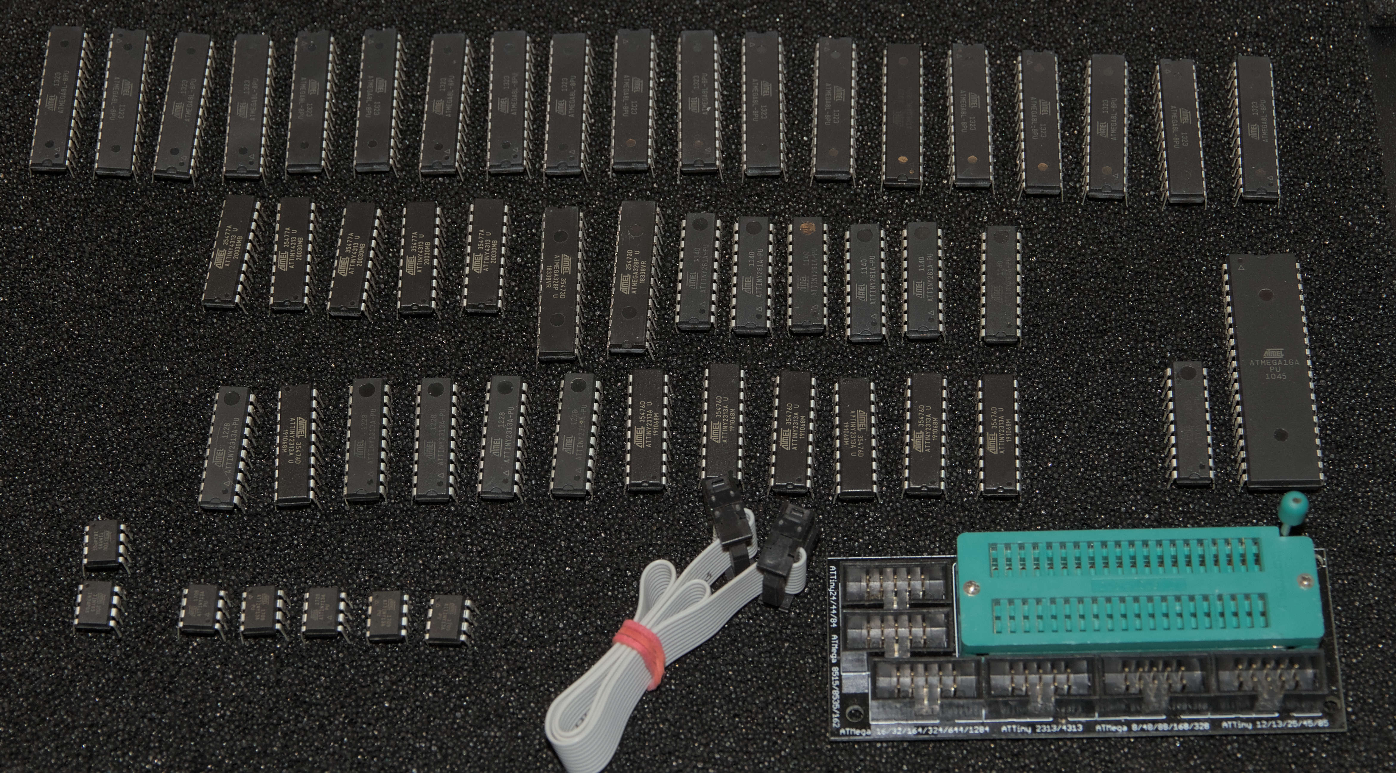
Verschiedene Mikrocontroller und ICs auf dunklem Untergrund
ATmega328P, ATmega168, ATmega8, ATmega4, ATmega16, ATmega32, ATmega64, ATmega128, ATmega2560, ATtiny2313, ATtiny45, ATtiny85
in „[V] Set: STK 500, Dragon, diverse ATtiny und -mega, passendes Buch, Zubehör“ · Markt · · Fotos
-
Datei
tiny_printf.c
aufgerufen /* -------------------------------------------------- Registernamen fuer ATMega8 und ATtiny2313 -------------------------------------------------- */ #if defined (__AVR_ATmega8__) || defined (__AVR_ATtiny2313__) #define UBRR0 UBRR #define UBRR0L UBRRL #define UBRR0H UBRRH #define UCSR0A UCSRA
in „"Berechnungsfunktion" liefert immer 0“ · Mikrocontroller und Digitale Elektronik ·
-
PDF
PCBA_with_elecrow_quotation_BOM.pdf
R-EU_R0805 R0805 R1 RESISTOR, 0,000 0,000 2 Free 1 33 R-EU_R0805 R0805 R3 RESISTOR, 0,000 0,000 2 Free 1 ATTINY45-20PU ATTINY45-20PU DIP254P762X533-8 U1 8-bit 1,450 1,450 8 Y 1 BC847C-7-F BC847C-7-F SOT103P240X110-3N U3 NPN 0,100 0,100 3 Y 9,050 31 8
in „Erfahrungen mit Platinen von www.elecrow.com“ · Platinen ·
-
PDF
ATtiny26.pdf
5.5 VCC(V) Figure 117. Reset Input Pin Hysteresis vs. V CC RESET INPUT PIN HYSTERESIS vs. V CC 0.5 0.45 -40°C 0.4 0.35 V ( 0.3 o s0.25 r 25°C T 0.2 0.15 0.1 85°C 0.05 0 2 2.5 3 3.5 4 4.5 5 5.5 VCC (V) 154 ATtiny26(L) 1477K–AVR–08/10 ATtiny26(L) BOD Thresholds and Figure 118. BOD Thresholds vs. Temperature
in „ATtiny26(L) Analog-Digital-Wandler ( ADC ) Datenblattübersetzung“ · Mikrocontroller und Digitale Elektronik ·
-
PDF
tiny13.pdf
Fuse bits before programming the LB1 and LB2. 2. “1” means unprogrammed, “0” means programmed 102 ATtiny13 2535E–AVR–10/04 ATtiny13 Fuse Bytes The ATtiny13 has two Fuse bytes. Table 44 and Table 45 describe briefly the functional- ity of all the fuses and how they are mapped into the Fuse bytes. Note
in „ATtiny13 Datenblatt External Clock Source on T0-Pin“ · Mikrocontroller und Digitale Elektronik ·
-
PDF
tiny13_doc2535.pdf
LB1 and LB2. 2. “1” means unprogrammed, “0” means programmed 103 2535H–AVR–10/07 Fuse Bytes The ATtiny13 has two Fuse bytes. Table 44 and Table 45 describe briefly the functional- ity of all the fuses and how they are mapped into the Fuse bytes. Note that the fuses are read as logical zero, “0”, if
in „Atmel AVRs: SRAM so unwichtig?“ · Mikrocontroller und Digitale Elektronik ·
-
PDF
avrdude.pdf
m8535 ATmega8535 m88 ATmega88 m88p ATmega88P m8u2 ATmega8U2 Chapter 2: Command Line Options 6 t10 ATtiny10 t11 ATtiny11 t12 ATtiny12 t13 ATtiny13 t15 ATtiny15 t2313 ATtiny2313 t24 ATtiny24 t25 ATtiny25 t26 ATtiny26 t261 ATtiny261 t4 ATtiny4 t4313 ATtiny4313 t44 ATtiny44 t45 ATtiny45 t461 ATtiny461 t5
in „AVRDude als Tool in AVR Studio 4 einbinden“ · Mikrocontroller und Digitale Elektronik ·
-
Datei
main.c
diff = max_v - *b; *b = *b + (diff * (0.01 * s)); } int main(void) { uint8_t mask; #ifdef __AVR_ATtiny10__ CCP=0xD8; // configuration change protection, write signature CLKPSR=1; // set cpu clock prescaler =1 (8Mhz) (attiny 4/5/9/10) mask=_BV(PB0); #else CLKPR=_BV(CLKPCE); CLKPR=0; // set clock prescaler to 1 (attiny 25/45/85/24/44/84/13/13A) mask=_BV(PB0); #endif DDRB|=mask; while(1) { unsigned int winkel; unsigned char r, g, b; for (winkel=0; winkel < 256; winkel++) { hsv_to_rgb(winkel, 100, 100, &r, &g, &b);
in „Lightweight WS2811/WS2812 Library“ · Mikrocontroller und Digitale Elektronik ·
-
Datei
1wire.cpp
along with this program. If not, see <http://www.gnu.org/licenses/>. // // //VERSION 1.1 DS2423 for ATTINY2313 and ATTINY25 //FOR MAKE by hand /* avr-gcc -mmcu=[attiny25|attiny2313] -O2 -c ow_slave_DS2423.c avr-gcc.exe -mmcu=[attiny25|attiny2313] ow_slave_DS2423.o -o ow_slave_DS2423.elf avr-objcopy -O ihex
in „1-Wire Slave auf AVR“ · Mikrocontroller und Digitale Elektronik ·
-
PDF
ATTiny15L.pdf
Vcc 5V 120 TA= 25C 100 TA= 85˚C 80 A ( O I 60 40 20 0 0 0.5 1 1.5 2 2.5 3 3.5 4 4.5 5 VOP(V) 70 ATtiny15L 1187G–AVR–06/07 ATtiny15L Figure 45. Pull-up Resistor Current vs. Input Voltage PULL-UP RESISTOR CURRENT vs. INPUT VOLTAGE Vcc 2.7V 30 T = 25C A 25 T = 85C A 20 A ( 15 O I 10 5 0 0 0.5 1 1.5 2 2.5
in „ATtiny 15 Datenblatt nicht auffindbar??“ · Mikrocontroller und Digitale Elektronik ·
-
PDF
Tools_-_Abzugeben.pdf
vorsätzlicher Verletzungen meiner Pflichten als Verkäufer bleibt davon unberührt Jtag ICE Mk2 mit Stecker 45€ Atmel-ICE PCBA Kit + Adapter 25€ ATSMARTCARD-XPRO 10€ AT88CKECC-AWS-XSTK 25€ ATCRYPTOAUTH-XPRO 5€ ATQT1-XPRO 5€ ATPROTO1-XPRO 5€ ATSAMR21ZLL-EK 30€ ATSAMR21-XPRO 10€ ATSAMD11-XPRO 5€ ATTINY817-XPRO 5€ ATTiny817-Xplained 2€ ATTiny817-QTMOISTD 20€ ATXPRO-10PIN 2€ ATAVRSBPR1 3€ ATAVRSBIN1 3€ ATBNO055-XPRO 5€ OLED1 Xplained Pro 3€ USB Levelshifter 5€ AT90USBKEY 25€ ATSAMW25 Xplained 5€ SAMA5D3 Xplained 25€
in „[V] Tools Atmel Microchip Chipcon/TI - Hobbyaufgabe“ · Markt ·
-
PDF
ATtiny.pdf
(ATtiny12V-1) – 0 - 2 MHz (ATtiny11L-2) – 0 - 4 MHz (ATtiny12L-4) – 0 - 6 MHz (ATtiny11-6) – 0 - 8 MHz (ATtiny12-8) Pin Configuration ATtiny10/11 ATtiny12 PDIP/SOIC PDIP/SOIC (RESET) PB5 1 8 VCC (RESET) PB5
in „Tiny 11 ,was ist davon zu halten?“ · PC Hard- und Software ·
-
Datei
V1.5_Master_6.12..txt
zu sendende Byte ist in R18 abgelegt out PORTC,R10 ; Slave select Bt2: sbic PINC,3 ; Antwort v. ATTiny durch low-Signal auf PIN C3 rjmp Bt2 ; ATTiny noch nicht bereit rcall SPI_senden ; Byte senden (R18) out PORTC,R11 ; Slave deselektieren Bt3: sbis PINC,3 ; Antwort v. ATTiny durch high-Signal auf PIN
in „SPI Kopplung von ATmega8 und ATtiny 2313“ · Projekte & Code ·
-
Datei
fuselayout.xml
Enable Serial Program and Data Downloading" default="0" /> </LAYOUT> <LAYOUT id="5" comment="For ATTiny25/45/85"> <BIT position="0" name="CKSEL0" details="Select Clock source" default="0" /> <BIT position="1" name="CKSEL1" details="Select Clock source" default="1" /> <BIT position="2" name="CKSEL2" details
in „extreme Burner AVR 1.4.3 + ATTiny Erweiterungen“ · Mikrocontroller und Digitale Elektronik ·
-
Datei
Pin.h
AVR_ATmega168P__) | defined(__AVR_ATmega168__) | \ defined(__AVR_ATmega32U4__) | \ defined(__AVR_ATtiny85__) | defined(__AVR_ATtiny45__) | defined(__AVR_ATtiny25__) #define FAST_TOGGLE #endif #define PARAMETERLIST \ volatile __attribute__((unused)) uint8_t * DDR , \ volatile __attribute__((unused)) uint8
in „Brauche Hilfe AT Mega 8 im Raum Bremen evlt. vor Ort“ · Mikrocontroller und Digitale Elektronik ·
-
Datei
fuse.c
programmable attinys * . reset hi-low fuses to factory default on target devices * . layout to drop-on attiny13, attiny25/45/85 8 pin devices targets * . attiny24/44/84 targets needs additional breadboard and jumper wires * . standalone operations, fuses show on 7 segment display * * . project fuse setting
in „Attiny85 neu verfust?“ · Mikrocontroller und Digitale Elektronik ·
-
Datei
Arduino.h
LSBFIRST 0 #define MSBFIRST 1 #define CHANGE 1 #define FALLING 2 #define RISING 3 #if defined(__AVR_ATtiny24__) || defined(__AVR_ATtiny44__) || defined(__AVR_ATtiny84__) #define DEFAULT 0 #define EXTERNAL 1 #define INTERNAL1V1 2 #define INTERNAL INTERNAL1V1 #elif defined(__AVR_ATtiny25__) || defined(__AVR_ATtiny45__) || defined(__AVR_ATtiny85__) #define DEFAULT 0 #define EXTERNAL 4 #define INTERNAL1V1 8 #define INTERNAL INTERNAL1V1 #define INTERNAL2V56 9 #define INTERNAL2V56_EXTCAP 13 #else #if defined(__AVR_ATmega1280__) || defined(_
in „Sekunden,Minuten zählen mit der Funktion Millis()“ · Mikrocontroller und Digitale Elektronik ·
-
Datei
Bootloader.bas
Version '****** MCU Einstellungen ******************************* $crystal = 8000000 '$regfile = "attiny45.dat" 'AVR Controller 'Const Avr_setting = "tiny45" $regfile = "m328pdef.dat" Const Avr_setting = "mega328p" 'Benutzerdefinierter AVR: '$regfile = "attiny45.dat" 'Const Avr_setting = "user" 'Const
in „Probleme mit Bootloader bei ATmega328p“ · Mikrocontroller und Digitale Elektronik ·
-
Datei
wuerfel_t45.bas
' Würfel mit ATtiny45 ' 1 2 ' 3 4 5 ' 6 7 ' Belegung ' Portb.3 Led 4 ' Portb.2 Led 1 und 7 ' Portb.1 Led 6 und 2 ' Portb.0 Led 3 und 5 ' Leds in Reihe geschaltet um Strom zu sparen ' Portb.4 Piezospeaker für Knattergeräusch ' Portb.5 Taster zum Start des Würfels $regfile = "attiny45.dat" $crystal = 1000000 ' used internal crystal $hwstack = 32 ' default use 32 $swstack = 10 ' default use 10 $framesize = 40 ' default use 40 Taster Alias Pinb.5 Ledport Alias Portb Speaker Alias
in „Schüttelwürfel“ · Mikrocontroller und Digitale Elektronik ·
-
Datei
Funzt_nicht.txt
0x52 = (unknown) Device code: 0x53 = (unknown) Device code: 0x54 = (unknown) Device code: 0x55 = ATtiny12 Device code: 0x56 = ATtiny15 Device code: 0x57 = (unknown) Device code: 0x58 = (unknown) Device code: 0x59 = (unknown) Device code: 0x5a = (unknown) Device code: 0x5b = (unknown) Device code: 0x5c = ATtiny28 Device code: 0x5d = (unknown) Device code: 0x5e = ATtiny4313 Device code: 0x5f = (unknown) Device code: 0x60 = ATmega161 Device code: 0x61 = (unknown) Device code: 0x62 = (unknown) Device code: 0x63
in „Probleme mit AVRDUDESS 2.13“ · Mikrocontroller und Digitale Elektronik ·
-
Datei
avr_sim_deviceu.pas
ADC3', {2} 'ATtiny11'+ { 1 } '*PB5 RESET'+ { 2 } '*PB3 XTAL1'+ { 3 } '*PB4 XTAL2'+ { 4 } '*GND'+ { 5 } '*PB0 AIN0'+ { 6 } '*PB1 INT0 AIN1'+ { 7 } '*PB2 T0'+ { 8 } '*VCC', {3} 'ATtiny12'+ { 1 } '*PB5 RESET'+ { 2 } '*PB3
-
PDF
sammelbestellung.pdf
Supply Bus 2 Versand sofort Transceiver RoHS: RoHS-konform 0,531 € 2,66 € Mouser-Nr.: 595-SN74LVC2T45DCUR 5 Verpackungswahl: Herst.- Nr.: SN74LVC2T45DCUR Cut-Tape Hersteller: Texas Instruments Verfügbarkeit Beschr.: Übersetzungsspannungs-Pegel Dual-Bit Dual Supply 5 Versand sofort Transceiver RoHS: RoHS-konform
-
Datei
main.c
/* Name: main.c * Project: Data input based on AVR USB driver with TINY45 * V3: 2 inputs ADC2/PB4 ADC3/PB3, pas de switch, led sur PB1 (on=0) * Author: Jacques Lepot * Creation Date: 2008-04-19 * Copyright: (c) 2008 by Jacques LEpot * License: Proprietary, free under certain
in „Problem mit libUSB - wie Gerät ansprechen?“ · Softwareentwicklung ·
-
Datei
Bootloader.bas
Version '****** MCU Einstellungen ******************************* $crystal = 8000000 '$regfile = "attiny45.dat" 'AVR Controller 'Const Avr_setting = "tiny45" $regfile = "m328pdef.dat" Const Avr_setting = "mega328p" 'Benutzerdefinierter AVR: '$regfile = "attiny45.dat" 'Const Avr_setting = "user" 'Const
in „Probleme mit Bootloader bei ATmega328p“ · Mikrocontroller und Digitale Elektronik ·
-
Datei
Bootloader.bas
Version '****** MCU Einstellungen ******************************* $crystal = 8000000 '$regfile = "attiny45.dat" 'AVR Controller 'Const Avr_setting = "tiny45" $regfile = "m328pdef.dat" Const Avr_setting = "mega328p" 'Benutzerdefinierter AVR: '$regfile = "attiny45.dat" 'Const Avr_setting = "user" 'Const
in „Probleme mit Bootloader bei ATmega328p“ · Mikrocontroller und Digitale Elektronik ·
-
Datei
telefonadapter.c
/* Programm für ATtiny25 * h#s Henrik Haftmann, TU Chemnitz, 31. März 2009 - 8. Oktober 2015 * tabsize = 8, encoding = utf-8 (ohne Windows-Header BOM) */ #include <avr/io.h> #include <avr/pgmspace.h> #include <avr/interrupt.h
in „HEX-File passt nicht in Attiny 25“ · Mikrocontroller und Digitale Elektronik ·
-
Datei
SolderingStation.asm
with tabs set to 8 .NOLIST ; Disable listfile generation ; please uncomment for the desired MC ; ATTiny 25 ;.include "tn25def.inc" ; ATTiny 45 ;.include "tn45def.inc" ; ATtiny 85 .include "tn85def.inc" .LIST ; ; constants 1 Mhz clk (8 mhz /8) , PB 0-1 outputs ,PB 2-4 input ; ; today : a soldering iron
in „Erfahrungen mit DIY-Lötstationen“ · Mikrocontroller und Digitale Elektronik ·
-
Datei
i2c-slave.c
****************************************************************************/ #if defined(__AVR_ATtiny2313__) #define USI_DDR DDRB #define USI_PORT PORTB #define USI_PIN PINB #define USI_SDA PB5 #define USI_SCL PB7 #elif defined(__AVR_ATtiny25__) | defined(__AVR_ATtiny45__) | defined(__AVR_ATtiny85_
in „LCD ueber i2c mit ATMega88PA“ · Mikrocontroller und Digitale Elektronik ·
-
Datei
rainbow.c
------------------------------------------------------------------- */ #ifdef TIM1_COMPA_vect // ATtiny84 ISR(TIM1_COMPA_vect) #else ISR(TIMER1_COMPA_vect) #endif { PORTB ^= (1 <<PB1); (void) irmp_ISR(); // call irmp ISR } ISR(TIMER2_COMP_vect) //10ms Tick fuer Delays / Aufrufe { static uint16_t i10ms_Count
in „Lightweight WS2811/WS2812 Library“ · Mikrocontroller und Digitale Elektronik ·
-
PDF
Attiny24a-44a-84a.pdf
is shared by all the other 16- bit registers. See “Accessing 16-bit Registers” on page 103. 110 ATtiny24A/44A/84A 8183F–AVR–06/12 ATtiny24A/44A/84A 12.11.7 ICR1H and ICR1L – Input Capture Register 1 Bit 7 6 5 4 3 2 1 0 0x25 (0x45) ICR1[15:8] ICR1H 0x24 (0x44) ICR1[7:0] ICR1L Read/Write R/W R/W R/W R
in „Kann jemand über meine Inialisierung drüberfliegen?“ · Mikrocontroller und Digitale Elektronik ·