-
Datei
AVRxt.asm
; SLdt 2405061640 PIT-Interrupt auf AVR64EA28 ; avrasm2 .include "AVR64EA28def.inc" /* .include "AVR128DA28def.inc" .include "AVR64EA28def.inc" .include "AVR16EB28def.inc" .include "AVR32DD28def.inc" .include "m4809def.inc" */ .equ DIR_LED
in „AVR64EA28: PIT-Interrupt“ · Mikrocontroller und Digitale Elektronik ·
-
PDF
AND9674-D.PDF
shown in Figure 21. VDC The turn−on gate resistor calculated as follows: HVIC Qgs) Q gd (eq. 21) Ig(avr) SW VB Turn−On V DD) V gs C gd RTOTAL+ R g(ON)) TDRV(ON)+ Ig(avr) (eq. 22) B OD R DRV(ON) V I RGATE 2 whereR g(ON)isthe gate on resistance anDRV(ON) isthe E HO driver equivalent on resistance. R 1 dV
in „Bootstrap Kondensator richtig wählen“ · Analoge Elektronik und Schaltungstechnik ·
-
Datei
webpage.h
head>\r\n" "<meta http-equiv=\"content-type\" content=\"text/html; charset=ISO-8859-1\">\r\n" "<title>AVR mini Webserver : Home</title>\r\n" "<link rel=\"stylesheet\" type=\"text/css\" href=\"styles.css\">" "</head><body>\r\n" "<h1>AVR Webserver</h1>\r\n" "<div id=\"nav\"><a href=\"index.htm\">Home</a><
in „AVR Webserver Radig eingabe speichern“ · Mikrocontroller und Digitale Elektronik ·
-
Datei
webpage.h
head>\r\n" "<meta http-equiv=\"content-type\" content=\"text/html; charset=ISO-8859-1\">\r\n" "<title>AVR mini Webserver : Home</title>\r\n" "<link rel=\"stylesheet\" type=\"text/css\" href=\"styles.css\">" "</head><body>\r\n" "<h1>AVR mini Webserver : Home</h1>\r\n" "<div id=\"nav\"><a href=\"index.htm
in „AVR ETH_M32_EX von Ulrich Radig“ · Mikrocontroller und Digitale Elektronik ·
-
Datei
webpage_backup.h
head>\r\n" "<meta http-equiv=\"content-type\" content=\"text/html; charset=ISO-8859-1\">\r\n" "<title>AVR mini Webserver : Home</title>\r\n" "<link rel=\"stylesheet\" type=\"text/css\" href=\"styles.css\">" "</head><body>\r\n" "<h1>AVR mini Webserver : Home</h1>\r\n" "<div id=\"nav\"><a href=\"index.htm
in „AVR ETH_M32_EX von Ulrich Radig“ · Mikrocontroller und Digitale Elektronik ·
-
Datei
AVRxt.asm
; SLdt 2405031200 PIT-Interrupt auf AVR64EA28 ; avrasm2 .include "m4809def.inc" /* .include "AVR128DA28def.inc" .include "AVR64EA28def.inc" .include "AVR16EB28def.inc" .include "AVR32DD28def.inc" .include "m4809def.inc" */ .equ DIR_LED =
in „AVR64EA28: PIT-Interrupt“ · Mikrocontroller und Digitale Elektronik ·
-
Datei
main.asm
sbci r31, 0xFF ; 255 7b02: 80 81 ld r24, Z 7b04: 08 95 ret #if HAVE_READ_LOCK_FUSE #if defined (__AVR_ATmega8535__) || \ defined (__AVR_ATmega8__) || defined (__AVR_ATmega8A__) || \ defined (__AVR_ATmega16__) || defined (__AVR_ATmega32__) }else if(rq->wValue.bytes[0] == 0x58 && rq->wValue.bytes[1] =
in „ATMEGA32 Minimum System Board“ · Mikrocontroller und Digitale Elektronik ·
-
Datei
cc-fft-out.txt
usr/lib/gcc/avr/4.9.2/:/usr/lib/gcc/avr/4.9.2/:/usr/lib/gcc/avr/:/usr/lib/gcc/avr/4.9.2/:/usr/lib/gcc/avr/:/usr/lib/gcc/avr/4.9.2/../../../avr/bin/ LIBRARY_PATH=/usr/lib/gcc/avr/4.9.2/avr5/:/usr/lib/gcc/avr/4.9.2/.
in „STM32 Arduino“ · Mikrocontroller und Digitale Elektronik ·
-
Datei
avr200.asm
set neg dv8s ; change sign of divisor sbrc dd8s,7 ;if MSB of dividend set neg dd8s ; change sign of divisor sub drem8s,drem8s ;clear remainder and carry ldi dcnt8s,9 ;init loop counter d8s_1: rol dd8s ;shift left dividend dec dcnt8s ;decrement counter
in „Suche Routine zum Dividieren zweier 16 Bit Zahlen“ · Mikrocontroller und Digitale Elektronik ·
-
Datei
Avr200.asm
set neg dv8s ; change sign of divisor sbrc dd8s,7 ;if MSB of dividend set neg dd8s ; change sign of divisor sub drem8s,drem8s ;clear remainder and carry ldi dcnt8s,9 ;init loop counter d8s_1: rol dd8s ;shift left dividend dec dcnt8s ;decrement counter
in „16 Bit Zahl am LCD in decimal Form ausgeben“ · Mikrocontroller und Digitale Elektronik ·
-
Datei
avr200.asm
set neg dv8s ; change sign of divisor sbrc dd8s,7 ;if MSB of dividend set neg dd8s ; change sign of divisor sub drem8s,drem8s ;clear remainder and carry ldi dcnt8s,9 ;init loop counter d8s_1: rol dd8s ;shift left dividend dec dcnt8s ;decrement counter
in „Eine Frage bzg. Macro in AVR-Assembler“ · Mikrocontroller und Digitale Elektronik ·
-
Datei
main.c
} //########################################################################################## uint32_t strtolong(const char* str) { uint32_t l = 0; while(*str >= '0' && *str <= '9') l = l * 10 + (*str++ - '0'); return l; } //########################################################################################## uint8_t find_file_in_dir(struct fat_fs_struct* fs, struct fat_dir_struct* dd, const char* name, struct fat_dir_entry_struct* dir_entry) { while(fat_read_dir(dd, dir_entry)) { if(strcmp(dir_entry->long_name, name) == 0) { fat_reset_dir(dd); return 1; } } return 0; } //########
-
Datei
webpage_V1.3.h
,0x1E,0x2F,0x38,0x3C,0x38,0x2F,0x24,0x1D,0x1B,0x1B,0x15,0x0B, 0x06,0x16,0x32,0x30,0x08,0x21,0x2E,0x35,0x38,0x35,0x2E,0x22,0x1C,0xA4,0x18,0x08, 0x04,0x07,0x2A,0x2C,0x08,0x1F,0x27,0x2E,0x2F,0x2E,0x27,0x1F,0xA4,0x1B,0x19,0x08, 0x04,0x02,0x29,0x26,0x08,0x19,0x1F,0x22,0x24,0x22,0x1F
in „AVR für wenig Geld im LAN“ · Mikrocontroller und Digitale Elektronik ·
-
Datei
ntp.c
time * */ /** * \file * ntp.c * * \author Ulrich Radig */ /** * @} */ #include "config.h" #include <avr/io.h> #include <avr/eeprom.h> #include <avr/pgmspace.h> #include "stack.h" #include "timer.h" #include "dns.h" #include "ntp.h" #if USE_NTP || DOXYGEN volatile unsigned int ntp_timer; //!> Zeitspanne
in „Webmodule von Ulrich Radig, Problem mit ntp.c“ · Mikrocontroller und Digitale Elektronik ·
-
Datei
debug_okay.asm
HA_Sensor_Raumklima.elf: file format elf32-avr Disassembly of section .text: 00000000 <__vectors>: 0: 0c 94 34 00 jmp 0x68 ; 0x68 <__ctors_end> 4: 0c 94 51 00 jmp 0xa2 ; 0xa2 <__bad_interrupt> 8: 0c 94 44 02 jmp 0x488 ; 0x488 <__vector_2> c:
in „Fehler bei einfacher Integer-Division?“ · Mikrocontroller und Digitale Elektronik ·
-
PDF
Mega32.pdf
N C C C C P P P P P V G P P P P 1 B A 1 2 L A K S N C C C C C D C M ( O O ( ( ( ( ( ( ( ( 2 ATmega32(L) 2503G–AVR–11/04 ATmega32(L) Overview The ATmega32 is a low-power CMOS 8-bit microcontroller based on the AVR enhanced RISC architecture. By executing powerful instructions in a single clock cycle,
in „AVR Timer/Counter Zeit berechnen“ · Mikrocontroller und Digitale Elektronik ·
-
PDF
ATmega32.pdf
–02/11 ATmega32(L) ® ® The Atmel AVR AVR core combines a rich instruction set with 32 general purpose working reg- isters. All the 32 registers are directly connected to the Arithmetic Logic Unit (ALU), allowing two
in „STK500 als ISP“ · Mikrocontroller und Digitale Elektronik ·
-
Datei
lcd.c
-------*/ #include <stdlib.h> #include <stdarg.h> #include <ctype.h> #include <string.h> #include <avr/io.h> #include <avr/pgmspace.h> //#include <util/delay.h> #include "lcd.h" const char LINE_ADDRESS[] ={0x80,0xC0,0x90,0xD0}; //2 x 16;4 x 16 uvm. //const char LINE_ADDRESS[] ={0x80,0xC0,0x94,0xD4};
in „Serielles Display“ · Mikrocontroller und Digitale Elektronik ·
-
Datei
test.c
play --rate 44100 --channels 1 --endian little -u -2 -V4 test.raw * * RAW auf SDCard schreiben: * dd if=test.raw of=/dev/sda * * RAW Abspielen von SDCard (Kontrolle): * cat /dev/sda | play --rate 44100 --channels 1 --endian little -u -2 -t.raw -V4 - * */ #include <avr/io.h> #include <avr/interrupt.h
in „Xmega Soundcheck“ · Mikrocontroller und Digitale Elektronik ·
-
Datei
iocan128.h
Conversion (for what registers I need to change) */ /* iocan128.h - definitions for CAN128 */ #ifndef _AVR_IOCAN128_H_ #define _AVR_IOCAN128_H_ 1 /* This file should only be included from <avr/io.h>, never directly. */ #ifndef _AVR_IO_H_ # error "Include <avr/io.h> instead of this file." #endif #ifndef _
in „CANIDT1 undeclared“ · Mikrocontroller und Digitale Elektronik ·
-
Datei
tft_data.c
0xAA, 0x1B, 0x76, 0xFC, 0x87, 0xBC, 0x97, 0x7D, 0x39, 0xBE, 0x64, 0x5F, 0xAE, 0x2F, 0xD7, 0xBD, 0xDD, 0x77, 0x0C, 0xEE, 0x2F, 0x3B, 0x96, 0xAA, 0x4B, 0xD5, 0x2D, 0x6A, 0x95, 0xA3, 0x9F, 0x32, 0x46, 0x5D, 0xA2, 0x76, 0x53, 0x8A, 0x84, 0xA0, 0x50, 0x28, 0x74, 0xB5, 0x54, 0x3A, 0xA6, 0x09, 0x32, 0x37,
-
Datei
main.c
also alles etwas "dirty". Kommt aber noch. Ist mein absoluter AVR und AVR-GCC Erstversuch. Es sind ein paar totgelegte Routinen enthalten (#ifdef), die nicht benoetigt werden, aber von mir getestet wurden und nach besten Wissen und Gewissen auch funktionieren. Hardware
in „Stoppuhr 1/1000 sec/9 ZwiZeiten, ROM-Menusystem, RC5-Dekoder“ · Projekte & Code ·
-
Datei
Descriptions.txt
CONNECTOR 38 LED DISPLAY 37 RESISTOR, American symbol 36 Trimm resistor 36 PNP Transistor 35 DRIVER ARRAY 32 Test pad 32 N-Channel Enhancement MOSFET 32 Hex INVERTER 30 WAGO SCREW CLAMP 29 FEMALE HEADER 29 Dual D FLIP FLOP, set/reset 29 CAPACITOR, American symbol 27 RECTIFIER 26 Schottky Diode 26 8-bit parallel
in „[KiCad] Bibliotheksaufbau - Konzeptideen gesucht“ · Platinen ·
-
PDF
atmega8China.pdf
的特殊说明 ) 无 1 275 2486N–AVR–07/04 产品信息 速度 (MHz) 所需电源 产品号 封装 工作范围 8 2.7 - 5.5 ATmega8L-8AC 32A 商业级 ATmega8L-8PC 28P3 (0°C - 70°C) ATmega8L-8MC 32M1-A ATmega8L-8AI 32A 工业级 ATmega8L-8PI 28P3 (-40°C- 85°C) ATmega8L-8MI 32M1-A 16 4.5
in „Buch AVR von Günter Schmitt durcharbeiten“ · Mikrocontroller und Digitale Elektronik ·
-
PDF
_ATmega32.pdf
Typical values contained in this data sheet are based on simulations and characteriza- tion of other AVR microcontrollers manufactured on the same process technology. Min and Max values will be available after the device is characterized. 2 ATmega32(L) 2503C–AVR–10/02 ATmega32(L) Overview The ATmega32
in „Anschwingvorgang µC & Quarz“ · Mikrocontroller und Digitale Elektronik ·
-
Datei
avrdude.txt
CmdexeDelay : 25 SyncLoops : 32 ByteDelay : 0 PollIndex : 3 PollValue : 0x53 Memory Detail : Block Poll Page Polled Memory Type Mode Delay Size Indx Paged Size Size #Pages MinW MaxW ReadBack ----------- ---- ----- ----- ---- ------
in „Avrdoper(hid) Debian11 Avrdude“ · Mikrocontroller und Digitale Elektronik ·
-
Datei
dh.c
0x625E7EC6, 0xE485B576, 0x6D51C245, 0x4FE1356D, 0xF25F1437, 0x302B0A6D, 0xCD3A431B, 0xEF9519B3, 0x8E3404DD, 0x514A0879, 0x3B139B22, 0x020BBEA6, 0x8A67CC74, 0x29024E08, 0x80DC1CD1, 0xC4C6628B, 0x2168C234, 0xC90FDAA2, 0xFFFFFFFF, 0xFFFFFFFF*/}; /* 2^3072 mod N */ uint32_t RR[] = {0x32c695e0, 0xf115d27d, 0x67478c73
in „SSP Smiley® Secure Protocol“ · Mikrocontroller und Digitale Elektronik ·
-
Datei
Original.asm
0068 6290 00D0 '.b..-...p..{p...' st X, r25 ; 0069 939C 00D2 '..-...p..{p.....' rcall avr0398 ; 006A D32D 00D4 '-...p..{p.......' avr006B: rjmp avr004F ; 006B CFE3 00D6 '..p..{p.........' avr006C: lds r23, 0x0060 ; 006C 9170 0060 00D8 'p..{p...........' andi r23, 0xBF ; 006E 7B7F 00DC '.
in „32 kHz kompatibler Bootloader gesucht“ · Mikrocontroller und Digitale Elektronik ·
-
PDF
KSZ8851SNL.pdf
I/O REGISTERS SPACE MAPPING (CONTINUED) I/O Register Offset Location Register Default Description 32-Bit 16-Bit 8-Bit Name Value 0xD8 PHY Reset Register [7:0] 0xD8 0xD8 - 0xD9 0xD9 PHYRR 0x0000 PHY Reset Register [15:8] to 0xDB 0xDA 0xDA - 0xDB 0xDB Reserved Don’t Care None 0xDC 0xDC - 0xDD 0xDC 0xDD
in „KSZ8851 Ethernet komplizierte Frage.“ · Mikrocontroller und Digitale Elektronik ·
-
Datei
sinus_40000.txt
0xDD, 0xDD, 0xDD, 0xDD, 0xDD, 0xDD, 0xDD, 0xDD, 0xDD, 0xDD, 0xDD, 0xDD, 0xDD, 0xDD, 0xDD, 0xDD, 0xDD, 0xDD, 0xDD, 0xDD, 0xDD, 0xDD, 0xDD, 0xDD, 0xDD, 0xDD, 0xDD, 0xDD, 0xDD, 0xDD, 0xDD, 0xDD, 0xDD, 0xDD,
in „monsterarray im PROGMEM“ · Mikrocontroller und Digitale Elektronik ·
-
Datei
main.c
#define LCD_GC_CHAR4 4 #define LCD_GC_CHAR5 5 #define LCD_GC_CHAR6 6 #define LCD_GC_CHAR7 7 // Set DD RAM Address --------- 0b1xxxxxxx (Display Data RAM) #define LCD_SET_DDADR 0x80 #endif #include <avr/io.h> #include <stdio.h> #include <stdlib.h> #include <string.h> #include "main.h" #include "lcd.h"
in „Compiler- Fehler?“ · Mikrocontroller und Digitale Elektronik ·
-
PDF
doc8209.pdf
8-bit Atmel megaAVR Microcontroller ATmega16M1 / ATmega32M1 / ATmega64M1 Features • High performance, low power Atmel AVR 8-bit microcontroller Advanced RISC architecture – 131 powerful instructions - most single clock
-
PDF
doc7593.pdf
from the Stack, the Stack Pointer is incre- mented by two, and the I-bit in SREG is set. 18 ATmega32U6/AT90USB64/128 7593J–AVR–03/09 ATmega32U6/AT90USB64/128 5. AVR ATmega32U6/AT90USB64/128Memories This section describes the different memories in the ATmega32U6/AT90USB64/128. The AVR architecture has
in „Problem mit dem TC4469“ · Mikrocontroller und Digitale Elektronik ·
-
PDF
MELEXIS_Sensor-IC-MLX90316KDC_EN.pdf
) 97 %V DD Pull-down loadLR ≥ 10 kΩ 1 Diag_lo Pull-up load R 10 kΩ 1.5 %V DD Active Diagnostic Output Level L Pull-down loadLR ≥ 10 kΩ 97 Diag_hi %V DD Pull-up loaL R 10 kΩ 98 (11) Broken SS & (10) BV SSPD Pull-down loadLR ≤ 10 kΩ 4 %V DD Broken SS(11& BV SSPU 99 100 %V DD Passive Diagnostic Output Level Pull-up loaL R 1kΩ (Broken Track Diagnostic)) (11) BV DDPD Broken DD & 0 1 %V DD Pull-down loadLR 1kΩ Broken DD & BV DDPU No Broken
in „MLX90316 mit Atmega8 über SPI“ · Mikrocontroller und Digitale Elektronik ·
-
Datei
main_und_ad7305.txt
################################################### main.c #include <avr/io.h> #include "stdlib.h" #include "intern_adc.h" // intern_ADC-Funktionen #include "ad7305.h" // DAC-Funktionen int main(void) { unsigned char sin_table[255] = { 0x7F,0x82,0x85,0x88,0x8B,0x8E, 0x91,0x94,0x97,0x9B
in „8bit DAC an Mega32“ · Mikrocontroller und Digitale Elektronik ·
-
Datei
init.c
/* * init.c * * Created: 22.01.2015 21:17:37 * Author: Heiko */ #include "defines.h" #include <avr/io.h> #include <util/delay.h> #include <string.h> #include <avr/interrupt.h> void port_init(void) { //Ports auf Ausgang setzen // DB5=MOSI, DB7=SCK, DB4=SS, DB3=Display_RESET DA0=ready LED //DDRA =
in „SCK läuft ständig obwohl nicht in while schleife“ · Mikrocontroller und Digitale Elektronik ·
-
Datei
main.c
, also alles etwas "dirty". Kommt aber noch. Ist mein absoluter AVR und AVR-GCC Erstversuch. Es sind ein paar totgelegte Routinen enthalten (#ifdef), die nicht benoetigt werden, aber von mir getestet wurden und nach besten Wissen und Gewissen auch funktionieren. Hardware
in „Stoppuhr 1/1000 sec/9 ZwiZeiten, ROM-Menusystem, RC5-Dekoder“ · Projekte & Code ·
-
Datei
main-1.4b.c
, also alles etwas "dirty". Kommt aber noch. Ist mein absoluter AVR und AVR-GCC Erstversuch. Es sind ein paar totgelegte Routinen enthalten (#ifdef), die nicht benoetigt werden, aber von mir getestet wurden und nach besten Wissen und Gewissen auch funktionieren. Hardware
in „Stoppuhr 1/1000 sec/9 ZwiZeiten, ROM-Menusystem, RC5-Dekoder“ · Projekte & Code ·
-
Datei
debug_error.asm
HA_Sensor_Raumklima.elf: file format elf32-avr Disassembly of section .text: 00000000 <__vectors>: 0: 0c 94 34 00 jmp 0x68 ; 0x68 <__ctors_end> 4: 0c 94 51 00 jmp 0xa2 ; 0xa2 <__bad_interrupt> 8: 0c 94 47 02 jmp 0x48e ; 0x48e <__vector_2> c:
in „Fehler bei einfacher Integer-Division?“ · Mikrocontroller und Digitale Elektronik ·
-
Datei
Adafruit_GFX.cpp
int16_t x0, int16_t y0, int16_t r, uint8_t cornername, uint16_t color) { int16_t f = 1 - r; int16_t ddF_x = 1; int16_t ddF_y = -2 * r; int16_t x = 0; int16_t y = r; while (x<y) { if (f >= 0) { y--; ddF_y += 2; f += ddF_y; } x++; ddF_x += 2; f += ddF_x; if (cornername & 0x4) { drawPixel(x0 + x, y0 + y,
in „Fehlermeldung Arduino C++“ · Mikrocontroller und Digitale Elektronik ·
-
Datei
AVRxt.asm
; SLdt 240502 PIT-Interrupt auf AVR64EA28 ; avrasm2 .include "AVR64EA28def.inc" /* .include "AVR128DA28def.inc" .include "AVR64EA28def.inc" .include "AVR16EB28def.inc" .include "AVR32DD28def.inc" .include "m4809def.inc" */ .equ DIR_LED
in „AVR64EA28: PIT-Interrupt“ · Mikrocontroller und Digitale Elektronik ·
-
Datei
AVRxt.asm.txt
; SLdt 240502 PIT-Interrupt auf AVR64EA28 ; avrasm2 .include "AVR64EA28def.inc" /* .include "AVR128DA28def.inc" .include "AVR64EA28def.inc" .include "AVR16EB28def.inc" .include "AVR32DD28def.inc" .include "m4809def.inc" */ .equ DIR_LED
in „AVR64EA28: PIT-Interrupt“ · Mikrocontroller und Digitale Elektronik ·
-
Datei
AVRxt.asm.txt
; SLdt 240502 PIT-Interrupt auf AVR64EA28 ; avrasm2 .include "AVR64EA28def.inc" /* .include "AVR128DA28def.inc" .include "AVR64EA28def.inc" .include "AVR16EB28def.inc" .include "AVR32DD28def.inc" .include "m4809def.inc" */ .equ DIR_LED
in „AVR64EA28: PIT-Interrupt“ · Mikrocontroller und Digitale Elektronik ·
-
PDF
atmega_328.pdf
SPI TWI PORT D (8) PORT B (8) PORT C (7) RESET XTAL[1..2] PD[0..7] PB[0..7] PC[0..6] ADC[6..7] The AVR core combines a rich instruction set with 32 general purpose working registers. All the 32 registers are directly connected to the Arithmetic Logic Unit (ALU), allowing two independent 5 8271BS–AVR–
in „1 Wire mit Atmega328“ · Mikrocontroller und Digitale Elektronik ·
-
Datei
drm3310.h
Change: 15.08.2004 // // Desc: Nokia 3310 Lcd Ansteuerung // // Author: Thomas Weger // // Compiler: AVR-GCC: WinAVR-20040720 // ////////////////////////////////////////////////////////// #ifndef DRM3310_H #define DRM3310_H // Lcd #define GLCD_PIXELX 84 #define GLCD_PIXELY 48 #define GLCD_CACHE_SIZE ((
in „Nokia 3310 Lcd Ansteuerung in AVR-GCC“ · Projekte & Code ·
-
 Bild
Bild
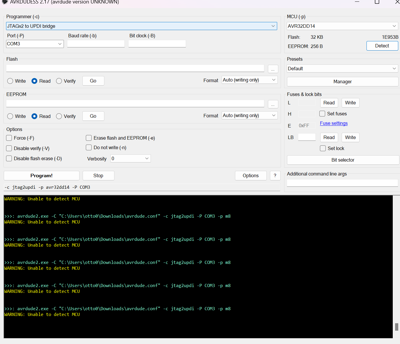
Softwareoberfläche und Kommandozeile von AVRDUDE
AVRDUDESS 2.17 (avrdude version UNKNOWN) Programmer (-c) MCU (-p) JTAGV2 to UPDI bridge Flash 32 KB Port (-P) COM3 Baud rate (-b) EEPROM 256 B Detect Write Read Verify Go Format Auto (writing only) Fuses L H LB Read Write Set fuses Set lock Options Force Erase flash and EEPROM (-e) Disable verify
in „UPDI Programmierung mit dem Diamex“ · Mikrocontroller und Digitale Elektronik · · Screenshots
-
Datei
AVRxt.asm
.include "AVR64EA28def.inc" ;.include "AVR128DA28def.inc" ;.include "AVR64EA28def.inc" ;.include "AVR16EB28def.inc" ;.include "AVR32DD28def.inc" ;.include "m4809def.inc" .equ DIR_LED = VPORTA_DIR .equ IN_LED = VPORTA_IN
in „AVR64EA28: PIT-Interrupt“ · Mikrocontroller und Digitale Elektronik ·
-
Datei
AVRxt.asm
; SLdt 2405070930 Interrupt auf AVR64EA28 ; avrasm2 .include "AVR64EA28def.inc" /* f [kHz]: live TCA TCB .include "AVR128DA28def.inc" ; 666 31 31 .include "AVR64EA28def.inc" ; 550 0 0 .include "AVR16EB28def.inc" ; 555 * 26 *: hat keinen TCA .include "AVR32DD28def.inc" ; 667 31 31 */ .equ dir = VPORTA_DIR .equ toggle = VPORTA_IN .equ ISR_TCA = 5 .equ ISR_TCB = 6 .equ f_live = 7 .def tmpi = r4 .def tmp0 = r16 ;=============== .org 0 rjmp reset .org TCA0
in „AVR64EA28: PIT-Interrupt“ · Mikrocontroller und Digitale Elektronik ·
-
Datei
main.asm
; File: tn12-isp-simulator\main.asm ; Device: AVR64DD32 ; Created: 2025-01-28 ; Version: 2025-02-03 ; Author: Johannes Fechner ; Select whether to output debug messages via USART0: .equ DEBUG = 1 ;.include "C:\Program Files\Microchip\MPLABX\v6.20\packs\Microchip\AVR-Dx_DFP\2.4.286\avrasm\inc\AVR64DD32def.inc" .include "macros.inc" .equ SIMFLASH_SIZE = 1024 ; CPU clock frequency: .equ F_CPU = 20_000_000 ; Hz ; SPI for communication with host/"programmer": .equ SPI_VDIR
in „AVR64DD32, UART-Ausgabe bleibt hängen, Assembler“ · Mikrocontroller und Digitale Elektronik ·
-
PDF
harman_kardon_avr145_sm.pdf
CHG1A160Z 1 S16 SCREW,SPECIAL CHD3A012R 6 44 BADGE ASS'Y CGX1A375ZA 1 1 ORNAMENT,BADGE CGX1A375M7G32 1 4 S17 SCREW,SPECIAL CHD4A012R 5 2 BADGE,H/K(TOP) KGB1A159Z 1 45 HEAT SINK CMY1A249 1 3 1 31 2 AVR145 harman/kardon 32 AVR145 harman/kardon AMPLIFIER SECTION BIAS ADJUSTMENT Measurement condition .No
in „Relais beim AVR 145 von harman/kardon durch SSR ersetzen“ · Analoge Elektronik und Schaltungstechnik ·