oropening G4IDC5G* [OBSOLETE] G4 DC Input 35–60 VDC, 5 VDC (SWNC). [OBSOLETE] Logic G4 DC Input 2.5–16 VDC, 5 VDC Logic Very Typical applications for DC input modules include sensing the G4IDC5K High Speed presenceor absence of voltageand sensingcontactclosurefrom sourcessuchasproximity switches,limit
So, ich habe den GAL (16V8D) "ausgelesen", ob das was sinnvolles ist, keine Ahnung, vermute aber, das ist Bullshit. Andererseits hat ELV schon so manchen Kunstgriff gemacht um extra programmierte Chips zu verkaufen. Aus Erzählungen
Old P. schrieb im Beitrag #8019943: > So, ich habe den GAL (16V8D) "ausgelesen", ob das was sinnvolles ist, > keine Ahnung, vermute aber, das ist Bullshit. M.E. sind da zu viele '1'en in den jedec-Daten. Die geschützte Firmware bzw. die 'Spezialchips' von ELV
) *Prüfung der 12V ud 8,2V am FBAS Encoder IC1 Pin 14, 16. 12V leicht HF-verrauscht, ca. 150mVpp. 8,2V deutlich sauberer, ca. 20mVpp *Ich habe versucht, die Zeilen selber mit dem Oszi anzuschauen, mein Oszi hat Video-Trigger. Wenn man die Zeilenzahl hochdreht
ist er nur 30 Jahre gealtert? Ich habe versuchsweise 100nF an IC1 Pin 14 gegen GND (Pin15) und Pin 16 gehalten, keine Änderung. Habt ihr Ideen?
VCC 14 Power supply pin for the IC; +12, 〉2.0 V, required at 35 mA (typical). Gnd 15 Ground pin. VB 16 8.2 V reference from an internal regulator capable of delivering 10 mA to external circuitry. Osc 17 Oscillator input. A transistor base preseto an external subcarrier input, or is available for in constructing
00000028 T HAL_SYSTICK_Config 08000387 00000008 T HAL_SYSTICK_IRQHandler 08001b35 00000060 T HAL_TIM_Base_Init 08003225 0000004e T HAL_TIM_Base_MspInit 08001b99 00000002 W HAL_TIMEx_Break2Callback 08001b97 00000002 W HAL_TIMEx_BreakCallback 08001b95 00000002 W HAL_TIMEx_CommutCallback 08001e83 00000004
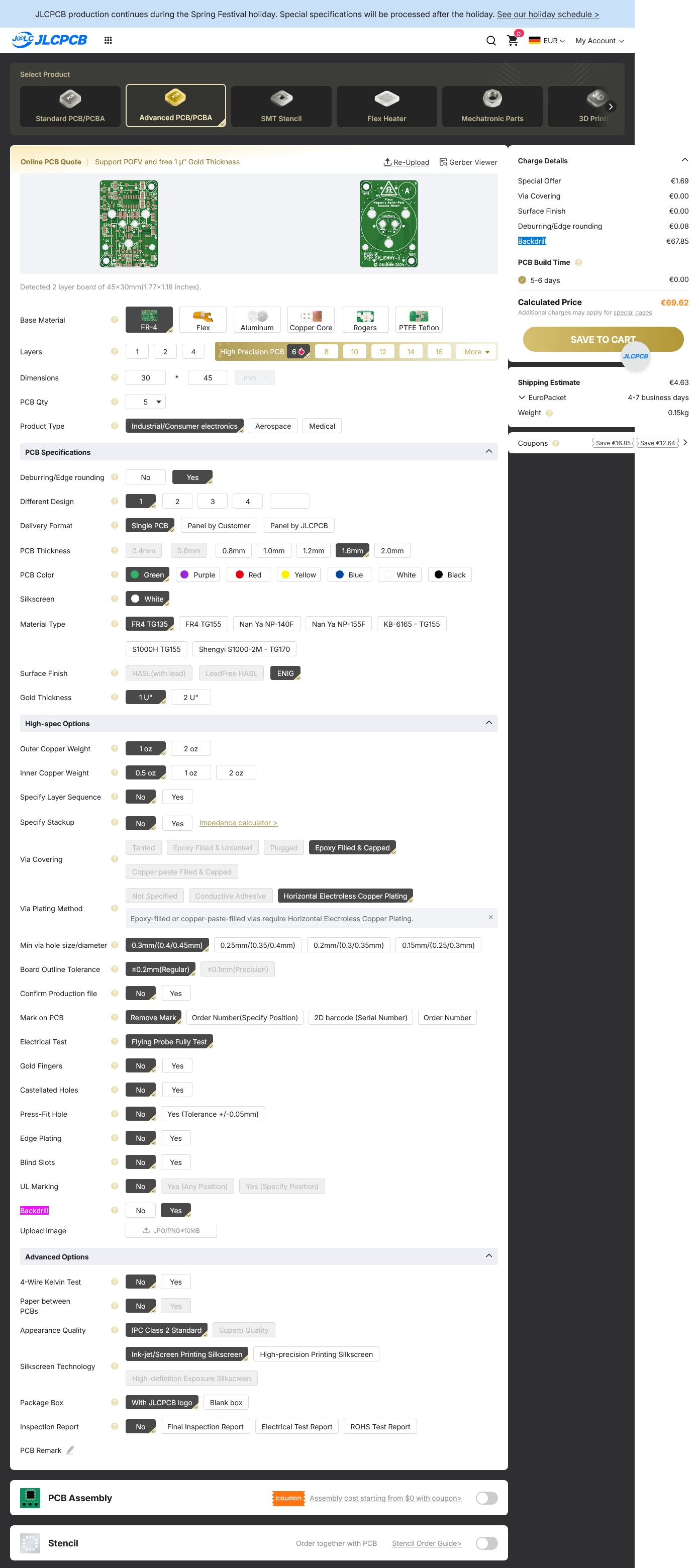
Build Time 5-6 days €0.00 Calculated Price €69.62 Shipping Estimate €4.63 Weight 0.15kg Coupons Save €16.00 Save €12.40 Base Material Dimensions Layers PCB Qty Product Type PCB Specifications Deburring/Edge rounding Different Design Delivery Format Single PCB Panel by Customer Panel by JLCPCB PCB Color
Au swahll der ingangsimpedanzE 1-15- Einstellungvo ninga ngskanal- riggerpegelZ-EmpfindUchkeitt 1-16 ÄnderungderTrig er-Betriebsart 1-16 -16 Mod ifizierungdes Eingangss- riggerpegels 1-17 Aus wahll der Eingangs-Trig erflanke 1-19 Aus wahll der Eingangsempfindhchkeit 1-19- 9 Einleitung der Messung 1-
Billion/Milliarde): Ein 7B-Modell hat 7 Milliarden Parameter. Präzision (Bit/Datentyp): Klassisch 16-Bit (FP16/BF16) = 2 Byte pro Parameter. Quantisierung (INT8 oder INT4) reduziert den Bedarf drastisch auf 1 Byte oder 0,5 Byte pro Parameter. Große Modelle (z.B. 70B+, z.B. Llama 3 70B): 16-bit: ~
lokalen Gegebenheiten nicht garantieren konnten. Die nächste Stufe darunter war zu dem Zeitpunkt wohl 16 MBit.
hast du selbst den Beweis für meine letzte Vermutung geliefert, dass > du nämlich einen Vertrag für 16 Mbit/s hast, für den du das zahlst, Wieso habe ich dann NICHT den Vodafone GigaHome 16 DSL Vertrag, Wieso habe ich einen Vodafone GigaHome 50 DSL und keinen Vodafone GigaHome 16 DSL?!? Ach komm, ich
Low Low Low, medium Peak Torque Up to 3611 lb-in (408 Nm) Up to 2257 lb-in (255 Nm) Up to 144 lb-in (16.2 Nm) Up to 301 lb-in (34 Nm) Base Speeds Up to 6000 rpm Up to 6000 rpm Up to 5000 rpm Up to 5000 rpm Brake Options 24 Vdc Holding Brake MS or circular style Circular style Circular style frame mounted
aus zuverlässiger Quelle. Z.B. kostet eine Samsung 32GB PRO Endurance microSD gerade mal 9€, eine 16GB 13€ usw. Bei anderen Herstellern wird das nicht anders sein. Und dann gibt's ja auch noch Industrial Karten.
Modules in Verbindung mit einem passenden IO-Board wie das hier https://www.waveshare.com/wiki/CM4-IO-BASE-B So habe ich einerseits EMMC statt SD fürs Betriebssystem plus eine M.2 für Daten plus RTC mit Batterie. Für CM5 gibts auch passende Boards. fchk
20k-Poti verwenden - gibt es, ist aber eher unüblich. Die 4 Spannungsquellen in Reihe zu den Basen sind nur zu testzwecken (flat(2m) bedeutet, dass bei jedem Simulationslauf die Spannung zufällig gleichverteilt zwischen -2mV und +2mV festgelegt wird) um nachzuvollziehen, wie groß die Abweichungen
Universalnichtskönner 555... Wenn man sowieso nur ein Rechteck im Auge hat, wäre der NCO eines PICs (12F1501, 16F1503, 16F1507-9) einen Blick wert.
Voltage (for ULN2002A/D - 2003A/D - 2004A/D) 30 V Ic Continuous Collector Current 500 mA Ib Continuous Base Current 25 mA Tamb Operating Ambient Temperature Range – 20 to 85 ⋅C T stg Storage Temperature Range – 55 to 150 ⋅C Tj Junction Temperature 150 ⋅C THERMAL DATA Symbol Parameter DIP16 SO16 Unit Rth j-amb
PHOTOGRAPHIC FILMS AND PRINTS. Film developing and darkroom printing both require that into the paper base and therefore need longer washing the negatives or prints be adequately washed to ensure times. longevity of the images. Many wash systems consume fresh water in a total loss situation. Whilst this
The regulator voltage is provided by a PNP pass transistor controlled by GRM32ER71C226KE18 (22 mF, 16 V, X7R, 1210), GRM31CR71C106KAC7 (10 mF, 16 V, X7R, 1206). an error amplifier with a bandgap reference, which gives it the lowest possible dropout voltage. The output current Calculating Bypass Capacitor
Repeater/Node pin (38) is latched into this bit at power-up/reset 1 = Repeater mode 0 = Node mode 16.10 TX 1, RW 100BASE-TX Mode Control 1 = 100BASE-TX operation 0=100BASE-FX operation 16.9 FEF 0, Rw Far End Fault Enable: Control the Far End Fault mechanism Associated with 100BASE-FX operation 28 Final
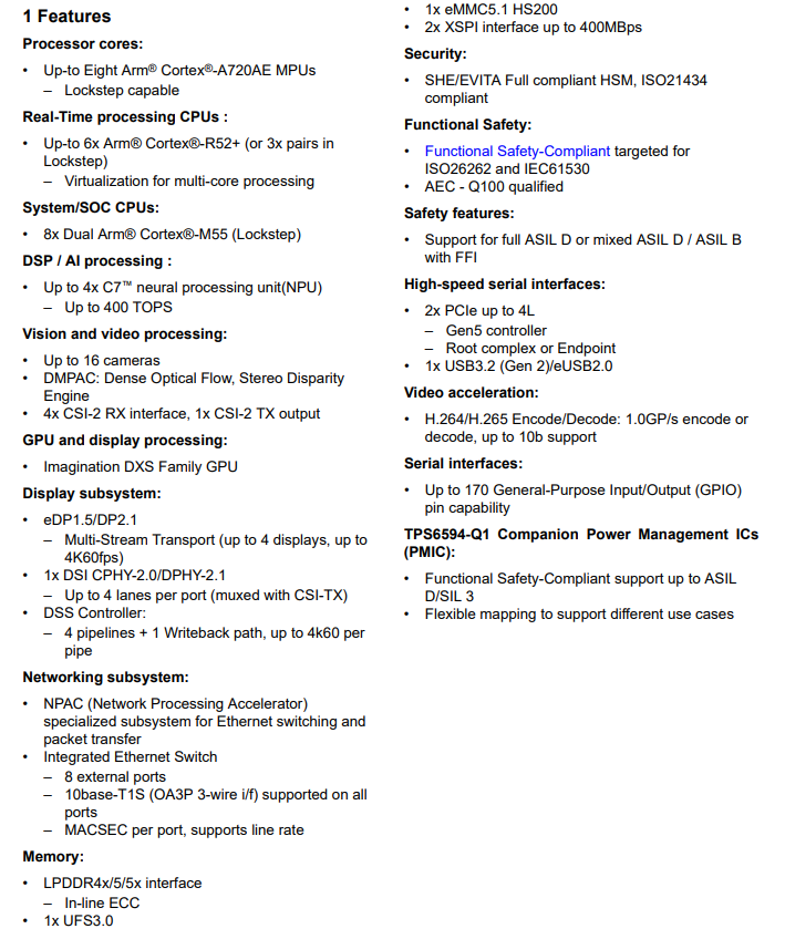
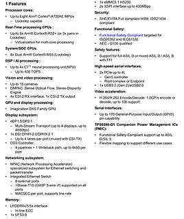
processing:
Up to 4x C7™ neural processing unit(NPU)
Up to 400 TOPS
Vision and video processing:
Up to 16 cameras
DMPAC: Dense Optical Flow, Stereo Disparity Engine
GPU and display processing:
4x CSI-2 RX interface, 1x CSI-2 TX output
Display subsystem:
eDP1.5/DP2.1
Multi-Stream Transport (up to 4 displays
Support 1b 1 = 100BASE-TX full duplex is supported by the local device 0 = 100BASE-TX full duplex is not supported 7 TX_HDX RW 100BASE-TX Support 1b 1 = 100BASE-TX half duplex is supported by the local device 0 = 100BASE-TX
Support 1 = 100BASE-TX full duplex is supported by the local device 0 = 100BASE-TX full duplex is not supported 7 TX_HDX 1, RW 100BASE-TX Support 1 = 100BASE-TX half duplex is supported by the local device 0 = 100BASE-TX
Figure8.SaturationVoltagevs.CollectorCurrent Figure10.TotalNoisevs.CollectorCurrent 100 20 ) F18 ( E C16 ) A H I14 √ C n P ( 10µA A12 T C S 10 S10 N A E - D O 8 I - O R 6 N T C 1mA L 4 L O 2 C 1 9 0 1 1 10 100 1k 10k - 0 1 2 3 4 5 6 7 8 9 10 - 4 0 FREQUENCY (Hz) 0 COLLECTOR-TO-BASE VOLTAGE (V) 0 Figure9.NoiseVoltageDensityvs.Frequency Figure11.Collector-to-BaseCapacitancevs.Collector-to-BaseVoltage Rev.A | Page 6of 12 MAT14 ) 40 10 F ( E 35 N A I 30 1 A P ) A n C 25 ( T N A E T 20 R 0.1 S U U C S 15 C O I - R 10 0.01 T C E 5 L O C 0 0.001 0 1 2 3 4 5 6 7 8
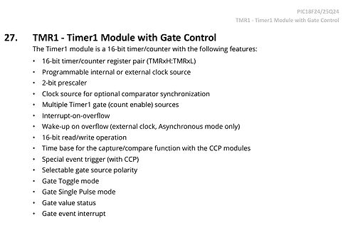
Module with Gate Control
PIC18F24/25Q24
TMR1 - Timer1 Module with Gate Control
The Timer1 module is a 16-bit timer/counter with the following features:
• 16-bit timer/counter register pair (TMRxH:TMRxL)
• Programmable internal or external clock source
• 2-bit prescaler
• Clock source for optional comparator
https://www.banggood.com/MUSTOOL-G1200D-Digital-Microscope-12MP-7-Inch-Large-Color-Screen-Large-Base-LCD-Display-1-1200X-Continuous-with-Light-p-1896503.html das ist ohne hdmi ausgang oder?
Bildformate für die Speicherung auf SD-Karte haben ein Seitenverhältnis von 4:3, der Sensor hat aber 16:9. Bei der Konvertierung werden die Bilder aber nicht beschnitten, sondern in x- und y-Richtung unterschiedlich skaliert, so dass ein Kreis im Screenshot als Ellipse erscheint. Das einzige Format,
AMPERE DARLINGTON ÎÎÎÎÎCollector–Emitter Voltage V 60 ÎÎ80 Vdc CEO POWER TRANSISTORS ÎÎÎÎÎCollector–Base Voltage V 60 ÎÎ80 Vdc COMPLEMENTARY CB ÎÎÎÎÎEmitter–Base Voltage V 5.0 ÎÎÎ Vdc SILICON EB 60–80 VOLTS ÎÎÎÎÎCollector Current ÎÎ I 10 Adc C 150 WATTS ÎÎÎÎÎBase CurrentÎÎÎÎÎ ÎÎ I 0.2 Adc B ÎÎÎÎÎTotal
MountingDimensions(for1-diskmodels) 100.350-0.250 69.850±0.250 (22.450) (13.430) (3.▯▯0) 2.499±1.270 7.949±1.270 (16.520) (90.600) BASE (14.000) 2X M3 X 0.5-6H 2X (3.000) MOUNTING HOLES: BOTH SIDES 7.000 0.200 MIN 3MM FULL THD BOTH SIDES 3.505+.075-.3X90 (90.600) (4.070) BASE (14.000) (61.720) 4X M3 X 0.5-6H MIN 23.505
Jitter 0.03 UI (combined residual jitter of reference generator and main receiver, with 120 Hz time-base bandwidth) 1–16 AM700 Audio Measurement Set Service Manual Specifications Table 1–5: Digital audio unit specifications (cont.) Capabilities Description Receiverinterface parameter measurements Phase
Junction-to-top characterization parameter 0.9 °C/W ψJB Junction-to-board characterization parameter 16.8 °C/W R Junction-to-case (bottom) thermal resistance 3.6 °C/W θJC(bot) (1) For more information about traditional and new thermal metrics, see the Semiconductor and IC Package Thermal Metrics application
M820) konfrontiert, der in den Bytes 14 und 15 offensichtlich eine zweite Checksumme erwartet. Die CRC16 an Bytes 16 und 17 wird berechenet wie oben schon herausgefunden. Kann jemand die Bytes 14 und 15 in dieser Datei zuordnen? https://github.com/EBiCS/BAFANG_GD32F303RCT6/raw/refs/heads/M560/documentation
Hochsitz C. schrieb im Beitrag #8038933: > Hat sich geklärt, das ist die Anzahl der Bytes minus 2^16 Wahrscheinlich eher modulo 2^16, also die letzten vier Hexadezimal-Stellen.
Folie ... Und den Ace konnte man, wenn man den HF-Modulator entfernte, auch an einem Monitor mit BAS-Eingang betreiben. Ich muss zugeben, ich hab' keine Idee davon, wie das mit einem Composite-zu-HDMI-Adapter an einem heutigen Monitor aussieht ... mein Bedarf, einen damals schon praktisch unbenutzbaren
MHz, die ein Fernseher hinbekam. Mein nächster Computer nutzte ein Selbstbau-Graphikterminal mit 16 MHz Pixeltakt - das konnte man auf dem reduzierten Fernseher durchaus noch erkennen, aber das Ding flackerte doch arg (sehr kurze Nachleuchtdauer des Leuchtstoffs), und wie gesagt, linear und verzerrungsfreies

 Bild
Bild
 Bild
Bild
 Bild
Bild
 Bild
Bild
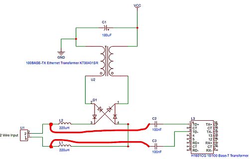
 Bild
Bild

 Bild
Bild

 Bild
Bild
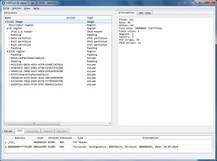
 Bild
Bild
 Bild
Bild