-
PDF
MCAC75N06YBTP-datasheet-3.pdf
60 V Gate-Source Leakage Current GSS V DSV, V GS=±20V ±100 nA Zero Gate Voltage Drain Current DSS V DS8V, V =GS 1 µA Gate-Threshold Voltage V V =V , I =250µA 2 4 V GS(th) DS GS D Drain-Source On-Resistance R DS(on) V GS0V, I D20A 5 6 mΩ Diode Characteristics Continuous Body Diode Current S 75 A Diode
in „Suche Ersatz für obsoleten MOSFET MCAC75N06YB-TP (oder Bezugsquelle)“ · Analoge Elektronik und Schaltungstechnik ·
-
PDF
xminilab-manual.pdf
option (bitfield): Bit 0: Serial Hex Display Bit 1: Parallel Hex Display Bit 2: I2C decoding Bit 3: RS232 decoding Bit 4: SPI decoding Bit 5: Use ASCII with RS232 6.2.3 General settings (10 bytes) 1) Trigger, Cursors Bit 0: Free trigger * Bit 1: Normal trigger * Bit 2: Single trigger * Bit 3: Auto trigger
in „USART - xmodem (Xminilab) - Bildübertragung“ · Mikrocontroller und Digitale Elektronik ·
-
PDF
xminilab-manual.pdf
option (bitfield): Bit 0: Serial Hex Display Bit 1: Parallel Hex Display Bit 2: I2C decoding Bit 3: RS232 decoding Bit 4: SPI decoding Bit 5: Use ASCII with RS232 6.2.3 General settings (10 bytes) 1) Trigger, Cursors Bit 0: Free trigger * Bit 1: Normal trigger * Bit 2: Single trigger * Bit 3: Auto trigger
in „ATXmega32 flashen mit ATMEL Flip (Xminilab)“ · Mikrocontroller und Digitale Elektronik ·
-
Datei
main.c
_test2; standard_t *standard= (standard_t *) malloc(sizeof(standard_t));; delay_init(); init_dbg_rs232(FPBA); twi_init(); board_init(); sysclk_init(); init_spi(); dip204_init(); gpio_init(); read_bq34z100_standard(standard); ds1307_write_byte(0x00, 0x00 & CH); dip204_clear_display(); dip204_set_cursor_position
in „AVR32 Timer Interrupt“ · Mikrocontroller und Digitale Elektronik ·
-
PDF
DS1000Z_Firmware_Release_Notes-7.pdf
Instrument Firmware Release Notes Models DS1054Z, DS1074Z, DS1104Z, DS1054Z-S, DS1074Z-S, DS1104Z-S, MSO1074Z, MSO1104Z, MSO1074Z-S, MSO1104Z-S Version Information Released version: 00.04.03.02.03 Release Date: 10/20/2015 Compatibility Compatible
in „Rigol-DS1054Z“ · Mikrocontroller und Digitale Elektronik ·
-
PDF
lg_flatron_l1800p_lb886f_ch_cl-29.pdf
0CC101CK41A 100PF160850V5%R/TPNP0 D504 0DS301109AA MMBD301LT1TPMOTOROLASOT23 C517 0CC101CK41A 100PF160850V5%R/TPNP0 D701 0DS226009AA KDS226 TPKECSOT-2380V30 C519 0CC101CK41A 100PF160850V5%R/TPNP0 D702 0DS226009AA KDS226 TPKECSOT-2380V30 C520
in „Überspannung in Mehrparteien-Wohunung. Baustrom, oder Kabel angebohrt?“ · Haus & Smart Home ·
-
Datei
1wire_irq.c.txt
buffer, 0x0, 0x0, &time)) { counter_10ms_32bit=100*time; } return 1; } } } return 0; } //#if funcused ds2430_reset // ******************************************************************************** // Description : resets all register // Input : 1.) *romcode - pointer to 9Byte-Array with ROM-number //
in „Mit MSP430 einen IC( bq2023) programmieren“ · Mikrocontroller und Digitale Elektronik ·
-
PDF
Datenblatt.pdf
FT232BL USB UART ( USB - Serial) I.C. 7.3 USB Bus Powered and Self Powered Conguration Figure 7 USB Bus Powered Conguration ������� ���� ���� ��� ��� ��� ��������� � ��� � � �� �� �� ����� � ������� � �
in „Entstörung einer USB Spannungsquelle“ · Mikrocontroller und Digitale Elektronik ·
-
Datei
main.c
------------------------- Author: Patrick Spöde Remarks: known Problems: Empfangene Daten an der RS232 werden erst ins UDR geschrieben, wenn das nächste Zeichen empfangen wird. Kann man das Receive Shift Register deaktivieren? Wenn ich ein Befehl sende, brauche ich unbedingt die Antwort direkt im Speicher
in „1-Wire Atmega8 <-> DS2480B UART Problem“ · Haus & Smart Home ·
-
PDF
steute.pdf
Nr. RF 95 WHKM EN868 95918001 Drehhebel D Typ Best.-Nr. RF 95 D EN868 95921901 Stellbarer Drehhebel DS Typ Best.-Nr. RF 95 DS EN868 95929001 Druckdatum: Seite steute SchaltgeräteBrückenstraße 91 Telefon +49 (0) 5731 745-0 inf@ steute.com 2012-06-29 4 / 10 GmbH & Co. KG 32584 Löhne, DeutschlandTelefax
in „Übertragung von drei Schaltsignalen über 20m“ · HF, Funk und Felder ·
-
Datei
Values.txt
MAX700CPA 1 MAX6325 1 MAX-485 1 MAX4102ESA 1 MAX4029EWP 1 MAX3232 1 MAX3226EEAE 1 MAX3222 1 MAX233 RS232-Konverter 1 MAX232_TI 1 MAX232A 1 MAX211CAI 1 MAX202ECWE 1 MAX202 1 MAX1818EUT 1 MAX1722 1 MAX1551 1 MAS3507D 1 MAC64L 1 M24C64 1 M09S 1 M001 1 LY5150AL 1 Lüfter 4 1 Lüfter 3 1 Lüfter 2 1 Lüfter 1 1
in „[KiCad] Bibliotheksaufbau - Konzeptideen gesucht“ · Platinen ·
-
PDF
sam7s_user_guide.pdf
AT91SAM7S-EK Board 2.5 AT91SAM7S-EK Figure 2-1. Block Diagram for AT91SAM7S-EK Board Block Diagram Analog RS232 RS232 Inputs Driver Driver 4 User Pushbuttons User LEDs Crypto Memory UART TWI DBGU 1.8V VDDCORE AT91SAM7S64 VDDOUT 3.3V NRST Pushbutton Oscillator, Extension Slot PLL 7 - 14V DC User Grid Input Power
in „AT91SAM7X64 SERIAL BOOTLOADER“ · Mikrocontroller und Digitale Elektronik ·
-
PDF
doc6112.pdf
AT91SAM7S-EK Board 2.5 AT91SAM7S-EK Figure 2-1. Block Diagram for AT91SAM7S-EK Board Block Diagram Analog RS232 RS232 Inputs Driver Driver 4 User Pushbuttons User LEDs Crypto Memory UART TWI DBGU 1.8V VDDCORE AT91SAM7S64 VDDOUT 3.3V NRST Pushbutton Oscillator, Extension Slot PLL 7 - 14V DC User Grid Input Power
in „AT91SAM7S-EK Nachbau“ · Mikrocontroller und Digitale Elektronik ·
-
PDF
TTL-232_RG_CABLES.pdf
provide a fast, simple way to connect devices with a logic level serial interface to USB. Each TTL-232RG generic cable contains a small internal electronic circuit board, utilising the FT232R, which is encapsulated into the USB connector end of the cable. The FT232R datasheet, DS_FT232R, is available
in „Leidiges Thema RS232!“ · Mikrocontroller und Digitale Elektronik ·
-
PDF
ESP32Radio.pdf
SP_L 1 3 2 +3.3V +5V SoundP Out R 11 14 J20 IN OUT U5 GND IN4 OUT4 C C3 D C7 1 9V 1 C G J5 L 2 TDA7439DS 10 2 S Eigene:TDA7439DS DIAGNOSTIC 330n 2 100n k 1 k 6 SVR S18 0 R20 0 V BO-R 13 100n C41 7 SP_R GND 1 1 22 12 100n C45 St-By 10k STANDBY SDA BI-R 2 PWGND 8 2 3 21 SCL MO-R 11 22n C35 R L 4 9 Q7 BSS138
in „TDA7439DS Störgeräusche und ein kochender TDA7377“ · Mikrocontroller und Digitale Elektronik ·
-
PDF
MGA-62563__AV02-1237EN_.pdf
power sup- Vd ply, while internal feedback ensures stability (K>1) over all frequencies. Ibias Id =ds +bias PinConnectionsandPackageMarking Rbias Ids V Feedback bias 4 Input 6 match 3 RFout RFin OUTPUT Bias GND 1 6 6 and d 2 GND 2 x 5 GND 1, 2, 5 INPUT 3 4 BIAS GND Note: Package marking provides orientation
-
Datei
test.ino.asm
:write_high: if (msg.data[msg.position] & (1 << i)) { 2c8: 20 91 62 01 lds r18, 0x0162 ; 0x800162 <ds+0x9> 2cc: 30 91 59 01 lds r19, 0x0159 ; 0x800159 <ds> 2d0: e0 91 5f 01 lds r30, 0x015F ; 0x80015f <ds+0x6> 2d4: f0 91 60 01 lds r31, 0x0160 ; 0x800160 <ds+0x7> 2d8: e2 0f add r30, r18 2da: f1 1d adc
in „Atmega328 1-Wire mit Timer CTC/PWM“ · Mikrocontroller und Digitale Elektronik ·
-
 Bild
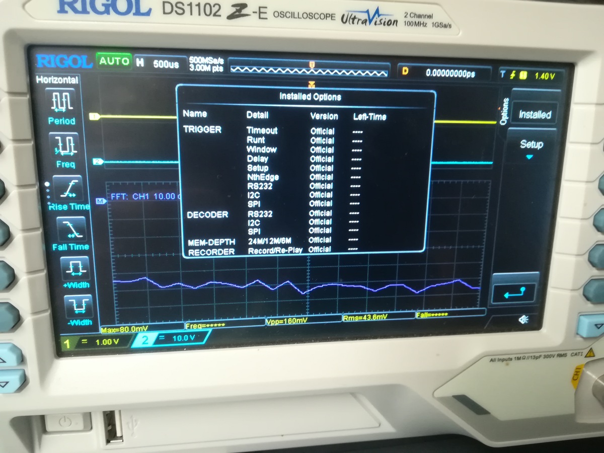
Abfotografiertes Rigol DS1102Z Oszilloskop Display mit Menü
RIGOL DS1102Z-E OSCILLOSCOPE UltraVision 2 Channel 100MHz 500MSa/s Installed Options Name Detail Version Left-Time TRIGGER Timeout Runt Window Delay Setup NthEdge RS232 Official DECODER I2C SPI RS232 I2C SPI
in „[V] Rigol DS1102Z-E Digital-Oszilloskop 100 MHz 2-Kanal 1 GSa/s 24 Mpts 8 Bit“ · Markt · · Fotos
-
PDF
AN162.pdf
the DS18X20/DS1822 1-Wire® temperature sensor in a microcontroller environment Abstract: This application introduces the user to simple 1-Wire software for interfacing a microcontroller to the DS18B20, DS18S20
in „Temperaturfühler identifizieren“ · Analoge Elektronik und Schaltungstechnik ·
-
PDF
camaro_stand_alone.pdf
D PD7 2 N 2,2k +5V GND5 +5V 7 k 2 N D 1 3 2 1 , 1 G S R 4 8 R3 220 I 4 1 Luefter2 0 0 0 M J1 1 1 1 DS18B20 R11 X X X DS1820 OK2 V GND + C C Brake und Getriebetemp Eingänge Wahlhebel GND GND X3A Thermistor X4A PSWITCH-N 2,7k J5 +5V +5V Gehäuselüfter kommt vom thermistor X3B 1 4 X4B PSWITCH-R R5 2 0 Brake
in „Stn1110 am atmega2560 uart probleme“ · Mikrocontroller und Digitale Elektronik ·
-
Datei
katzd.c
pid=%d", pid); return; } if (WIFEXITED(status)) message(DEBUG, &now_tm, "%schild %d: exited after %ds - return code %d", child_prefix, (pid_t)pid, (int)rtime, (int)WEXITSTATUS(status)); else if (WIFSIGNALED(status)) message(DEBUG, &now_tm, "%schild %d: terminated after %ds by signal %d", child_prefix
in „RFID Tierchip auslesen für Katzenklappe(Pollin Board)“ · Mikrocontroller und Digitale Elektronik ·
-
PDF
app162__Interfacing_DS1820_in_a_MC_environment_.pdf
for the TM Wire devices such as the DS18B20, DS18S20 or DS18B20, DS18S20 and DS1822 is available in their DS1822 to a microcontroller. These methods range respective datasheets, which can be obtained from from simple software solutions, to
in „DS18B20 zu komplizierte Ansteuerung?“ · Mikrocontroller und Digitale Elektronik ·
-
PDF
app162__Interfacing_DS1820_in_a_MC_environment_.pdf
for the TM Wire devices such as the DS18B20, DS18S20 or DS18B20, DS18S20 and DS1822 is available in their DS1822 to a microcontroller. These methods range respective datasheets, which can be obtained from from simple software solutions, to
-
PDF
CH340DS1.PDF
frequency interference, around the ground or pour copper around the relevant components. 7.2. USB to RS232 converter configuration (3-wire) The image below is USB to 3-wire RS232 converter design which is the most basic and most commonly used, U5 uses MAX232/ICL232/SP232 etc. 7.3. USB to RS232 converter configuration (simplified version using RS232) CH340 Datasheet 9 The image above is USB to RS232 converter design too, the function of this circuit is the same with 7.2 section except the range of output RS232 is narrower. When R232 pin is driven
in „CH340G meldet sich nicht als serielle Schnittstelle am PC (Windows)“ · Mikrocontroller und Digitale Elektronik ·
-
PDF
CH340_USB_UART.pdf
frequency interference, around the ground or pour copper around the relevant components. 7.2. USB to RS232 converter configuration (3-wire) The image below is USB to 3-wire RS232 converter design which is the most basic and most commonly used, U5 uses MAX232/ICL232/SP232 etc. 7.3. USB to RS232 converter configuration (simplified version using RS232) The image above is USB to RS232 converter design too, the function of this circuit is the same with 7.2 section except the range of output RS232 is narrower. When R232 pin is driven high, the assistant
in „FT232 lieferbar?“ · Mikrocontroller und Digitale Elektronik ·
-
 Bild
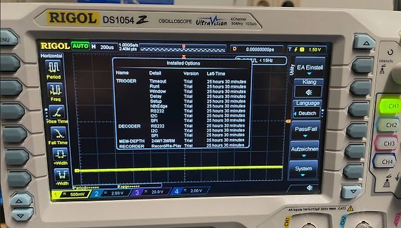
Oszilloskop mit Menüanzeige der installierten Optionen
RIGOL DS1054Z OSCILLOSCOPE UltraVision 50MHz 1GSa/s Horizontal AUTO 200us 1.00GSa/s Name Detail Version Left-Time TRIGGER Timeout Trial 25 hours 30 minutes Runt Window Trial 25 hours 30 minutes Delay Setup Trial 25 hours 30 minutes NthEdge Trial 25 hours 30 minutes RS232 I2C Trial 25 hours 30 minutes SPI I2C Trial 25 hours 30 minutes DECODER RS232 Trial 25 hours 30 minutes I2C SPI Trial 25 hours 30 minutes MEM-DEPTH 24M/12M/6M Trial 25 hours 30 minutes RECORDER Record
in „[V] Rigol DS1054Z“ · Markt · · Fotos
-
Datei
93c66.asm
********************************************************* #include equates.inc ORG $0800 ;RAM adr: DS $01 byte2: DS $01 byte3: DS $01 ORG $0D00 ;EEPROM HC912B32 MAIN: lds #$C00 CLR COPCTL BSR INIT ;Subroutine to initialize SPI+SCI registers ldx #Hello ;Text an RS232 JSR outstr jsr delay ldaa #0 staa
in „Motorola HC12 und Eeprom 93C66“ · Mikrocontroller und Digitale Elektronik ·
-
PDF
DE2012010361.pdf
Mainflinger DCF77-Senders herauszukitzeln, nutzt dieses Projekt DSP-Algorithmen in einem preiswerten dsPIC33- Controller. So wird das amplituden-und phasenmodulierte Signal gefiltert und demoduliert. Das Ergebnis ist ein sehr stabiles 10-Hz-Taktsignal. VonSteveMarchant(UK) DCF77-Empfänger stellen außerdem
-
PDF
VAR-DT6CUSTOMBOARD_SCH_V1_1_Doc_V1_2.pdf
UART_ENABLE 2 1DIR 1OE# 15 5 2 5 2 3 2DIR 2OE# 14 3 UART3_TXD 4 1A1 1B1 13 UART3_TX_B 11 T1IN T1OUT 14 RS232_TX 6 1 6 1 3 UART3_CTS 5 '0'- 12 UART3_CTS_B 10 7 RS232_RTS 3 UART3_RXD 6 1A2 B->A 1B2 11 T2IN T2OUT 7 2A1 2B1 10 UART3_RX_B 12 13 RS232_RX 3 UART3_RTS 8 2A2 A 2B2 9 UART3_RTS_B 9 R1OUT R1IN 8 RS232
-
PDF
Interfacing_the_Serial_RS232_Port.pdf
into your serial plug, typically a D-type connector. Therefore RS232 Level Converters (which we talk about in detail later) are used. These are commonly the DS1489 Receiver and the DS1488 as the PC has +12 and -12 volt rails which can be used by these devices. The RS232
in „fehlerfreie UART-Übertragung?“ · Mikrocontroller und Digitale Elektronik ·
-
PDF
SCHEMATIC1___PAGE1.pdf
BT1 13 10k R3A 1 2 T2CLK A15 29 X1 111 AVEC D5 131 D6 D6 8 1 R2G 3V VBAT2 R3B 1 3 BKPT A16 3 A14 BDM DS 110 RMC D6 130 D7 D7 9 1 R2H R3C 1 4 TSTME A17 2 A15 DS 1 2 BERR MISO 65 DS D7 127 D8 D8 2 1 R4A 10k R3D 1 5 RW A18 30 A16 C7 VCC 3 4 BKPT MOSI 66 MISO D8 125 D9 D9 3 1 R4B R3E 1 6 DSACK0 A19 1 A17 10n
in „Schaltung mit 68332“ · Mikrocontroller und Digitale Elektronik ·
-
PDF
40146F.pdf
PIC16F5xx), midrange and source code for examination and modification. (PIC12F6xx, PIC16F), PIC18F, PIC24, dsPIC30, Theboardssupportavarietyoffeatures,includingLEDs, dsPIC33, and PIC32 families of 8-bit, 16-bit, and 32-bit temperature sensors, switches, speakers, RS-232 microcontrollers, and many Microchip Serial
in „Fehlersuche Funksender Zentralverriegelung Toyota Yaris“ · Fahrzeugelektronik ·
-
PDF
datenblatt_pic.pdf
details of Serial Programming, please refer to the In-Circuit Serial Programming™ (ICSP™) Guide, (DS30277). 2001 Microchip Technology Inc. DS35007B-page 33 PIC16F84A NOTES: DS35007B-page 34 2001 Microchip Technology Inc. PIC16F84A 7.0 INSTRUCTION SET SUMMARY All instructions are executed within
in „Flußdiagramm Digitale stoppuhr auf PIC 16F84A“ · Mikrocontroller und Digitale Elektronik ·
-
PDF
16F84.pdf
details of Serial Programming, please refer to the In-Circuit Serial Programming™ (ICSP™) Guide, (DS30277). 2001 Microchip Technology Inc. DS35007B-page 33 PIC16F84A NOTES: DS35007B-page 34 2001 Microchip Technology Inc. PIC16F84A 7.0 INSTRUCTION SET SUMMARY All instructions are executed within
in „Probleme mit Taktversorgung auf Steckbrett“ · Mikrocontroller und Digitale Elektronik ·
-
Datei
OneWire.c
while(1); } // the first ROM byte indicates which chip switch (addr[0]) { case 0x10: printf("Chip = DS18S20"); // or old DS1820 type_s = 1; break; case 0x28: printf("Chip = DS18B20"); type_s = 0; break; case 0x22: printf("Chip = DS1822"); type_s = 0; break; default: { printf("Device is not a DS18x20 family
in „Böses One-Wire device“ · Mikrocontroller und Digitale Elektronik ·
-
Datei
2051.txt
|rs232|o-|-+ o| |o----|------+ +----------+ | | |o-+ +--o| |o--+ | | | ++----+ | | __|o +o|__|o----|------|----+ | | | | 1 | 1 | | | | | | 1 _ | | | | | 27 | | | +o| |o-------+---+ | +----+---+ | || | +-|-
in „Spikes im Lüftertachosignal unterdrücken“ · Mikrocontroller und Digitale Elektronik ·
-
PDF
CAN-BootloaderPIC18F.pdf
FOR CAN NETWORKS (POWER SUPPLY, DISPLAYS AND CONNECTION HEADERS) 2003 Microchip Technology Inc. DS00247A-page 13 AN247 FIGURE A-3: EXAMPLE DIALOGS FOR THE CANCOMM HOST SOFTWARE: OUTPUT STATUS MESSAGES (TOP) AND PROGRESS BAR (BOTTOM) DS00247A-page 14 2003 Microchip Technology Inc. AN247 Software
in „CAN-Bootloader für PIC18F“ · Mikrocontroller und Digitale Elektronik ·
-
Datei
ZndUhr01.asm
,5 ;5 Sekunden add dsl,wl adc dsh,null lds snr,snra ;alte Schussnummer inc snr ;plus 1 mp_4b: rjmp ds_korr1 mp_05: ;+/- 1 h ldi yl,low(3600) ;Intervall ldi yh,high(3600) ;1 Stunde ds_korr: ;Korrektur Zeitstempel Datensatz sbrs tfl,tho ;Taste hoch? ja... rjmp pc+3 ;nein... add dsl,yl ;ja, Intervall adc
in „Display Menü LCD 4x20“ · Mikrocontroller und Digitale Elektronik ·
-
PDF
W2000_deutsch.pdf
Mehrsprachige Bedieneroberfläche • Signal- und Setup-Speicherung • FFT Standard in allen Modellen • RS232 und USB-PC-Schnittstelle Die W2000 Serie tastet die Signale hochge- nau mit einer Echtzeitabtastrate von 1GSa/s • PC Software im Preis enthalten pro Kanal bei voller Analogbandbreite ab Digital gleich
in „Oszilloskope; USB VS Standgerät“ · Mikrocontroller und Digitale Elektronik ·
-
PDF
W2000_deutsch.pdf
Mehrsprachige Bedieneroberfläche • Signal- und Setup-Speicherung • FFT Standard in allen Modellen • RS232 und USB-PC-Schnittstelle Die W2000 Serie tastet die Signale hochge- nau mit einer Echtzeitabtastrate von 1GSa/s • PC Software im Preis enthalten pro Kanal bei voller Analogbandbreite ab Digital gleich
in „ist 1000 Euros für "Texktronix TDS 684A" gut?“ · Markt ·
-
PDF
W2000_deutsch.pdf
Mehrsprachige Bedieneroberfläche • Signal- und Setup-Speicherung • FFT Standard in allen Modellen • RS232 und USB-PC-Schnittstelle Die W2000 Serie tastet die Signale hochge- nau mit einer Echtzeitabtastrate von 1GSa/s • PC Software im Preis enthalten pro Kanal bei voller Analogbandbreite ab Digital gleich
in „Wittig(welec) DSO W20xxA Open Source Firmware (Teil2)“ · Mikrocontroller und Digitale Elektronik ·
-
PDF
doc6241-1369051.pdf
LED 2 PA3 TWD A3 High-Drive EEPROM AT24C256 (SDA) PA4 TWCK A4 EEPROM AT24C256 (SCL) PA5 RXD0 A5 RS232 COM PORT (RXD) PA6 TXD0 A6 RS232 COM PORT (TXD) PA7 RTS0 A7 RS232 COM PORT (RTS) PA8 CTS0 A8 RS232 COM PORT (CTS) PA9 DRXD A9 SERIAL DEBUG PORT(RXD) PA10 DTXD A10 SERIAL DEBUG PORT(TXD) PA11 NPCS0 A11
-
PDF
Display_Controller.pdf
X 160 SEG MF[2:0] I Manufacturer ID code for reference, suggestion setting [ MF2.MF1.MF0 = 0.0.0 ] DS[1:0] I Display size ID code for reference, suggestion setting [ DS1.DS0 = 1.0 or DS1.DS0 = 0.0] Ver2.3 17/97 2007/1/3 ST7528 MICROPROCESSOR INTERFACE Microprocessor Interface Pin Description Name I/O
in „LCD Controler mit Spannungsregulier-Eingängen“ · Mikrocontroller und Digitale Elektronik ·
-
Datei
atxmega_partlist.txt
REGULATOR IC3 LM358N LM358N DIL08 OP AMP also LM158; LM258; LM2904 IC5 ULN2803A DIL18 DRIVER ARRAY IC7 FT232RL FT232RL SSOP28 Source: http://www.ftdichip.com/Documents/DataSheets/DS_FT232R_v104.pdf IR_LED LED5MM LED5MM LED JP_CD+ JP1E JP1 JUMPER JP_CS JP1E JP1 JUMPER JP_DAC PINHD-1X2 1X02 PIN HEADER JP_DAC2 PINHD-1X2 1X02 PIN HEADER JP_DARL PINHD-2X4 2X04 PIN HEADER JP_FT232 JP4Q JP4Q JUMPER JP_GND PINHD-1X4 1X04 PIN HEADER JP_IRL JP1E JP1 JUMPER JP_JTAG AVR-JTAG-10 AVR-JTAG-10 AVR-JTAG-10 AVR JTAG Debug/Programming Header JP_LEDS PINHD-2X4 2X04 PIN HEADER JP_PDI PINHD-
in „Besteht Interesse an einfacher Experimentierplatine fuer den Xmega128a1?“ · Mikrocontroller und Digitale Elektronik ·
-
PDF
PIC12F508_Datasheet.pdf
mode. The MPLAB PM3 Microchip Fla®h DSC and MCU devices. It®debugs and programs PIC Flash MCUs and dsPIC Flash DSCs connects to the host PC via an RS-232 or USB cable. withtheeasy-to-use, powerfulgraphicaluserinterfaceof The MPLAB PM3 has high-speed communications and the MPLAB Integrated Development
in „Funktion Reifendruckanlerngerät EL-50448; OEC-T5; Welches Bauelement ist das?“ · Fahrzeugelektronik ·
-
PDF
PIC12F508.pdf
mode. The MPLAB PM3 Microchip Fla®h DSC and MCU devices. It®debugs and programs PIC Flash MCUs and dsPIC Flash DSCs connects to the host PC via an RS-232 or USB cable. withtheeasy-to-use, powerfulgraphicaluserinterfaceof The MPLAB PM3 has high-speed communications and the MPLAB Integrated Development
in „Funktion Reifendruckanlerngerät EL-50448; OEC-T5; Welches Bauelement ist das?“ · Fahrzeugelektronik ·
-
PDF
DM8603EP.pdf
Ethernet Switch Controller with MII / RMII Interface DATASHEET Preliminary Datasheet Version: DM8603-DS-P01 November 8, 2010 Preliminarydatasheet 1 DM8603-12-DS-P01 November8,2010 Downloaded from Elcodis.com electronic components distributor DM8603 10/100Mbps3-portEthernetSwitchControllerwithMII/RMIIInterface
in „2 Port Switch IC wie in IP telefonen?“ · Mikrocontroller und Digitale Elektronik ·
-
PDF
DM8603EP.pdf
Ethernet Switch Controller with MII / RMII Interface DATASHEET Preliminary Datasheet Version: DM8603-DS-P01 November 8, 2010 Preliminarydatasheet 1 DM8603-12-DS-P01 November8,2010 Downloaded from Elcodis.com electronic components distributor DM8603 10/100Mbps3-portEthernetSwitchControllerwithMII/RMIIInterface
in „[V] DM8203 & DM8603“ · Markt ·
-
Datei
beispiel.html
LPC2148 </b></span> OK </li> </ul> kicadlib.org/zip/lqfp64_05.emp.zip <br> <ul> </ul> kicadlib.org/zip/mm232r.lib.zip <br> <ul> <li><b> mm232r.lib </b> 845 Bytes - <span style="color: blue;"><b> MM232R </b></span> OK </li> </ul> kicadlib.org/zip/mm232r.mod.zip <br> <ul> </ul> kicadlib.org/zip/msp430.lib.zip
in „[KiCad] Bibliotheksaufbau - Konzeptideen gesucht“ · Platinen ·