
-
PDF
Designing_Photodiode_Amplifier_Circuits.pdf
considered if wide temperature range operation is ex- Responsivity –5 X 10 V/W 0.5pF pected. The OPA128LM specs only 2pA max at +70°C. Bandwidth 100kHz Bias current also causes shot noise. Offset Voltage±1mV 1M i = 2qi S UDT Pin-040A or q: 1.602 x 10 –19coulombs SDC SD-041-11-21-011 2 i: bias (or signal
-
PDF
Fotodiode_applications.pdf
considered if wide temperature range operation is ex- Responsivity –5 X 10 V/W 0.5pF pected. The OPA128LM specs only 2pA max at +70°C. Bandwidth 100kHz Bias current also causes shot noise. Offset Voltage±1mV 1M i = 2qi S UDT Pin-040A or q: 1.602 x 10 –19coulombs SDC SD-041-11-21-011 2 i: bias (or signal
in „Beschaltung von Photodioden“ · Mikrocontroller und Digitale Elektronik ·
-
PDF
Fotodiode_applications.pdf
considered if wide temperature range operation is ex- Responsivity –5 X 10 V/W 0.5pF pected. The OPA128LM specs only 2pA max at +70°C. Bandwidth 100kHz Bias current also causes shot noise. Offset Voltage±1mV 1M i = 2qi S UDT Pin-040A or q: 1.602 x 10 –19coulombs SDC SD-041-11-21-011 2 i: bias (or signal
in „Suche Strom-Widerstandswandler“ · Mikrocontroller und Digitale Elektronik ·
-
Datei
ci_slot_1_satip_slot_2.txt
- AuxPwr- NoSnoop- MaxPayload 128 bytes, MaxReadReq 512 bytes DevSta: CorrErr- UncorrErr- FatalErr- UnsuppReq- AuxPwr- TransPend- LnkCap: Port #0, Speed 2.5GT/s, Width x1, ASPM L0s, Exit Latency L0s unlimited, L1 <1us ClockPM
in „PCI-Express-Slots defekt bzw. zerstört?“ · PC Hard- und Software ·
-
Datei
satip_slot_1_ci_slot_2.txt
- AuxPwr- NoSnoop- MaxPayload 128 bytes, MaxReadReq 512 bytes DevSta: CorrErr- UncorrErr- FatalErr- UnsuppReq- AuxPwr- TransPend- LnkCap: Port #0, Speed 2.5GT/s, Width x1, ASPM L0s, Exit Latency L0s unlimited, L1 <1us ClockPM
in „PCI-Express-Slots defekt bzw. zerstört?“ · PC Hard- und Software ·
-
PDF
IC1210-F128LQ_Datasheet.pdf
Speed DPLUS/DMINUS Pins DC Electrical Characteristics Integrated Circuit Solution Inc. 12 IC1210-F128LQ 7.2. USB AT HIGH SPEED Parameter Conditions Min. Nom. Max. Units Differential Input 0.2 V Common Mode 0.8 2.5 V Squelch Differential Threshold 0.8 V Un-Squelch Differential 2.0 V Threshold Low Level
in „MCS-52 (IC1210-F128LQ)“ · Mikrocontroller und Digitale Elektronik ·
-
PDF
dogm128.pdf
Stand 8.2007 DOGM GRAFIK SERIE 128x64 PIXEL leferar ! h ab1 Stck 5,6mm fac chmit LED: au EA DOGM128B-6 + EA DOGM128W-6 + EA LED55x46-W EA DOGM128W-6 + EA LED55x46-A EA LED55x46-W TECHNISCHE DATEN * KONTRASTREICHE LCD-SUPERTWIST ANZEIGE
in „Suche sehr dünnes Grafikdisplay“ · Mikrocontroller und Digitale Elektronik ·
-
PDF
A500_dogl128-6.pdf
Stand 7.2008 DOG L GRAFIK SERIE 128x64 PIXEL r! klief r a flch ab 1 Stüc ur 6,5m m mitLED n auch EA DOL128W-6 + EALED68x51-W EA DL128B-6 + EA DOL128W-6 + TECHNISCHE DATEN EALED68x51-W EALED68x51-A * KONTRASTREICHE LCD-SUPERTWIST ANZEIGE
in „Stromversorgung mit LM7805 (Xminilab)“ · Mikrocontroller und Digitale Elektronik ·
-
PDF
A500_dogl128-6.pdf
Stand 7.2008 DOG L GRAFIK SERIE 128x64 PIXEL r! klief r a flch ab 1 Stüc ur 6,5m m mitLED n auch EA DOL128W-6 + EALED68x51-W EA DL128B-6 + EA DOL128W-6 + TECHNISCHE DATEN EALED68x51-W EALED68x51-A * KONTRASTREICHE LCD-SUPERTWIST ANZEIGE
in „Stromaufnahme DOGL128 Backlight“ · Mikrocontroller und Digitale Elektronik ·
-
PDF
dogl128-6.pdf
Stand 7.2008 DOG L GRAFIK SERIE 128x64 PIXEL r! klief r a flch ab 1 Stüc ur 6,5m m mitLED n auch EA DOL128W-6 + EALED68x51-W EA DL128B-6 + EA DOL128W-6 + TECHNISCHE DATEN EALED68x51-W EALED68x51-A * KONTRASTREICHE LCD-SUPERTWIST ANZEIGE
in „Problem mit SPI-Verbindung zwischen PIC und Display“ · Mikrocontroller und Digitale Elektronik ·
-
PDF
dogl128-6.pdf
Stand 10.2008 DOG L GRAFIK SERIE 128x64 PIXEL r ! k leferba fl c ab 1 Stüc ur6,5m m m i LD n auch EA DOL128W-6 + EALED68x51-W EA DOL128B-6 + EA DO128W-6 + TECHNISCHE DATEN EALED68x51-W EALED68x51-A * KONTRASTREICHE LCD-SUPERTWIST ANZEIGE
in „Accelerometer“ · Mikrocontroller und Digitale Elektronik ·
-
Datei
Configuration_adv.h
(L6470) #define X2_MICROSTEPS 128 #define X2_OVERCURRENT 2000 #define X2_STALLCURRENT 1500 #define X2_MAX_VOLTAGE 127 #define X2_CHAIN_POS 0 #endif #if AXIS_DRIVER_TYPE_Y(L6470) #define Y_MICROSTEPS 128 #define Y_OVERCURRENT 2000 #define Y_STALLCURRENT 1500 #define Y_MAX_VOLTAGE 127 #define Y_CHAIN_POS 0 #endif #if AXIS_DRIVER_TYPE_Y2(L6470) #define Y2_MICROSTEPS 128 #define Y2_OVERCURRENT 2000 #define Y2_STALLCURRENT 1500 #define Y2_MAX_VOLTAGE 127 #define Y2_CHAIN_POS
in „Marlin 2.0.72 lässt sich nicht compilieren“ · Mikrocontroller und Digitale Elektronik ·
-
PDF
BYW29.pdf
Philips Semiconductors Product specification Rectifier diodes BYW29 series ultrafast PF / W BYW29 Tmb(max) / C dI 8 Vo = 0.791 V 128.4 IF F a = 1.57 dt 7 Rs = 0.013 Ohms 131.1 1.9 6 2.2 133.8 t rr 2.8 5 136.5 time 4 4 139.2 3 141.9 Q 100% 2 144.6 s 10% I 1 147.3 R I rrm 0 0 1 2 3 4 5 6 7 850 IF(AV) / A
in „BYW29G-200 gesucht (D²Pack) oder Vergleichstyp“ · Mikrocontroller und Digitale Elektronik ·
-
PDF
CyAPI.pdf
false, false, "CYUSB_OUT"); inOvLap.hEvent = CreateEvent(NULL, false, false, "CYUSB_IN"); char inBuf[128]; ZeroMemory(inBuf, 128); char buffer[128]; LONG length = 128; // Just to be cute, request the return data before initiating the loopback UCHAR *inContext = USBDevice->BulkInEndPt->BeginDataXfer(inBuf
in „CY7C68001 Datenübertragung mit Windows (CyApi Verständnisfrage)“ · Softwareentwicklung ·
-
Datei
Dec_T15_Adv2.asm
TEMP2, 0b00000000; breq STOP ; Stop cpi TEMP2, 0b00000001; breq ESTOP ; ESD subi TEMP2, 0b00000001; 128 - 1 macht 127 Fahrstufen sbrc DCCReg, F3 ; Rangiergang rjmp RangLong ; hier Speed durch 2 ldi TEMP1, 2 ; Max-Speed 126*2 = 252 rcall MUL8X8 ; RangLong: cp TEMP2, MaxSpeed ; brsh Limit ; mov SOLLSpeed
in „DCC Decoder“ · Projekte & Code ·
-
Datei
Dec_T15_Adv1_90.asm
TEMP2, 0b00000000; breq STOP ; Stop cpi TEMP2, 0b00000001; breq ESTOP ; ESD subi TEMP2, 0b00000001; 128 - 1 macht 127 Fahrstufen sbrc DCCReg, F3 ; Rangiergang rjmp RangLong ; hier Speed durch 2 ldi TEMP1, 2 ; Max-Speed 126*2 = 252 rcall MUL8X8 ; RangLong: cp TEMP2, MaxSpeed ; brsh Limit ; mov SOLLSpeed
in „Probleme mit AVR-Studio4.12“ · Mikrocontroller und Digitale Elektronik ·
-
Datei
Dec_T15_Adv1_90.asm
TEMP2, 0b00000000; breq STOP ; Stop cpi TEMP2, 0b00000001; breq ESTOP ; ESD subi TEMP2, 0b00000001; 128 - 1 macht 127 Fahrstufen sbrc DCCReg, F3 ; Rangiergang rjmp RangLong ; hier Speed durch 2 ldi TEMP1, 2 ; Max-Speed 126*2 = 252 rcall MUL8X8 ; RangLong: cp TEMP2, MaxSpeed ; brsh Limit ; mov SOLLSpeed
in „DCC Decoder“ · Projekte & Code ·
-
Datei
Dec_T45_Adv1_90.asm
TEMP2, 0b00000000; breq STOP ; Stop cpi TEMP2, 0b00000001; breq ESTOP ; ESD subi TEMP2, 0b00000001; 128 - 1 macht 127 Fahrstufen sbrc DCCReg, F3 ; Rangiergang rjmp RangLong ; hier Speed durch 2 ldi TEMP1, 2 ; Max-Speed 126*2 = 252 rcall MUL8X8 ; RangLong: cp TEMP2, MaxSpeed ; brsh Limit ; mov SOLLSpeed
in „DCC Decoder“ · Projekte & Code ·
-
Datei
Dec_T15_Adv.asm
TEMP2, 0b00000000; breq STOP ; Stop cpi TEMP2, 0b00000001; breq ESTOP ; ESD subi TEMP2, 0b00000001; 128 - 1 macht 127 Fahrstufen sbrc DCCReg, F3 ; Rangiergang rjmp RangLong ; hier Speed durch 2 ldi TEMP1, 2 ; Max-Speed 126*2 = 252 rcall MUL8X8 ; RangLong: cp TEMP2, MaxSpeed ; brsh Limit ; mov SOLLSpeed
in „DCC Decoder“ · Projekte & Code ·
-
Datei
Funktionsdec_mit_CV28_09_01_2009.asm
*********************** Rangier: ;Rangiergang 14 und 28 Fahrstufen ldi TEMP1, 3 ;Lade 3 in TEMP1 / Max-Speed 28*3 = 84 rcall MUL8X8 ;springe zu MUL8x8 mit Wert 3 aus TEMP1 mov SOLLSpeed, TEMP2;kopiere TEMP2 nach SOLLSpeed rjmp MAIN ;springe zu Main / Endlosschleife LongSpeed: ;Speed Berechnung 128 Fahrstufen
in „DCC Decoder“ · Projekte & Code ·
-
Datei
Funktionsdec_mit_CV28_09_01_2009.txt
*********************** Rangier: ;Rangiergang 14 und 28 Fahrstufen ldi TEMP1, 3 ;Lade 3 in TEMP1 / Max-Speed 28*3 = 84 rcall MUL8X8 ;springe zu MUL8x8 mit Wert 3 aus TEMP1 mov SOLLSpeed, TEMP2;kopiere TEMP2 nach SOLLSpeed rjmp MAIN ;springe zu Main / Endlosschleife LongSpeed: ;Speed Berechnung 128 Fahrstufen
in „DCC Decoder“ · Projekte & Code ·
-
Datei
cynetik.c
if (temp==128) { max7219_send(0b10100101, 1); // 7-Segment-Anzeige: 50% max7219_send(0b11011011, 2); max7219_send(0b11111110, 3); } else if (temp==153) { max7219_send(0b10100001, 1); // 7-Segment-Anzeige: 60% max7219
in „VMLAB: Interrupt-Funktion vom Timer wird nicht aufgerufen“ · Mikrocontroller und Digitale Elektronik ·
-
Datei
cynetik.c
if (temp==128) { max7219_send(0b10100101, 1); // 7-Segment-Anzeige: 50% max7219_send(0b11011011, 2); max7219_send(0b11111110, 3); } else if (temp==153) { max7219_send(0b10100001, 1); // 7-Segment-Anzeige: 60% max7219
in „VMLAB: 40 kHz wird nicht erreicht und alle anderen Funktionen werden übersprungen“ · Mikrocontroller und Digitale Elektronik ·
-
PDF
m128lcpu.pdf
: endurance 100,000 cycles . M128LM - 128K bytes SRAM. Battery-back-up circuitry or Supercap. - 256K or 4MB SPI Data Flash® . - 128MB Multimedia Card socket (SPI interface). Program Loading: - SPI interface for in-System programming
-
PDF
PSH2-323-36AA.pdf
Examples MODEL NO. : DRAWING NO. REV: PAGE PSH2-323-36AA PART NO.: A 6 / 8 に Pin voltage ON Time Vdd*1/128 or less 2 sec. Vdd * 3 / 128 4 sec. Vdd * 5 / 128 6 sec. Vdd * 7 / 128 8 sec. Vdd * 9 / 128 16 sec. Vdd * 11 / 128 32 sec. Vdd * 13 / 128 49 sec. Vdd * 15 / 128 1 min. 5 sec. Vdd * 17 / 128 2 min. 11 sec. Vdd * 19 / 128 4 min. 22 sec. Vdd * 21 / 128 6 min. 33 sec. Vdd * 23 / 128 8 min. 44 sec. Vdd * 25 / 128 17 min. 28 sec. Vdd * 27 / 128 34 min. 57 sec. Vdd * 29 / 128 52 min. 25 sec. Vdd * 31 / 128 or above 1 hour
in „PIR Sensor Reverse Engineering“ · Mikrocontroller und Digitale Elektronik ·
-
PDF
CS4344-45-46-48_F1.pdf
Voltage V Q - 0.5•VA - VDC Max DC Current draw from an AOUT pin IOUTmax - 10 - µA Max Current draw from VQ IQmax - 100 - µA Max AC-Load Resistance (see Figure 2 on page 8) RL - 3 - kΩ Max Load Capacitance (see Figure 2 on page 8)
in „STA015, CS4344 Platinencheck“ · Mikrocontroller und Digitale Elektronik ·
-
PDF
Atmega128_doc2467.pdf
timing data, but with the prescaler enabled. 102 ATmega128 2467R–AVR–06/08 ATmega128 Figure 42. Timer/Counter Timing Diagram, with Prescaler (f clk_I/O) clkI/O clkTn (clk /8) I/O TCNTn MAX - 1 MAX BOTTOM BOTTOM + 1 TOVn Figure 43 shows the setting of OCF0 in
in „ATMEGA128 Timer“ · Mikrocontroller und Digitale Elektronik ·
-
Datei
avrdudelog.txt
Memory Detail : Block Poll Page Polled Memory Type Mode Delay Size Indx Paged Size Size #Pages MinW MaxW ReadBack ----------- ---- ----- ----- ---- ------ ------ ---- ------ ----- ----- --------- eeprom 4 10 128 0 no 512 4 0 9000 9000 0xff 0xff Block Poll Page Polled Memory Type Mode Delay Size Indx Paged Size Size #Pages MinW MaxW ReadBack ----------- ---- ----- ----- ---- ------ ------ ---- ------ ----- ----- --------- flash 33 6 128 0 yes 16384 128 128 4500 4500 0xff 0xff Block Poll Page Polled Memory Type Mode Delay Size
in „ISPmk2 erkennt keine Chips mehr“ · Mikrocontroller und Digitale Elektronik ·
-
PDF
TPS_Datasheet.pdf
Case (1.20) 3.20 (0.126) 1.60 (0.063)1.20 (0.047) max. 1.20 (0.040.80 (0.031) 1.10 (0.043) T 3528-12 B Case (1.20) 3.50 (0.138) 2.80 (0.110)1.20 (0.047) max. 2.20 (0.080.80 (0.031) 1.40 (0.055) 3.45 ±0.30 V 7361-38 – 7.30 (0.287) 6.10 (0.240) (0.136 ±0.012
in „Was für besondere Kondensatoren sind das??“ · Mikrocontroller und Digitale Elektronik ·
-
Datei
NT_ADC.asm
gesetzt rjmp MESSEN_MAX_w ; SCHLEIFE initialisieren ldi ZL, low(10000) ldi ZH,high(10000) ; neuen ADC-Wert lesen (Schleife ) MESSEN_MAX_SCHLEIFE: sbi ADCSRA, ADIF ; logisch "1" löscht ADIF flag ! MESSEN_MAX_SCHLEIFE_w: sbis
in „Stom in einer 230 V Leitung messen 10mA ... 2A“ · Mikrocontroller und Digitale Elektronik ·
-
Datei
CanToPwm_CAN20a.c
: Links #define PWM_BREMSE_FRONT_MAX 192 // Bremse: 1.5ms: keine Bremskraft #define PWM_BREMSE_FRONT_MID 160 // Bremse: 0.75ms: mittlere Bremskraft #define PWM_BREMSE_FRONT_MIN 128 // Bremse: 1.0ms: max. Bremskraft #define PWM_BREMSE_HECK_MAX
in „compilerproblem at90can128 empfang“ · Mikrocontroller und Digitale Elektronik ·
-
Datei
Rng.pas
then BSize := maxBufSize; Self.Buffer(Buf^, BSize); XORBuffers(Buf, BPtr, BSize, Buf); Inc(BPtr, BSize); Dec(CSize, BSize); end end else begin while CSize > 0 do begin BSize := CSize; if BSize > maxBufSize then BSize
-
Datei
lok_tn15.asm
cpi TEMP2,0b00000000 ; breq STOP ;Stop cpi TEMP2,0b00000001 ; breq ESTOP ;ESD subi TEMP2,0b00000001 ;128 - 1 macht 127 Fahrstufen sbrc DCCReg,F3 ;Rangiergang rjmp RangLong ;hier Speed durch 2 ldi TEMP1,2 ;Max-Speed 126*2 = 252 rcall MUL8X8 ; RangLong: cp TEMP2,MaxSpeed ; brsh Limit ; mov SOLLSpeed,TEMP2
in „DCC Decoder“ · Projekte & Code ·
-
Datei
644-test.c
dreh)) {*px = *px-1; break;} } else { DC_MOTOR_STOP(0); break; } } if (motor_nr==1) { if (i > 0 ) d= (128-i); else d = ((128+i) ); if (i<0) ii = -1; else ii = 1; while (ldreh==dreh && (!(i==0)) && (PIND & 0x01) ) { BP_MOTOR(ii,d*5) ; } } if (motor_nr==2) { if (i > 0 ) d= (128-i); else d = ((128+i) ); if
in „Spielerei mit Bipolar-, Unipolar- und DC Motor sowie LM298 und Drehgeber mit ATMEGA644P“ · Projekte & Code ·
-
PDF
AD7792_7793.pdf
= 4 to 128 AV DD– 1.1 V max Common-ModeVoltage,V CM 0.5 V min V CM= (AIN(+) + AIN(−))/2, gain = 4 to 128 Analog Input Current Buffered Mode or In-Amp Active 2 Average Input Current ±1 nA max Gain = 1 or 2, update
in „AD7793 Vref von Rref?“ · Mikrocontroller und Digitale Elektronik ·
-
Datei
laufschr.asm
254,144,144,144,96 ; P db 124,130,134,130,125; Q db 254,144,152,148,98 ; R db 100,146,146,146,76 ; S db 128,128,254,128,128; T db 252,2,2,2,252 ; U db 248,4,2,4,248 ; V db 254,4,8,4,254 ; W db 198,40,16,40,198 ; X db 192,32,30,32,192 ; Y db 134,138,146,162,194; Z db 0,254,130,130,0 ; [ db 64,32,16,8,4 ; \ db 0,130,130,254,0 ; ] db 32,64,128,64,32 ; ^ db 2,2,2,2,2 ; _ db 0,128,64,32,0 ; ` db 4,42,42,42,30 ; a db 254,18,34,34,28 ; b db 28,34,34,34,34 ; c db 28,34,34,18,254 ; d db 28,42,42,42,24 ; e db 16,126,144,128,64 ; f db 24,37,37,37,62
in „Anstuerung MAX6952 an einen 89C2051 oder einen PIC“ · Mikrocontroller und Digitale Elektronik ·
-
Datei
Dec_T15.asm
TEMP2, 0b00000000; breq STOP ; Stop cpi TEMP2, 0b00000001; breq ESTOP ; ESD subi TEMP2, 0b00000001; 128 - 1 macht 127 Fahrstufen sbrc DCCReg, F3 ; Rangiergang rjmp RangLong ; hier Speed durch 2 ldi TEMP1, 2 ; Max-Speed 126*2 = 252 rcall MUL8X8 ; RangLong: cp TEMP2, MaxSpeed ; brsh Limit ; mov SOLLSpeed
in „DCC Decoder“ · Projekte & Code ·
-
Datei
ATB_Grapik_Bus_Prg_1.c
1.0 30.05.2016 * Software: AVR-GCC 3.4.3 / Atmel Studio 7 * Target: AVR Atmel ATmega 1284p und eDIP128 * Usage: * I2C Routinen von Peter Fleury **************************************************************************/ /* Abgestimmt auf meine Hardware P30 (Board 1), NT2, D5 mit eDIP128 - I2C Anzeige
in „I2C Bus und eDIP128 (Graphik Display)“ · Mikrocontroller und Digitale Elektronik ·
-
 Bild
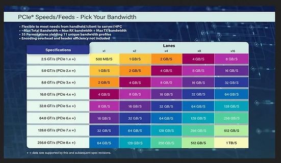
Tabelle der PCIe Bandbreiten nach Generation und Lanes
® Speeds/Feeds - Pick Your Bandwidth • Flexible to meet needs from handheld/client to server/HPC • Max Total Bandwidth = Max RX bandwidth + Max TX bandwidth • 35 Permutations yielding 11 unique bandwidth profiles • Encoding overhead and header efficiency not included Specifications | Lanes x1 | x2 |
in „FCC-Labore auf Gegenseitigkeit, neuer Raspberry Pi-Imager, RISC/V und mehr“ · Mikrocontroller und Digitale Elektronik · · Fotos
-
PDF
IC6963.pdf
Dtyp 2 Dtyp 1 Dtyp 0 Resolution Display i.e. connecting pins DTYP0..2 with VDD- or GND-level 0 0 0 128 x 64 0 0 1 128 x 112 EA 7128-6,8KEL (0: GND, 1: VDD). Please choose our ELECTRONIC ASSEMBLY displays from this table. Displays with 0 1 0 128 x 128 EA P128-7KLED 0 1 1 160 x 128 EA 7160-7KLED other
in „Problem mit IC6963“ · Mikrocontroller und Digitale Elektronik ·
-
PDF
AT90CAN128.pdf
enabled. Figure 12-9. Timer/Counter Timing Diagram, with Prescaler (f clk_I/O) clI/O clTn (cI/O/8) TCNTn MAX - 1 MAX BOTTOM BOTTOM + 1 TOVn 108 AT90CAN32/64/128 7679H–CAN–08/08 AT90CAN32/64/128 Figure 12-10 shows the setting of OCF0A in all modes except CTC mode. Figure 12-10. Timer/Counter Timing Diagram,
in „uC + 3 Schieberegister + 7-Segmentanzeige“ · Mikrocontroller und Digitale Elektronik ·
-
PDF
DSI_Spezifikation_V20_d_.pdf
.................................................. PC-A011, PC-A111 Das EVG begrenzt den Strom auf max. 2mA V 5V I max. 2mA 850us • statische Stromsenke (0Hz) .......................................................................... PCA Excel Das EVG begrenzt den Strom auf max. 2mA V 5V I max. 2mA •
in „DSI Schnittstelle eines Elektronischen Vorschaltgerätes“ · Mikrocontroller und Digitale Elektronik ·
-
PDF
INTERFACE_20.pdf
Baustein Schnittstellenprotokoll am Bus Pins/Gehäuse MAX3160 2Tx/2Rx RS-232 oder 1Tx/1Rx RS-485/RS-422, pin-programmierbar 128 20-SSOP MAX3161 2Tx/2Rx RS-232 oder 1Tx/1Rx RS-485/RS-422, pin-programmierbar 256 24-SSOP MAX3162 2Tx/2Rx RS-232 und 1Tx/1Rx RS-
in „galvanische Trennung RS232“ · Mikrocontroller und Digitale Elektronik ·
-
Datei
ADC128S022.vhd
std_logic_vector(11 downto 0) ) ; end component; component CLKENGEN generic (CNT_MAX: integer:= 16); -- CNT_MAX represents the divider referring to CLK_IN --> (CLK_IN/CNT_MAX)/2 = CLK_OUT port ( -- in ports CLK_IN, RESET: in std_logic; -- out ports CLK_EN: out std_logic ) ; end component; component CLKDIV generic (CNT_MAX: integer:= 8); -- CNT_MAX represents the divider referring to CLK_IN --> (CLK_IN/CNT_MAX)/2 = CLK_OUT port ( -- in ports CLK_IN, RESET: in std_logic; -- out ports CLK_OUT: out std_logic ) ; end component
in „Hilfe bei VHDL-Modul für ADC128S022 im DE0-Nano Board“ · FPGA, VHDL & Co. ·
-
Datei
init_ili9225.h
LCD_SDA 5 #define LCD_CTRL_RS B #define LCD_RS 3 #define LCD_CTRL_CS B #define LCD_CS 4 #define X_MAX_PIXEL 176 #define Y_MAX_PIXEL 220 #define maxxlcd X_MAX_PIXEL #define maxylcd Y_MAX_PIXEL //======================================================================// #define TRANSPARENT 1 #define RED
in „2.2" 176x220 SPI TFT - Kennt jemand dieses Modell?“ · Mikrocontroller und Digitale Elektronik ·
-
PDF
TFH-Board_ONE_-_Sys-Doku_-_V2-3.pdf
IC1 T89C51CC03U-SLSIM 1 PLCC44 74HCT573 IC2 Daten-Latch 1 DIL20 62256 bzw. 681000 IC3 RAM, 32 (bzw.128) kBit * 8 1 DIL28 bzw. DIL32 RTC72421 IC4 Clock-IC 1 DIL18 82C55A IC5 Port-Erweiterung 1 DIL40 XR-88C681SP IC6 DUART 1 DIL28 GAL16V8 IC7 Logik-IC 1 DIL20 MAX807LCP IC8 Watch Dog 1 DIL16 74HCT138 IC9
-
PDF
01051.pdf
downto 0) ); end; Architecture ark_modulering of modulering is signal carrier: integer range -127 to 128; signal data: integer range -127 to 128; signal summa: integer range -127 to 128; signal max_amplitud_data: integer range -127 to 128; signal max_amplitud_carrier: integer range -127 to 128; signal min_amplitud_carrier: integer range -127 to 128; begin process(reset,ModIndex,P_Ut) begin if reset = '1' then max_amplitud_data<=0; max_amplitud_carrier<=0; min_amplitud_carrier<=0; else max_amplitud_data<=ModIndex; max_amplitud_carrier<=(P_Ut-ModIndex
-
Datei
mp3data.c
version, layer and value of bit 15-12 in header. */ const int bitrate_table[2][3][16] = { { {0,32,64,96,128,160,192,224,256,288,320,352,384,416,448,0}, {0,32,48,56, 64,80, 96, 112,128,160,192,224,256,320,384,0}, {0,32,40,48, 56,64, 80, 96, 112,128,160,192,224,256,320,0} }, { {0,32,48,56,64,80,96,112,128,144,160,176,192,224,256,0
in „OT: MP3 durschnittliche variable Bitrate ermitteln“ · Mikrocontroller und Digitale Elektronik ·
