-
PDF
AL2G4-F_Schaltplan.PDF
-rR3r -Ial-ext > Funkmelder AL2G4 2\ i r - ESP8K76-01Interface Magnet-Sensrechts K4(3v3) Hal-rr > MSP-RSf]- I GND < < MSP-TS—l TST S2; Magnet-Senslinks HAL-RL > Debug-lnterface S3 T _ Deckelkontakt -Ial-dk > I . J I ~ i PIR-SensornasonicMN31112J 21 M l-pir > X LIC T1 2x1,5V .fR_ —<FM-EN-VSS| _ Sensorik
in „suche nach geeignetem Optokoppler“ · Mikrocontroller und Digitale Elektronik ·
-
Datei
lcd_c_und_main_c.txt
Taste = 0; P3OUT = 0xF0; // erste Zeile (P3.3) aktiv (low) waitKBD(20); switch (P3IN) { case 0x06: Taste = ('1'); //Zuweisung des entsprechenden ASCII-Werts break; case 0x05: Taste = ('2'); break; case 0x03: Taste = ('3');
in „Fehler in der Switch-Anweisung?“ · Mikrocontroller und Digitale Elektronik ·
-
Datei
0217b-DS10-SD-sektor_auslesen-als_antwort_senden.c
***** // * Datenspeicher 10 * // ******************* // Flüssigkristallanzeige LMK62R125A1 // DS18B20 NR. 13,14,15,16 an 63-10 Adresse 0x18 // E32-868TD Funk ab 29.8.21 //Änderungen: /************************************************************************/ // MSP430F1611 // ----------------- // | XIN
in „512 Byte-Sektor einer SD-Karte mit E32-868T drahtlos übertragen“ · Mikrocontroller und Digitale Elektronik ·
-
Datei
msp430dayII_vr.c
autonomous speech recording // and playback. CPU runs from DCO at the default speed of 1MHz. // // MSP430FG439 // +--------------------+ // | | // | VREF+ +----/\/\/\--- // | | | // | P6.0/OA0I0|----||------+ // | | | // | | MIC // | | | // | | | // | | GND // | | // | ADC0 +-------< input from mic pre-amplifier
in „MSP 430 C-Programm verstehen“ · Mikrocontroller und Digitale Elektronik ·
-
Datei
At45DB161B.c
//****************************************************************************** // MSP430F2274 Interface to AT45DB161B // // Uses Texas Instruments eZ430-RF2500 Development Tool with 16MBit ATMEL Flash // Memory. Wireless connection not used. // //*************************************
in „AT45DB Flash Baustein am MSP430F2274“ · Mikrocontroller und Digitale Elektronik ·
-
Datei
DS10-g0134-PID.c
/* Messstelle 4 = Spannungseingang P6.0 */ //rechts Kanal 4 /* Akku = Spannungseingang P6.1 */ // MSP430F1611 // ----------------- // | XIN|- 32,768kHz // | | | // Taster rot--|RST (58) XOUT|- 32,768kHz //8 MHz X2OUT- | P1.0..P1.7| Daten FKA LMK62 //8 Mhz X2IN- | | // | P3.0| Motorsteuerung A // UTXD0
in „while-Schleife wird "unerlaubt verlassen"“ · Mikrocontroller und Digitale Elektronik ·
-
Datei
DS10-g0120-PID.c
/* Messstelle 4 = Spannungseingang P6.0 */ //rechts Kanal 4 /* Akku = Spannungseingang P6.1 */ // MSP430F1611 // ----------------- // | XIN|- 32,768kHz // | | | // Taster rot--|RST (58) XOUT|- 32,768kHz //8 MHz X2OUT- | P1.0..P1.7| Daten FKA LMK62 //8 Mhz X2IN- | | // | P3.0| Motorsteuerung A // UTXD0
in „while-Schleife vorzeitig verlassen“ · Mikrocontroller und Digitale Elektronik ·
-
Datei
RTC_Sample_03.c
//****************************************************************************** // // MSP430F5418 // ----------------- // /|\ | XIN|- // | | | 32kHz // ---|RST XOUT|- // | | // | P6.1|-->LED // // Built with IAR Embedded Workbench Version: 4.20 //****************************************************************************** #include <msp430x54x.h> extern int SetRTCYEAR(int year); extern int SetRTCMON(int month); extern int SetRTCDAY(int day); extern int SetRTCHOUR(int hour); extern int SetRTCMIN(int min); extern int SetRTCSEC(int sec
in „MSP430 RTC Alarm Interrupt“ · Mikrocontroller und Digitale Elektronik ·
-
Datei
dimmer_code_neu.c
// Dimmer auf Basis des MSP 430 (C) 2006 by T.Hartmann // // der Code darf so oft wie man will kopiert werden solange man sich an die GNU // General Public License Version 2 oder später der Free Software Foundation // hält. //
in „MSP430 F1232 startet nicht“ · Mikrocontroller und Digitale Elektronik ·
-
PDF
DE200610__1_.pdf
ersetzt werden, um die Software direkt in der · Steckdosen mit Kinderschutz Applikation zu debuggen. 75 MSP EZ430-F2013 36. MASTER SLAVE CL6 31. 95 7-fach-Gerätemanager MSP430 F20xx Familie, 16 MHz / MIPS MSP430 F16x Familie · auf der Geräterückseite angeschlossene Geräte Interessanter Baustein, der mit bis
in „ekg schaltung aus heft 10/2006“ · Analoge Elektronik und Schaltungstechnik ·
-
Datei
lcd.txt
// E an P2.2 // DB0-DB7 an P1.0-P1.7 // //--------------------------------------------- #include <msp430x14x.h> // Prototypen void waitLCD(unsigned int i); void LCDOutc(char str); // output eines Zeichens void LCDOuts(char* str); // output eines Strings void LCDInit(void); void LCDClear(void); void
in „Fehler in LCDInit ( ) ???“ · Mikrocontroller und Digitale Elektronik ·
-
PDF
Bauteile.pdf
16 579-MCP125233X50I/MS 1,86 € MCP41100-E/SN Digitalpoti 100kohm 2 579-MCP41100-E/SN 2,08 € B240-13F Diode 40V 2A SMA 2 621-B240-F 0,47 € 25LC640-I/SN EEPROM 64 kbit 9 579-25LC640-I/SN 0,97 € AT24C1024 EEPROM 1MBit 8 A25L80P Flash 8MB 20 L3G4200D Gyro 1 511-L3G4200D B32921C3103M Kondensator 10nF 305VAC
in „[V] diverse Bauteile“ · Markt ·
-
Datei
msp-dmx.c
/************************************/ // msp430-dmx512-recv proto // // Patick Schöberl // // // Clock = 8MHz // // Device = MSP430F149 // /************************************/ #include <signal.h> #include <io.h> void init_uart_dmx(); interrupt
in „DMX schrittmotor steuerung“ · Mikrocontroller und Digitale Elektronik ·
-
Datei
Capture_Input.txt
von 75% ################################################################################ #include "msp430g2553.h" // Headerdatei für MSP430 G2553 einbinden //#include "addon_board.h" // Headerdatei für Erweiterungsplatine unsigned int rising_edge, falling_edge, time_impuls; int durchlauf = 1; void main
in „MSP430 Auslesen einer Impulsdauer mit Capture“ · Mikrocontroller und Digitale Elektronik ·
-
Datei
lcd.txt
// E an P2.2 // DB0-DB7 an P1.0-P1.7 // //--------------------------------------------- #include <msp430x14x.h> /*------PROTOTYPEN----------*/ void waitLCD(unsigned int i); void LCDOutc(char str); // Output eines Zeichens void LCDOuts(char* str); // Output eines Strings void LCDInit(void); // Initialisierung
in „LCD gibt keine ä ö ü aus“ · Mikrocontroller und Digitale Elektronik ·
-
Datei
TIMERTEST_V1.c
von Timer B0 // soll Timer B0 abgeschaltet werden // das soll sich fortlaufend wiederholen #include <MSP430x16x.h> // für MSP430F1610 void STOP_B0 (void); void StartB0 (void); void TimerB0_einstellen(void); void TimerA0_einstellen(void); unsigned char Messwert; unsigned int g; void main(void) { WDTCTL
in „MSP430- TimerA0 soll TimerB0 wiederholt starten“ · Mikrocontroller und Digitale Elektronik ·
-
Datei
B--0193-iar_LP161_E32-868T_konf_und_4x_DS18B20_antworten_b.c
// * E32-868T /DS18B20* // ************************************** // MSP430F1232 // ----------------- // (1) |Test | // (5) |XOUT | // (6) |XIN // E32 M1 |3.0 P1.0| Taster // E32 M0 |3.1 P1.1| n.b. // E32--AUX |3.2 P1.2| Lötauge
in „Sende/Empfangsvorgang mittels nur 1St. µC“ · Mikrocontroller und Digitale Elektronik ·
-
Datei
DS10-g0066b-4xDS18B20_PID.c
***** // * Datenspeicher 10 * // ******************* // Flüssigkristallanzeige LMK62R125A1 // DS18B20 NR. 13,14,15,16 an 63-10 Adresse 0x18 // ************************************************************************* #include <MSP430x16x.h> // für MSP430F1611 #include "DS10-gP12-SD_MAINTI.c" #include
in „Digitaler PID-Regler für elektromotorisches Heizkörperventil“ · Mikrocontroller und Digitale Elektronik ·
-
PDF
heds-1300.pdf
Current Id 1200 50 1000 pA Vd = 5 V, If = 0 1300 50 1000 pA Reflection = 0% Capacitance Cd 1200 100 pF Vd = 0 V, If = 0 1300 100 pF f = 1 MHz Detector Area Ad 1200 0.16 sq-mm Square, with length 1300 0.16 sq-mm = 0.4 mm per side Emitter Electrical/Optical Characteristics @ T = 25 A °C Parameter Symbol
in „Kugelschreiber mit Barcodescanner bei Pollin“ · Mikrocontroller und Digitale Elektronik ·
-
Datei
msp_board_1_main.c
***************************** // Author : Christian Hoefling Date : 04/04/06 // // Target Device : MSP430F2012 // // // Description : Convertion with ADC10, then transmission via SPI interface // // // //********************************************************************************************************************************** #include <msp430x20x2.h> void main(void) { P1DIR |= 0x01; // Set P1.0 to output direction WDTCTL = WDTPW + WDTHOLD; // Stop watchdog timer DCOCTL = DCO2 + DCO1 + DCO0; // DCO = 7 sets frequency of digital controled
in „Problem mit MSP430“ · Mikrocontroller und Digitale Elektronik ·
-
Datei
LCD.txt
#include <msp430.h> #include <stdio.h> #include <stdint.h> void LCD_init(void); void DelayMs(int Ms); void LCD_cmd4(unsigned char cmd); void LCD_dat4(unsigned char byte); unsigned char i; const unsigned char Msg1[] = "LCD Test"; const unsigned char Msg2[] = "MSP430"; void main() { WDTCTL = WDTPW + WDTHOLD // Stop Watchdog Timer P1DIR = 0x0C; // D4 und D5 bestimmen P3DIR = 0x80; // RS bestimmen P4DIR = 0x06; // D6 und D7 bestimmen P8DIR = 0x04; // EN bestimmen
in „MSP430F55 LCD Ansteuerung“ · Mikrocontroller und Digitale Elektronik ·
-
Datei
LCD.txt
#include <msp430.h> #include <stdio.h> #include <stdint.h> void LCD_init(void); void DelayMs(int Ms); void LCD_cmd4(unsigned char cmd); void LCD_dat4(unsigned char byte); unsigned char i; const unsigned char Msg1[] = "LCD Test"; const unsigned char Msg2[] = "MSP430"; void main() { WDTCTL = WDTPW + WDTHOLD // Stop Watchdog Timer P1DIR = 0x0C; // D4 und D5 bestimmen P3DIR = 0x80; // RS bestimmen P4DIR = 0x06; // D6 und D7 bestimmen P8DIR = 0x04; // EN bestimmen
in „LCD Initialisierung W162B-N3LW“ · Mikrocontroller und Digitale Elektronik ·
-
Datei
TS_5435_0118adc12_02.c
#include <msp430.h> #include "msp430x54x.h" #include <TS_5435-LC7981.h> #include <stdio.h> //für sprintf void programmversion(void); long zahl; unsigned int zahla,akku; float g,d,e; char zab[8]; char z1a; int main
in „Bedeutung?: Error: cannot load from …..“ · Mikrocontroller und Digitale Elektronik ·
-
Datei
msp_server.c
#include <msp430.h> #include <stdint.h> #include "msp_server.h" #include "msp_config.h" #include "w5500.h" #include "tags.h" #include "typedefs.h" /////////////////////////////////////////////////////////////// /
in „Send response (Action *Var)“ · Mikrocontroller und Digitale Elektronik ·
-
Datei
msp_server_2.c
#include <msp430.h> #include <stdint.h> #include <string.h> #include "msp_server.h" #include "msp_config.h" #include "w5500.h" #include "tags.h" #include "typedefs.h" /////////////////////////////////////////////
in „Send response (Action *Var)“ · Mikrocontroller und Digitale Elektronik ·
-
Datei
asl_unterstuetzte_prozessoren.txt
Z8F6421 Z8F6422 Z8F6423 Z8F6481 Z8F6482 KCPSM KCPSM3 MICO8_05 MICO8_V3 MICO8_V31 96C141 93C141 90C141 87C00 87C20 87C40 87C70 TLCS-870/C 47C00 470C00 470AC00 97C241 TC9331 16C54 16C55 16C56 16C57 16C64 16C84
in „gas as a68 m68k - was nimmt man ?“ · Mikrocontroller und Digitale Elektronik ·
-
Datei
main.c
************************************************* // I2C-Library // // Stellt I2C-Routinen für den MSP430F149 bereit. SDA // ist an Pin 47 angeschlossen, SCL an Pin 48. Wenn // ihr andere Ports benutzt , müsst ihr nur die // #defines passend ersetzen. //*************************************************** #include "msp430x20x1.h" #define SDA 0x80 //08 #define SCL 0x40 //10 #define MAX6956_BUS_ADDRESS_0 0x40//100 0000 void SCL_low(void); void SCL_high(void); void SCL_clock(void); void SDA_low(void); void SDA_high(void
in „MSP430F2013 I2C Library gesucht“ · Mikrocontroller und Digitale Elektronik ·
-
Datei
Test_247.elf.lst
: f8 23 jnz $-14 ;abs 0x8018 00008028 <__do_clear_bss>: 8028: 3f 40 00 00 mov #0, r15 ;#0x0000 802c: 0f 93 tst r15 802e: 07 24 jz $+16 ;abs 0x803e 8030: 92 42 00 11 mov &0x1100,&0x0120 8034: 20 01 8036:
in „MSPGCC: Interruptvetortablle fehlt“ · Mikrocontroller und Digitale Elektronik ·
-
Datei
msp_server_1.c
#include <msp430.h> #include <stdint.h> #include <string.h> #include <stdlib.h> #include "msp_server.h" #include "msp_config.h" #include "w5500.h" #include "tags.h" #include "typedefs.h" /////////////////////////
in „Send response (Action *Var)“ · Mikrocontroller und Digitale Elektronik ·
-
Datei
lcd_test2.c
#include "msp430x20x3.h" //*** MSP430F2013 mit integriertem RC-Oszillator #define delay_1us() for (_counter1_Delay=0; _counter1_Delay<2; _counter1_Delay++); //*** 9us #define delay_5us() for (_counter1_Delay=0; _
in „ez430 msp340f2013 eclipse mspgcc“ · Mikrocontroller und Digitale Elektronik ·
-
Datei
main.c
#include "msp430x20x3.h" //*** MSP430F2013 mit integriertem RC-Oszillator #define delay_1us() for (_counter1_Delay=0; _counter1_Delay<1; _counter1_Delay++); //*** 9us #define delay_5us() for (_counter1_Delay=0; _
in „LCD an EZ430 mit MSPGCC und CCE3“ · Mikrocontroller und Digitale Elektronik ·
-
Datei
TS-iP59_V19_FKA_240160A.c
// Flüssigkristallanzeige graph. FKA DEM240160A // Ansteuerungs-IS: UC1968u, Schnittstelle 8080 // MSP430F1611 // ----------------- // | XIN|- 32,768kHz // | | // Taster rot--|RST (58) XOUT|- 32,768kHz // 8 Mhz X2IN- | P2.1|Taster // | P2.0|Taster // 8 MHz X2OUT- | P1.0..P1.7|Daten FKA // | | // | P3.0
in „Display DEM240160A mit UC1698u einzelne Bildpunkte setzen“ · Mikrocontroller und Digitale Elektronik ·
-
Datei
TS-iP59_V27_FKA_240160A._gek.c
// Flüssigkristallanzeige graph. FKA DEM240160A // Ansteuerungs-IS: UC1968u, Schnittstelle 8080 // MSP430F1611 // ----------------- // | XIN|- 32,768kHz // | | // Taster rot--|RST (58) XOUT|- 32,768kHz // 8 Mhz X2IN- | P2.1|Taster // | P2.0|Taster // 8 MHz X2OUT- | P1.0..P1.7|Daten FKA // | | // | P3.0
in „LCD DEM240160 mit UC1698 wie Bildspeicher auslesen“ · Mikrocontroller und Digitale Elektronik ·
-
Datei
funktionen.c
**************************** // // Funktionen-Library // // Stellt verschiedene Funktionen für den MSP430-F2013 zur verfügung // // Last update: 20.03.2010 by Mojo // // Original writen by Mojo // //****************************************************************************** #include "funktionen.h" #include "io430.h" // Millisekunden warten void WaitMs(unsigned int time){ unsigned int i,j; time=time*MHERZ; for(i=0;i<time;i++)for(j=0;j<161;j++); } // Mikrosekunden warten (den gewünschten Wert durch 6,2 Teilen)
in „LCD versagt beim anschließen der BackLight“ · Mikrocontroller und Digitale Elektronik ·
-
Datei
main.c
// #include "msp430f5529.h" // Einbinden der Definitionen #include <msp430.h> #define T_OnOff 0x02 // Taster an P1.1 #define T_SET 0x02 // Taster an P2.1 #define LED_ON 0x80 // LED (grün) an P4.7 #define LED_X 0x01
in „MSP430 F5529 Wobbel-Generator“ · Mikrocontroller und Digitale Elektronik ·
-
PDF
Schematic_Bresser_5in1_I2C_2022-10-31.pdf
1 2 3 4 5 +3.3V +3.3V HDR-M-2.54_1x6 RAIN R7 +3.3V +3.3V HDR-F-2.54_1x2 20K PMV48XP 10 1 Q1 IR_LED 2 1 RAIN_PULSE C4 SBWTCK 3 A 2 20K 4.7uF SBWTDIO 4 A +3.3V 5 GND 6 +3.3V GND GND HDR-F-2.54_1x15 R2 20K R6 U2 GND 15 WIND_PULSE 20 +3.3V MSP430F2013IPWR +3.3V 14 1
in „Bresser 5in1 umbau auf eigene Platine“ · Mikrocontroller und Digitale Elektronik ·
-
 Bild
Screenshot eines Terminal-Programms mit seriellen Daten
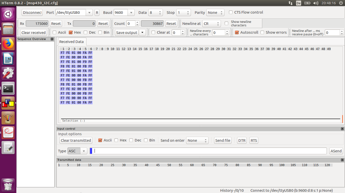
after ... ms receive pause (0=off) 0 Received Data 1 2 3 4 5 6 7 8 9 10 11 12 13 14 15 16 17 18 19 20 21 22 23 24 25 26 27 28 29 30 31 32 33 34 35 36 37 38 39 40 41 42 43 44 45 46 47 48 49 F7 FE 01 00 FA FF F7 FE 00 00 FA FF F7 FE 01 00 F9 FF F7 FE 01 00 FB FF F7 FE 00 00 FA FF F7 FE 00 00 FB FF F7 FE 02 00 FB FF F7 FE 00 00 FB FF F7 FE 00 00 FA FF F7 FE 01 00 FF Input control Input options ASCII Hex Dec Bin Send on enter None Send file DTR RTS Type ASC Transmitted data 1 5 10 15 20 25 30 35 40 45 50 55 60 65 70
in „MSP430G2553, I2C read falsche Reihenfolge bei der Ausgabe“ · Mikrocontroller und Digitale Elektronik · · Screenshots
-
Datei
C-200a.c
Testschaltung 1611* // ******************** // graph. Flüssigkristallanzeige FKA LC7981 // Uhr DS32C35 // MSP430F1611 // ----------------- // | XIN|- 32,768kHz // | | // Taster rot--|RST (58) XOUT|- 32,768kHz // P5.7|LED rot // | P5.6|LED Grün // 8 Mhz X2IN- | P2.1|Taster // | P2.0|Taster // 8 MHz X2OUT- |
in „Sende/Empfangsvorgang mittels nur 1St. µC“ · Mikrocontroller und Digitale Elektronik ·
-
Datei
DS_5_GPS_V09-NMEA.c
1xBatteriespannung // Programm 6: 1x ADW Versuch 1 Werte à 16 BIT ADS8345 // Programm 7: GPS auf SM-Karte // // MSP430F1611 // ----------------- // /|\| XIN|- 32,768kHz // | | | // Taster rot--|RST (58) XOUT|- 32,768kHz // | P1.7|LED Grün // 8 Mhz X2IN- | P1.6|Taster für löschen // | P1.5|Taster für Start //8 MHz
in „MSP430F149 NMEA String mit UART1 empfangen und auswerten“ · Mikrocontroller und Digitale Elektronik ·
-
PDF
catalog-3.pdf
]: 9.1224 USD [QTY]: 1 [Category]: Microcontrollers [Desc]: MCU 32-bit STM32F ARM Cortex M3 RISC 128KB Flash 2.5V/3.3V 64-Pin LQFP Tray MPN: MSP430F169IPM [ID]: 000170 [Price]: 18.479 USD [QTY]: 4 [Category]: Microcontrollers [Desc]: MCU 16-bit MSP430 MSP430 RISC 60KB Flash 3.3V 64-Pin LQFP Tray MPN: MSP430F1491IPMR [ID]: 000171 [Price]: 11.837 USD [QTY]: 3 [Category]: Microcontrollers [Desc]: 8 MHz MCU with 60KB Flash, 2KB SRAM, 12-bit ADC, comparator, SPI/UART 64-LQFP -40 to 85 MPN: ATMEGA324PV-10AU
-
PDF
catalog.pdf
Desc]: MCU 32-bit STM32F ARM Cortex M3 RISC 128KB Flash 2.5V/3.3V 64-Pin LQFP Tray MPN: MSP430F169IPM [ID]: 000170 [Price]: 13.41 USD [QTY]: 4 [Category]: Microcontrollers [Desc]: MCU 16-bit MSP430 MSP430 RISC 60KB Flash 3.3V 64-Pin LQFP Tray MPN: MSP430F1491IPMR [ID]: 000171 [Price]: 8.59 USD [QTY]: 3 [Category]: Microcontrollers [Desc]: 8 MHz MCU with 60KB Flash, 2KB SRAM, 12-bit ADC, comparator, SPI/UART 64-LQFP -40 to 85 MPN: ATMEGA324PV-10AU
-
PDF
catalog.pdf
: 6.62 USD [QTY]: 1 [Category]: Microcontrollers [Desc]: MCU 32-bit STM32F ARM Cortex M3 RISC 128KB Flash 2.5V/3.3V 64-Pin LQFP Tray MPN: MSP430F169IPM [ID]: 000170 [Price]: 13.41 USD [QTY]: 4 [Category]: Microcontrollers [Desc]: MCU 16-bit MSP430 MSP430 RISC 60KB Flash 3.3V 64-Pin LQFP Tray MPN: MSP430F1491IPMR [ID]: 000171 [Price]: 8.59 USD [QTY]: 3 [Category]: Microcontrollers [Desc]: 8 MHz MCU with 60KB Flash, 2KB SRAM, 12-bit ADC, comparator, SPI/UART 64-LQFP -40 to 85 MPN: ATMEGA324PV-10AU
-
PDF
AL2G4_SCH.PDF
3 R3 R4 K 2 2 1 2 1 1 2,2K 2 2,2K V MINIATUR-PRINT-TASTER_20MM 6 1 3 5 D S4 + F 7 1 µ 1 Vcc P2.3 11 2 1 C , P1.0 P2.4 1 2 2 2 12 7 2 3 P1.1 P2.5 13 4 R K4 3v3 4 P1.2 P1.6 14 R5 4,7K 2 1 5 P1.3 P1.7 15 2 Gnd SMD-REEDSENSOR-P3S_AW10-15 P1.4 RST~ Rst 6 16 1 2 3 Test 7 P1.5 Test 17 2 4 8 P2.0 P2.7 18 1 1 n 1 2 9 P2.1 P2.6 19 C 1 1 2 10 P2.2 Vss 20 S1 S2 MSP430G2553IN20 K5 SMD-REEDSENSOR-P3S_AW10-15 TxD 1 2 8266Interface K7 1 2 3 4 K6 RxD 5 6 1 2 7 8 3 8 1 1 K T T IC2 D 1 2 3 4 5 6 L L 2 2 S 2 5 2 5 2 0 0 F + 4 F 6 R R µ0 1 C 0 n 1 C 3 4 1 B 5
in „Ein weiteres mal das Thema NIMH mit Solarpanel laden“ · Analoge Elektronik und Schaltungstechnik ·
-
PDF
SEN-FB-G-Material.pdf
.2022 16:28 ; Variante=AllVars ; Platine=<alle Bauteile> ; Autor= ; Pos Name Wert Gehäuse 1 C1 100µF 1210 2 C2 100µF 1210 3 C3 100µF 1210 4 C5 1nF 0805 5 D1 L-934-5V_3MM L_ROTMM_ROT 6 D2 LTE-5208A LED_5mm_INFRAROT_liegend 7 K1 BatteriehaltefArTEAIZelLTERUNG AAA 8 K2 BatteriehaltefArTEAIZelLTERUNG AAA
-
Datei
main.c
DigiPins bauen * *****************************************************************************/ #include "msp430x20x3.h" #include "signal.h" #define counter 0x1f short m_SD16 = 0; // membervariable des SD16 fuer alle berechnungen short m_VarArray[counter]; char i = 0; long temp = 0; short X1,X2,Y1,Y2 = 0; /
in „MSP430 can't allocate stack“ · Mikrocontroller und Digitale Elektronik ·
-
PDF
Schematic_Prints.pdf
CS (P48)12 CSB 10µF 10V SCLK_DISPLAY (P48)13 B MOSI_DISPLAY (P1) 14 SCL B GND 3.3V 15 MOSI 16 VDDIO VDD 17 VSS C22 VDD_18V 18 VDD_18V C21 1µF 50V VOTP 19 VOTP 1µF 50V C20 VSH 20 1µF 50V VGH 21 VSH IC1 C18 VSHR 22 VGH 1µF
in „[S] Bestückung von Adapterplatinen für elektronische Preisschilder“ · Markt ·
-
PDF
Schematic_Prints.pdf
MBR0503 CS (P48)12 CSB 10µF 10V SCLK_DISPLAY (P48)13 B MOSI_DISPLAY (P1) 14 SCL B GND 3.3V 15 MOSI 16 VDDIO VDD 17 VSS C22 VDD_18V 18 VDD_18V C21 1µF 50V VOTP 19 VOTP 1µF 50V C20 VSH 20 1µF 50V VGH 21 VSH IC1 C18 VSHR 22 VGH 1µF
in „[S] Bestückung von Adapterplatinen für elektronische Preisschilder“ · Markt ·
-
PDF
Komfortblinker.pdf
17 TCK SW_L J1-4 TEST 1 NMI/RST P1.4/SMCLK/TCK 18 TMS , , , , R6 8,2k C1 6 TEST P1.5/TA0/TMS 19 TDI F F F F 5 XIN P1.6/TA1/TDI/TCL20 TDO Z Z Z Z 10n X1 XOUT P1.7/TA2/TDO/TDI 3 k 4 k 5 k 6 k 1 2 P2.0/ACLK/A08 D 2 , D 3 , D 4 , D 5 , 4 3 P2.1/INCLK/A19 R 3 R 3 R 3 R 3 V P2.2/TA0/A210 1 32,768kHz P2.3/TA1/A3/VREF-/VEREF-1 + P2.4/TA2/A4/VREF+/VEREF+12 P2.5/ROSC 3 GNDGND GNDGND GNDGND GNDGND 3 MSP430F1122DW OUT_R K1 GND 5 35701331 V 1 Q2 + BC847SMD 3 1k K2 35701331 R11 5 Q1 BC847SMD 1k GND OUT_L R10 GND
in „Eingangsbeschaltung Atmega im Kfz (nicht die üblichen Fragen!)“ · Mikrocontroller und Digitale Elektronik ·
-
PDF
AMIS-30543-D.pdf
(Note 12) 100 −20 +80% mF C 2 C3 VBB Decoupling Block Capacitor 100 −20 +80% nF (Note 13) C4 VDD Buffer Capacitor 100 $20% nF C5 VDD Buffer Capacitor 100 $20% nF C6 Charge Pump Buffer Capacitor 220 $20% nF C7 Charge Pump Pumping Capacitor 220 $20% nF C8 Low Pass Filter SLA 1 $20% nF R1 Low Pass Filter SLA 5.6 $1% kW R2, 3, 4 Pullup Resistor Open Drain Output 4.7 $1% kW D1 Optional Reverse Protection Diode MURD530 12.ESR < 1 W. 13.ESR < 50 mW.
in „Puls aus Sinuswelle herausrechnen“ · Mikrocontroller und Digitale Elektronik ·
-
PDF
teileliste.pdf
Nummer Menge Name Preis/Stück Bemerkung kurz Bild 1 50 100kOhm Kohleschicht 0,02 € nur als Zugabe 2 20 100nF Vielschicht 0,02 € nur als Zugabe - 3 30 10kOhm Kohleschicht 0,02 € nur als Zugabe - 4 40 110Ohm Metallschicht 1% 0,02 € nur als Zugabe - 5 30 1kOhm Metallschicht 1& 0,02 € nur als Zugabe - 6 50
in „[V] Aufräumaktion“ · Markt ·