-
Datei
main.asm
******************************************************************************** Funktion: ATtiny13a (4.8MHz) empfängt ROM und ROM Daten von DS18B20 oder DS18S20 im 5 Sekunden-Takt. Die Daten werden umgerechnet und per I2C über PCF8574 zum LCD1602/2004 übertraben. Line1: Anzeige DS18B20 oder DS18S20
in „AVR ATtiny13 DS18B20/DS18S20 I2C PCF8574 LCD Temperaturanzeige“ · Projekte & Code ·
-
Datei
MSP3400_ATMEGA32_ADC_2.ino
2 #define KEY3_PIN PD5 // Fronttaste 3 bool minusWasActive = false; #define MSP_ADDR 0x40 #define PCF_ADDR 0x20 #define PCF_STEREO 0x30 #define PCF_SONORAMA 0xA0 #define PCF_PSEUDO 0x90 #define PCF_SPATIAL 0xF0 // --- Funktionsprototypen --- void MSP_SetVolumeBoth(uint16_t vol); void applySoundProfile
in „Zeigt her eure Kunstwerke (ab 2023)“ · Projekte & Code ·
-
Datei
MSP3400_ATMEGA32_ADC_2.ino
2 #define KEY3_PIN PD5 // Fronttaste 3 bool minusWasActive = false; #define MSP_ADDR 0x40 #define PCF_ADDR 0x20 #define PCF_STEREO 0x30 #define PCF_SONORAMA 0xA0 #define PCF_PSEUDO 0x90 #define PCF_SPATIAL 0xF0 // --- Funktionsprototypen --- void MSP_SetVolumeBoth(uint16_t vol); void applySoundProfile
in „AUDIOCONTROLLER MSP3400C einfach mit ATMEGA32 ansteuern“ · Projekte & Code ·
-
PDF
PCA8574-rev02.pdf
a read is selected, while a logic 0 selects a write operation. When AD2, AD1 and AD0 are held to V DD or VSS, the same address as the PCF8574 or PCF8574A is applied. 7.1.1 Address maps Table 4. PCA8574 address map A6 A5 A4 A3 A2 A1 A0 Address 0 1 0 0 0 0 0 20h 0 1 0 0 0 0 1 21h 0 1 0 0 0 1 0 22h 0 1 0 0 0 1 1 23h 0 1 0 0 1 0 0 24h 0 1 0 0 1 0 1 25h 0 1 0 0 1 1 0 26h 0 1 0 0 1 1 1 27h PCA8574_PCA8574A_2 © NXP B.V
in „NXP PCA8574 hat Phänomen mit 2 Adressen“ · Mikrocontroller und Digitale Elektronik ·
-
PDF
BFE_AG_Di_230_Dot_Matrix.pdf
1 2 3 4 5 6 7 8 5V 5V IC3 PCF8574 IC5C P0 PIIC501 PIIC5016 I4 IC8A8B P1 PIIC502A VCC PIIC802 PR PIIC805N74AHC74D A P2 3 B 15 D Q o o o o o o o o o o A P3 PIIC503C Y0 PI145015 3 P4 PIIC506 Y1 PIIC5013 PIIC803CLK P5 4 OE1 Y2 12 6
in „[V] #VERKAUFT# Platine mit 8 Stück DLG7137, 5*7 Punktmatrix“ · Markt ·
-
PDF
BFE_AG_Di_230_Dot_Matrix.pdf
1 2 3 4 5 6 7 8 5V 5V IC3 PCF8574 IC5C P0 PIIC501 PIIC5016 I4 IC8A8B P1 PIIC502A VCC PIIC802 PR PIIC805N74AHC74D A P2 3 B 15 D Q o o o o o o o o o o A P3 PIIC503C Y0 PI145015 3 P4 PIIC506 Y1 PIIC5013 PIIC803CLK P5 4 OE1 Y2 12 6
-
Datei
PIC_41__2-06_.asm
; Programm LCDEXP0.asm: Demoprogramm für LCD-Modul, angesteuert über Expander PCF8574 ; PIC 16F84, f = 4 MHz, SC = 1us; OUT(sda) an RA0, CLOCK(scl) an RA1, CS an RA2 ; Dieter Kohtz, Juni 2005 ;***************************************************************************************
in „LCD am I2C initialisieren“ · Mikrocontroller und Digitale Elektronik ·
-
Datei
mcp23017_2.c
MCP23S17_I2C_Write(IODIRB, 0x00); */ void MCP23017_I2C_Ausgabe_2 (void) { MCP23017_I2C_write (GPIOA, wort_a); MCP23017_I2C_write (GPIOB, wort_a); #ifdef UART_debug_23017 uart_puts( "\n\r" ); // neue Zeile und Rücklauf uart_puts( "lies GPIOB: " ); // MCP23017_I2C_read (GPIOB); //bleibt hängen in "pcf8574_send_start" beim Warten auf das TWINT-Bit; 0 1 1 1 A2 A1 A0 RW ACK PCF8574P-Adresse // uart_puti((uint16_t) MCP23017_I2C_read (GPIOA)); uart_puti( MCP23017_I2C_read (GPIOB)); // liest 50 // uart_puti( MCP23017_I2C_read (IOCONA)); // liest 40 = 0x28, was
in „I2C - Pull Up Widerstände“ · Mikrocontroller und Digitale Elektronik ·
-
PDF
lalus.pdf
MFV-Gebers. DTMF- zeigt die Organisation des spre- Geber II 010. II VO- 8 II * Expander * Schalter y (PCF 8574) Postleitung ii ELECTRONIC ACTUELL Magazin 8/97 3 frage geht, dann meldet er das artig Die Blockschaltung Triggersign8\ retriggerbares vom Prozessor mit ,,Temperatur”, gefolgt von den Auf der Grafik
in „Schaltung an a/b - Port (Telefonanlage) anbinden“ · Mikrocontroller und Digitale Elektronik ·
-
Datei
i2c.h
/////////////////////////////////////////////////////////////////////////////////////////////// // PCF8574 (Remote 8-bit I/O expander) /////////////////////////////////////////////////////////////////////////////////////////////////// #define I2C_ADDR_PCF8574 0x20 // 00100AAA #define CHANNEL_1 0x01 #
in „MSP430F2370 I2C“ · Mikrocontroller und Digitale Elektronik ·
-
Datei
i2c.h
/////////////////////////////////////////////////////////////////////////////////////////////// // PCF8574 (Remote 8-bit I/O expander) /////////////////////////////////////////////////////////////////////////////////////////////////// #define I2C_ADDR_PCF8574 0x20 // 00100AAA #define CHANNEL_1 0x01 #
in „I2C Ansteuerung von PCA9685 mit MSP430“ · Mikrocontroller und Digitale Elektronik ·
-
Datei
CAN_MCP2515-test2.bas
pins Spiinit '--------------------------Für I2C LCD ----------------------------------------- Const Pcf8574_lcd = 112 'PCF Adresse für LCD (original Pcf8574_lcd =70) $lib "Lcd_i2c.lib" 'I2C Treiber für das LCD Dim _lcd_e As Byte 'Um auch LCDs mit 2 Controllern 'nutzen zu können. _lcd_e = 128 'Für LCDs
in „MCP2515 mit BASCOM“ · Mikrocontroller und Digitale Elektronik ·
-
PDF
notes_82b96.pdf
peripheral chip that has been uniquely selected. Sub-addressing by means of port expander chips like PCF8574 has been widely used in telephone exchange systems. In this case the A0/A1/A2 pins of other I2C chips are modified by first writing one data word into several PCF8574s which shared one common I2C
in „18 x SHT11 an welchem Mikrocontroller“ · Mikrocontroller und Digitale Elektronik ·
-
PDF
notes_82b96.pdf
peripheral chip that has been uniquely selected. Sub-addressing by means of port expander chips like PCF8574 has been widely used in telephone exchange systems. In this case the A0/A1/A2 pins of other I2C chips are modified by first writing one data word into several PCF8574s which shared one common I2C
in „I²C galvanisch trennen“ · Mikrocontroller und Digitale Elektronik ·
-
Datei
prog.c
Registers definitions #include <io.h> #include <delay.h> #include <stdio.h> #include <twix.h> #define PCF8574_ADDR 0x38 unsigned char pcf_value_a=0x55; unsigned char pcf_value_b=0xAA; // System Clocks initialization void system_clocks_init(void) { unsigned char n,s; // Optimize for speed #pragma optsize
in „Codevision CodeWizardAVR TWI Probleme“ · Mikrocontroller und Digitale Elektronik ·
-
PDF
Ausgangsstufen_Logic_IC.pdf
aufgenommen werden. Bei HIGH können nur sehr geringe Ströme entnommen werden, siehe Port-Expander PCF8574. Der Widerstandswertes des Pull-up-Widerstands darf nicht zu groß gewählt werden, da sonst zusammen mit Eingangs- und parasitären Kapazitäten die Signale verschleifen und im Extremfall nicht mehr
in „Wittig(welec) DSO W20xxA Open Source Firmware (Teil3)“ · Mikrocontroller und Digitale Elektronik ·
-
Datei
LCD_I2C_01.asm
HD44780 compatible ; P7 P6 P5 P4 P3 P2 P1 P0 ; D7 D6 D5 D4 LED ENA R|W RS ; Device slave address: $38 (PCF8574A) ;ATtiny2313 memory use summary [bytes]: ;Segment Begin End Code Data Used Size Use% ;[.cseg] 0x000000 0x000318 722 70 792 2048 38.7% ;[.dseg] 0x000060 0x000060 0 0 0 128 0.0% ;[.eseg] 0x000000
in „I2C Display einfache Frage“ · Mikrocontroller und Digitale Elektronik ·
-
Datei
LCD_Init_USI.asm
LCD power on self reset rcall twistart ldi temp, 0x7E ; slave start adresse + RW-Bit rcall twiout ; PCF8574->0x40..4E; PCF8574A->0x70..7E rcall lcd_eight_bit ; LCD-Init: eight bit rcall lcd_eight_four ; LCD-Init: eight to four bit change rcall lcd_four_two_r ; LCD-Init: four bit, 2 rows rcall lcd_on_off
in „AVR-Tutorial: LCD - Erweiterung lcd-routines.asm - Bitte um Feedback“ · Mikrocontroller und Digitale Elektronik ·
-
Datei
LCD_Ausgabe_TWI_USI.asm
LCD Self-Reset abwarten rcall twistart ldi temp, 0x70 ; Slave Startadresse + RW-Bit rcall twiout ; PCF8574->0x40; PCF8574A->0x70 rcall lcd_achtbitinit ; LCD-Init: acht Bit rcall lcd_acht_vier ; LCD-Init: acht zu vier Bit rcall lcd_vier_zwei_z ; LCD-Init: vier Bit, 2 Zeilen rcall lcd_on_off ; LCD-Init
in „RE Bit Display EA DIP204-4 (KS0073)“ · Mikrocontroller und Digitale Elektronik ·
-
Datei
T6963c.h
0x03 #define T6963C_TEXT 0x04 #define T6963C_GRAPHIC 0x08 #define T6963C_TEXT_GRAPHIC 0x0C void writePCF8574A(uint8_t cmd, unsigned char data); unsigned char readPCF8574A_DATA(); //Sets Port & Initializes T6963c void T6963cInit(uint8_t Options, uint8_t Mode); //Set Cursor-Pattern void T6963cCursorPattern
in „Frage zu SPI und MCP23S09“ · Mikrocontroller und Digitale Elektronik ·
-
PDF
I2C-Platine-LCD_von_Pollin.pdf
Anschlussklemme 2-polig 3 JP1, JP2, JP3Stiftleiste 1x3-polig mit Bestückungsplan Codierbrücken 1 Q1 BC327 1 IC1 PCF8574P 1 Platine Stückliste 2 Widerstände: Um mit der Montage derWiderstände beginnen zu können, muss zunächst ermittelt werden, welchenWert jeder einzelne Widerstand besitzt, um ihn so anschließend an
in „I2C und LCD mit der Pollin.Lib in Bascom“ · Mikrocontroller und Digitale Elektronik ·
-
Datei
SainSmart_USI_27022026.asm
HD44780 compatible ; P7 P6 P5 P4 P3 P2 P1 P0 ; D7 D6 D5 D4 LED ENA R|W RS ; Device slave address: $38 (PCF8574A) ;ATtiny4313 memory use summary [bytes]: ;Segment Begin End Code Data Used Size Use% ;[.cseg] 0x000000 0x00031c 726 70 796 4096 19.4% ;[.dseg] 0x000060 0x000060 0 0 0 256 0.0% ;[.eseg] 0x000000
in „HD44780 I2C Adapter“ · Mikrocontroller und Digitale Elektronik ·
-
Datei
test_atmega8535_I2C_LCD_switches.asm
HD44780 compatible ; P7 P6 P5 P4 P3 P2 P1 P0 ; D7 D6 D5 D4 LED ENA R|W RS ; Device slave address: $38 (PCF8574A) 0x70/0x40 ; ATmega8535 memory use summary [bytes]: ; Segment Begin End Code Data Used Size Use% ;[.cseg] 0x000000 0x000346 732 106 838 8192 10.2% ;[.dseg] 0x000060 0x000060 0 0 0 512 0.0% ;[.eseg
in „ATMega 48, Pinchange Interrupt, ASM“ · Mikrocontroller und Digitale Elektronik ·
-
PDF
BFE-Di_230_schematic.pdf
2 C(a) C(h) 15 120 BC847 2 R 1 A(a) A(h) 3 A(b) A(g) 14 R10 4 13 R14 D3 R29 120 C(b) C(g) 120 4148 100k 120 5 C(c) C(f) 12 120 U9B GND 6 11 74HC11 R11 7 A(c) A(f) 10 R15 BAR_FF_~{RST} R12 A(d) A(e) R16 3 Q5
-
PDF
BFE-Di_230_schematic.pdf
2 C(a) C(h) 15 120 BC847 2 R 1 A(a) A(h) 3 A(b) A(g) 14 R10 4 13 R14 D3 R29 120 C(b) C(g) 120 4148 100k 120 5 C(c) C(f) 12 120 U9B GND 6 11 74HC11 R11 7 A(c) A(f) 10 R15 BAR_FF_~{RST} R12 A(d) A(e) R16 3 Q5
-
PDF
84123_usb_i2c_km-2.pdf
Aktivität auf SDA-Leitung: Bit 7 Bit 6 Bit 5 Bit 4 Bit 3 Bit 2 Bit 1 Bit 0 vom Master vom Slave 1 0 0 1 A0 A1 A2 1/0 Beispiel: 7-Bit-Adresse und R/W-Bit von Temperatursensor LM75 und A/D-D/A-Konverter PCF8591 Übertragungsbeispiele 7-Bit-Adressierung: Master sendet an Slave SLAVE-ADRESSE Write START 1001000
in „Hygrosens I2C Tmp Modul antwortet nicht“ · Mikrocontroller und Digitale Elektronik ·
-
PDF
Readme_130816.pdf
der als TWI-Master / TWI-Slave arbeitet - Die Stromaufnahme des ATMega beträgt im Idle-Modus unter 1mA. Vom PC aus kann mit beliebiger Software, die via Serieller Schnittstelle senden und empfangen kann (z.B. mit Python - oder im einfachsten Fall mit Hilfe eines Terminal- programms) mit dem "Rasp"-Mega
-
 Bild
Bild
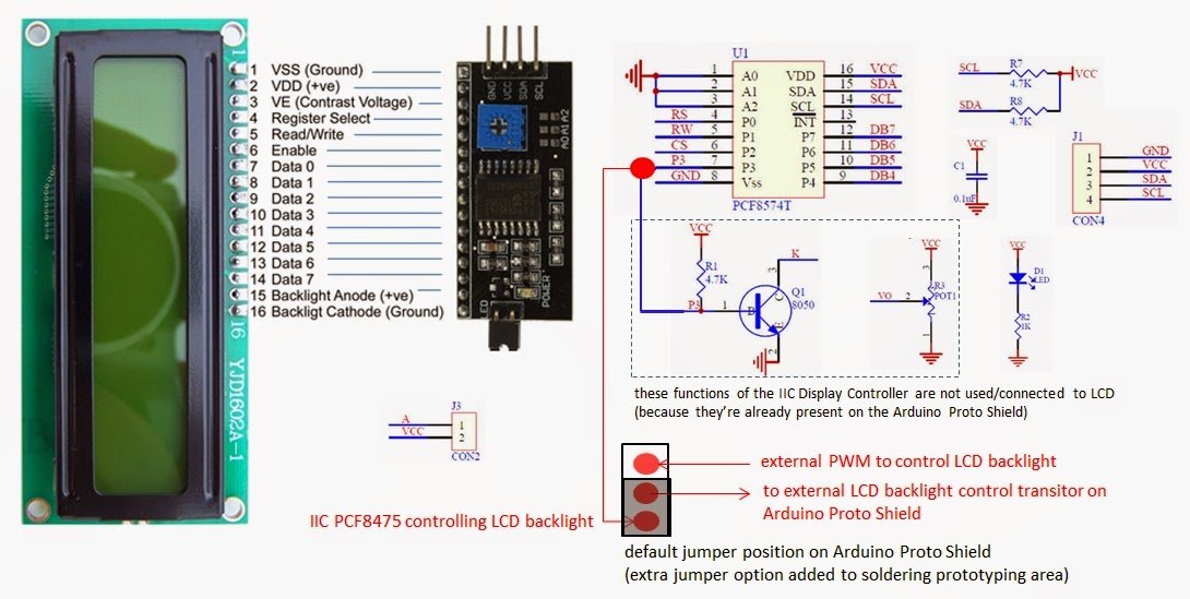
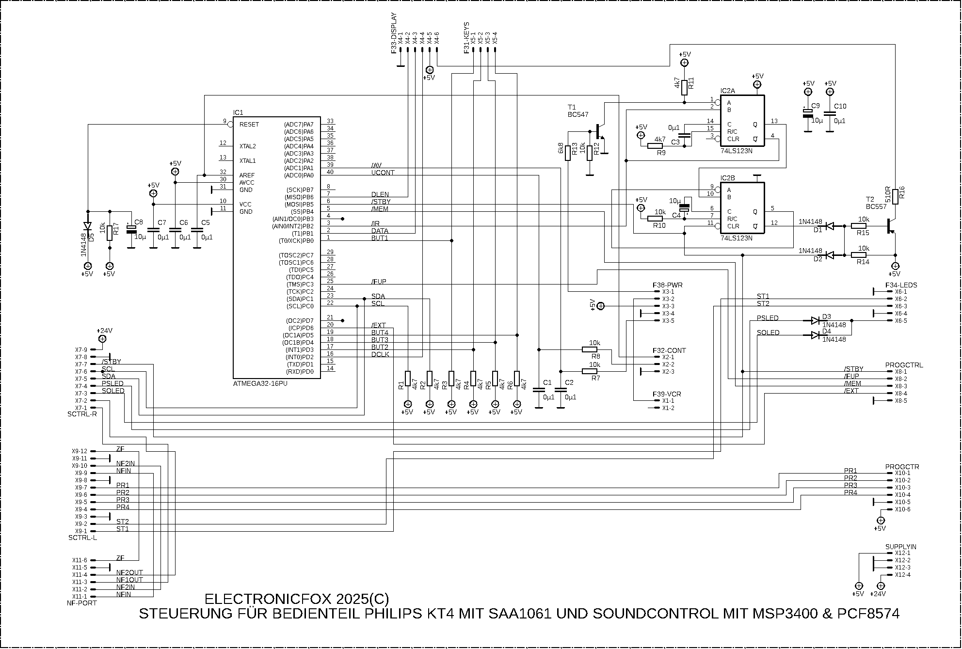
LCD-Display, PCF8574T I2C-Adapter und Schaltplan
Data 4 12 Data 5 13 Data 6 14 Data 7 15 Backlight Anode (+ve) 16 Backlight Cathode (Ground) YJD1602A-1 U1 16 VCC 15 SDA 14 SCL 13 DB7 12 DB6 11 DB5 10 DB4 9 P4 8 P3 7 GND 6 VSS 5 P5 4 P0 3 CS 2 RW 1 RS A0 A1 A2 SCL SDA VCC R7 4.7K SDA R8 4.7K VCC J1 1 GND 2 VCC 3 SDA 4 SCL CON4 C1 0.1uF PCF8574T VCC
in „PCF8574 I2c Adapter mit ASM ansteuern“ · Mikrocontroller und Digitale Elektronik · · Fotos
-
Datei
Atmega8535_05102026.asm
HD44780 compatible ; P7 P6 P5 P4 P3 P2 P1 P0 ; D7 D6 D5 D4 LED ENA R|W RS ; Device slave address: $38 (PCF8574A) 0x70 ; ATmega8535 memory use summary [bytes]: ; Segment Begin End Code Data Used Size Use% ;[.cseg] 0x000000 0x000362 760 106 866 8192 10.6% ;[.dseg] 0x000060 0x000060 0 0 0 512 0.0% ;[.eseg]
in „ATMega 48, Pinchange Interrupt, ASM“ · Mikrocontroller und Digitale Elektronik ·
-
PDF
Schrittmotor.pdf
verzichten. Der I2C – Bus erfüllt hier die Anforderungen an die Steuerung. Als Hardware benötigt man einen PCF8574 (I/O – Expander) und einen Motortreiber, z.B. den ULN2803A, der oben bereits beschrieben ist. Da die I2C – Routinen bereits im Lallusprogramm implementiert sind, bläht sich der Programmcode auch
in „schrittmotor Steuerung“ · Platinen ·
-
PDF
PA100D.pdf
MENU DISP R15 13 4 Q7 GND /INT_KBD INT P0 5 BC856ASMD 15 SDA P2 6 14 SCL P3 7 LED2_GN 3k3 P4 9 R12 1 A0 P5 10 150 2 A1 P6 11 3 A2 P7 12 T T T T T R16 D 1 2 D 1 2 D 1 2 D 1 2 D 1 2 C VSS 8 S S S S S C C 3 4 3 4 3 4 3 4 3 4 C V PCF8574T GND GND STBY/OPER GND 22-27-2021-02 IC13 X1-2 7 6 VDD 16 C17 4 R ATT
in „Schutzbeschaltung Analog-Eingänge / Durchsicht Schaltplan“ · Mikrocontroller und Digitale Elektronik ·
-
Datei
i2clcd.c
**************** i2clcd.c - LCD over I2C library Designed for HD44870 based LCDs with I2C expander PCF8574X on Atmels AVR MCUs Copyright (C) 2006 Nico Eichelmann and Thomas Eichelmann 2014 clean up by Falk Brunner This library is free software; you can redistribute it and/or modify it under the terms
in „Tastenentprellung seltsames Phänomen“ · Mikrocontroller und Digitale Elektronik ·
-
Datei
Neu_Textdokument.txt
************************ ;**** TWI TEST **** ;********PCF8547A******** ;************************ .include "m8def.inc" .def temp =r16 .equ SLA_W =0x70 ;adresse pcf8574a a0&a1&a2=low .equ start =0x08 .equ MT_SLA_ACK =0x18 .equ MT_DATA_ACK =0x28 .def data =r17
in „TWI PCF8547A HILFE“ · Mikrocontroller und Digitale Elektronik ·
-
Datei
i2clcd.c
**************** i2clcd.c - LCD over I2C library Designed for HD44870 based LCDs with I2C expander PCF8574X on Atmels AVR MCUs Copyright (C) 2006 Nico Eichelmann and Thomas Eichelmann 2014 clean up by Falk Brunner This library is free software; you can redistribute it and/or modify it under the terms
in „Probleme mit meinem LCD-Display“ · Mikrocontroller und Digitale Elektronik ·
-
Datei
cam.c
" #include "timer.h" #include "error.h" // Adress Define (Grundaddresse + Addresse) // Modul 1: // A0 High // A1 Low // A2 Low // Addresse = 1 // Grundaddresse PCF8574P = 56 (56 << 1 = 112, R/W Bit wird automatisch gesetzt) // 0 1 1 1 A2 A1 A0 R/W // Grundaddresse PCF8591 = 72 ( 72 << 1 = 144, R/W Bit wird automatisch gesetzt) // 1 0 0 1 A2 A1 A0 R/W #define cam1AD ( 72 + 1 ) #define cam1Port ( 56 + 1 ) #define time 10 // pin P0, P1 unbenutzt /* #define READ 4 #define XCK 8 #define RESET 16 #define LOAD 32 #define SIN 64 #define START
in „Gameboy Kamera Modul“ · Mikrocontroller und Digitale Elektronik ·
-
 Bild
Bild
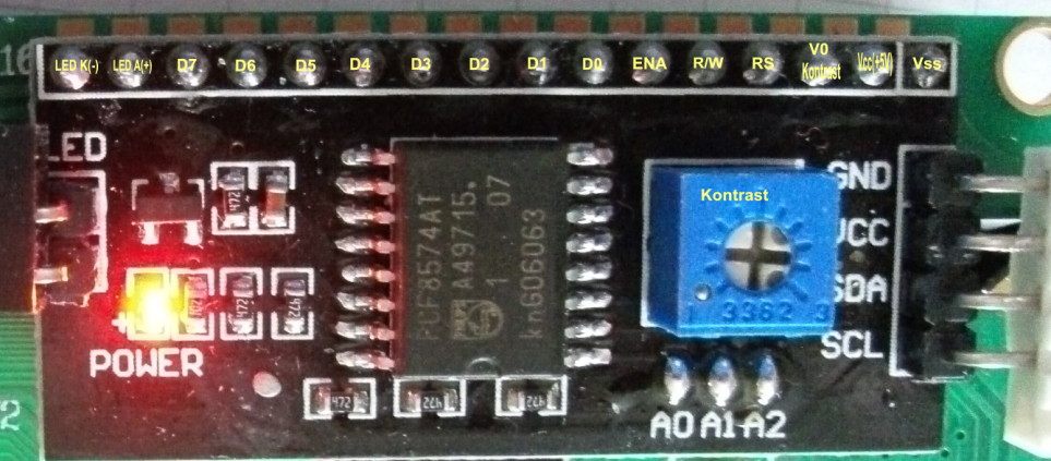
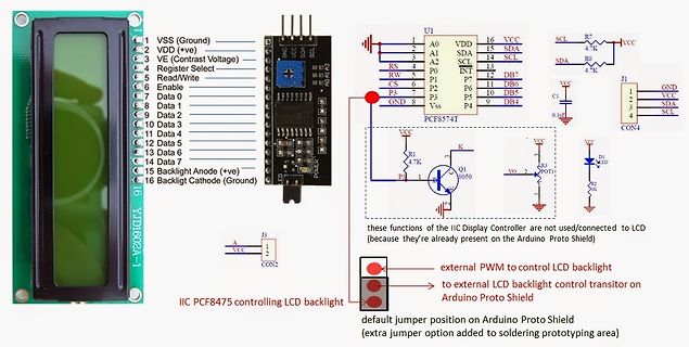
I2C LCD Adapter Modul mit PCF8574AT Chip
LED K(-) LED A(+) D7 D6 D5 D4 D3 D2 D1 D0 ENA R/W RS VO Kontrast Vcc(+5V) Vss LED POWER PCF8574AT A49715. 07 kn606063 GND VCC SDA SCL A0 A1 A2 Kontrast
in „HD44780 I2C Adapter“ · Mikrocontroller und Digitale Elektronik · · Platinenfotos
-
 Bild
Bild
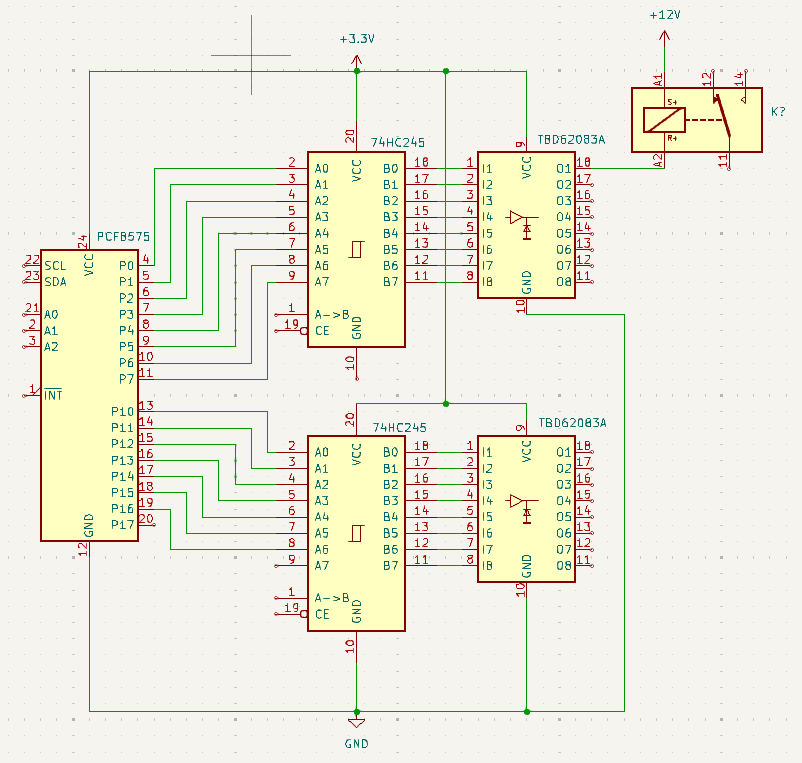
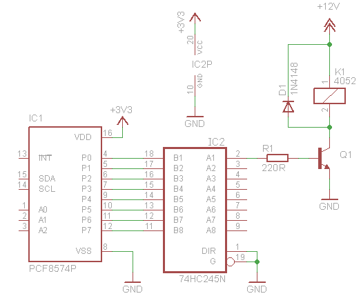
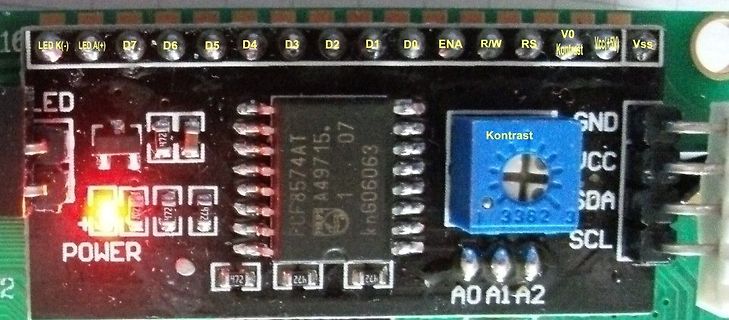
Schaltplan mit Transceivern und Relais
+3.3V, 74HC245, TBD62083A, +12V, K?, S+, R+, 22 SCL, 23 SDA, PCF8574, P0 bis P7, A0 bis A7, INT, 19 CE, A->B, 10 GND, 20 VCC, B0 bis B7, 11, 12, 13, 14, 15, 16, 17, 18, GND
in „Lichtsteuerung über i2c - ULN2803A - S12-100“ · Mikrocontroller und Digitale Elektronik · · Schaltpläne
-
 Bild
Bild
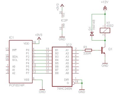
Schaltplan mit PCF8574P und 74HC245N
VCC, IC2P, 10, GND, +12V, K1, 4052, 2, D1, 1N4148, R1, 220R, Q1, GND, IC1, VDD, 16, P0, 4, 18, B1, A1, 2, P1, 5, 17, B2, A2, 3, INT, 13, SDA, 15, SCL, 14, P2, 16, B3, A3, 4, P3, 7, 15, B4, A4, 5, P4, 9, 14, B5, A5, 6, P5, 10, 13, B6, A6, 7, P6, 11, 12, B7, A7, 8, A0, 1, A1, 2, A2, 3, P7, 12, 11, B8, A8, 9, VSS, 8, IC2, DIR, 1, G, 19, 74HC245N, PCF8574P
in „Lichtsteuerung über i2c - ULN2803A - S12-100“ · Mikrocontroller und Digitale Elektronik · · Schaltpläne
-
Datei
SainSmart2004_ATtiny2313.asm
- - - - - - - - - - - - - - - - twimain: cli rcall twiinit rcall twistart ldi temp, 0x70 ; Adresse A0,A1,A2=GND + R/W-Bit (W=0; R=1) rcall twiout brts end ; Wenn NACK (Speicherbit in SREG gesetzt), ret ; dann Sprung zum Ende ; end: rjmp endlos ; twiinit: sbi portb, 7 ; SCL high sbi portb, 5 ; SDA high
in „I2C Display einfache Frage“ · Mikrocontroller und Digitale Elektronik ·
-
Datei
SainSmart2004_ATtiny2313.asm
- - - - - - - - - - - - - - - - twimain: cli rcall twiinit rcall twistart ldi temp, 0x70 ; Adresse A0,A1,A2=GND + R/W-Bit (W=0; R=1) rcall twiout brts end ; Wenn NACK (Speicherbit in SREG gesetzt), ret ; dann Sprung zum Ende ; end: rjmp endlos ; twiinit: sbi portb, 7 ; SCL high sbi portb, 5 ; SDA high
in „Anfänger Will ATtiny2313 mit Display uber I2C verbinden“ · Mikrocontroller und Digitale Elektronik ·
-
Datei
partlist.txt
30.48 15.24) MR270 C29 100n C0805 rcl (66.675 27.94) R0 C30 100n C0805 rcl (64.135 11.43) R0 CON1 SCDA5A0201 SCDA5A0201 SCDA5A0201 (69.85 15.24) R90 D1 BAT42 DO35-10 diode (66.675 49.53) R0 IC2 AT24C512 DIL08 atmel (24.13 38.1) R0 IC3 MEGA48/88/168-AU TQFP32-08 avr-7 (39.37 20.32) R0 IC4 PCF8574T SO16W
in „CP/M auf ATmega88“ · Mikrocontroller und Digitale Elektronik ·
-
 Bild
Bild
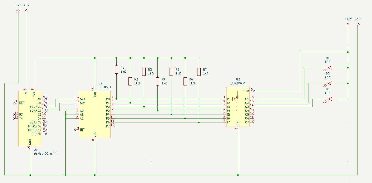
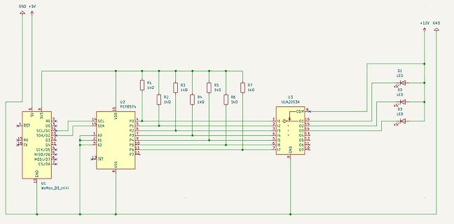
Schaltplan mit WeMos D1 mini und ULN2003A
GND +5V 5V 3V3 U1 WeMos_D1_mini RST SCL/D1 SDA/D2 D3 MISO/D6 MOSI/D7 CS/D8 GND INT VSS U2 PCF8574 P0 P1 P2 P3 P4 P5 P6 P7 SCL SDA A0 A1 A2 VDD R1 1kΩ R2 1kΩ R3 1kΩ R4 1kΩ R5 1kΩ R6 1kΩ R7 1kΩ U3 ULN2003A COM D1 LED D2 LED D3 LED +12V GND
in „PCF8574 mit ULN2003A wird Gestört“ · Mikrocontroller und Digitale Elektronik · · Schaltpläne
-
PDF
I2C_LCD.pdf
V + C1 100n +5V GND R1 10k GND A E GND +5V S IC1 +5V 1 VSS 1 VDD 16 2 VDD I SV2 3 VEE D 4 13 INT P0 4 4 RS 3 P1 5 5 R/W 2 15 SDA P2 6 6 E 6 1 14 SCL P3 7 7 D0 1 P4 9 8 D1 A 1 A0 P5 10 9 D2 P P 2 A1 P6 11 10 D3 I D 3 A2 P7 12 11 D4 D A D 12 D5 C E VSS 8 N +5V 13 D6 L G R3 14 D7 PCF8574P Q1 15 NC 1k BC857 R2 16 NC 17 A SV1 100R 18 C A0 6 5 A1 4 3 A2 2 1 GND I2C Adresse GND 0 4 0 3 0 5 0 R 0 R 0 R 1 1 1 5 +
in „PCF8574 I2c Adapter mit ASM ansteuern“ · Mikrocontroller und Digitale Elektronik ·
-
 Bild
Bild
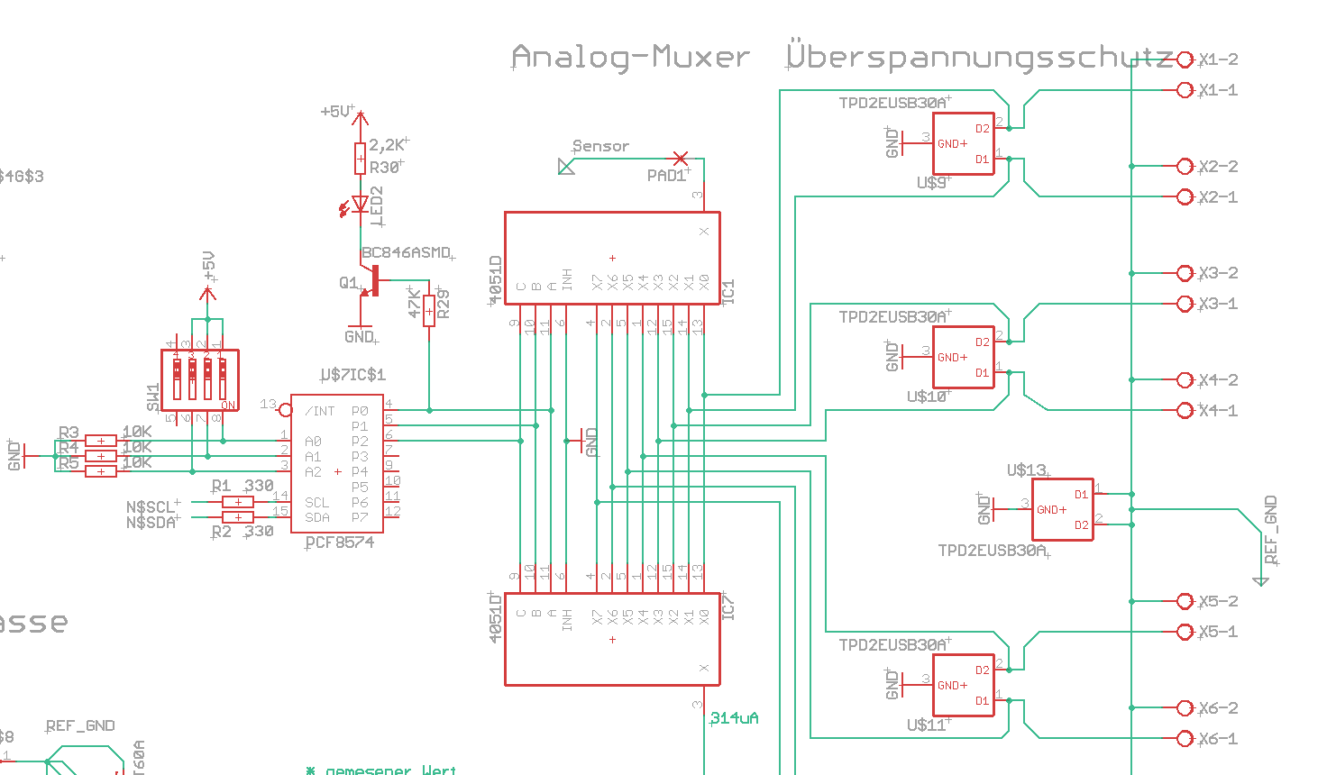
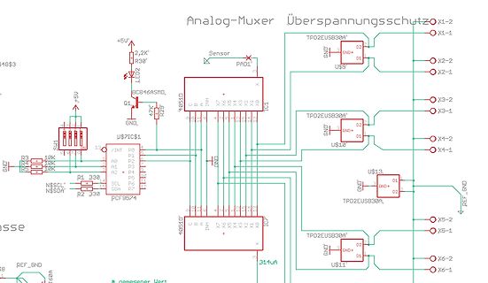
Ausschnitt eines elektronischen Schaltplans
Analog-Muxer Überspannungsschutz X1-2, TPD2EUSB30A, D2, GND+, D1, X2-2, X2-1, U$9, X3-2, X3-1, X4-2, X4-1, TPD2EUSB30A, D2, GND+, D1, U$10, X5-2, X5-1, X6-2, X6-1, TPD2EUSB30A, D2, GND+, D1, U$11, 4051D, IC1, Sensor, PAD1, BC846ASMD, Q1, LED2, R30, +5V, R3, 10K, R4, 10K, R5, 10K, GND, R1 330, PCF8574, SCL, SDA, P0 bis P7, /INT, U$7IC$1, 314uA
in „Fachliteratur Entwurf Blitzductor“ · Analoge Elektronik und Schaltungstechnik · · Schaltpläne
-
Datei
pinout.h
#if v3board //d4 a6 d6 d7 c0 c1 c2 c3 c4 c5 c6 c7 ++ -- rt a7 d5 a5 a4 a3 //Rest Bport a0 a1 d0 c5 c6 c7 led:a0 #define use_lcdili9225 1 //ir #define ir_in_port B #define ir_in_pin 0 //ow #define ds1820_port A #define
in „Header Datei für Konfiguration erstellen“ · Mikrocontroller und Digitale Elektronik ·
-
PDF
I2C.pdf
7 Bit Adr. 8 Bit Adr. Virtual Port Beschreibung HEX BIN HEX BIN A2 A1 A0 0x48 1001.000 0x90 1001.000X 0x50 – 0x5F SC16IS740 (UART) - H H 0x27 0100.111 0x4E 0100.111X 0x60 – 0x75 MCP23017 (16 Bit I/O) H H H 0x20 0100.000 0x40 0100.000X 0x80 – 0x87 PCF8574 (8 Bit I/O
in „CP/M auf ATmega88“ · Mikrocontroller und Digitale Elektronik ·
-
PDF
Display.pdf
5 5 + + C1 JP2 5 1 JP1 + 2 1 3 2 4 JP3 3 E 5 1 5 GND 4 GND S 6 + 5 1 7 6 R A 7 IC1 8 IC2 VDD 16 9 6 LV VOUT 5 10 13 INT P0 4 11 C2 2 CAP+ OSC 7 C3 P1 5 12 15 SDA P2 6 13 4 CAP- V+ 8 T 14 SCL P3 7 14 D 1 2 P4 9 15 1 NC GND 3 1 1 A0 P5 10 S 2 A1 P6 11 ICL7660CPA 3 4 3 A2 P7 12 JP4 1 VSS 8 GND PCF8574T GND GND GND
in „LCD - ich verzweifele“ · Mikrocontroller und Digitale Elektronik ·
-
PDF
DE2012010361.pdf
C4 C5 C6 C7 1 A3V3 4n7 120p 120p 120p 4n7 BSR18A A3V3 = mica 1% C9 Q1 = metal film 1% J4 10n R12 1 4 8 R13 R14 1 1 ISO1 6 C13 U1 = MCP6024 PWM1 6 U2 = MCP6022 U1 U2 100k 1k 7 11 4 U2B 100n 5 3V3 A3V3 LINK J4 P1 J3 P1
-
 Bild
Bild
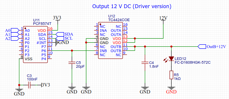
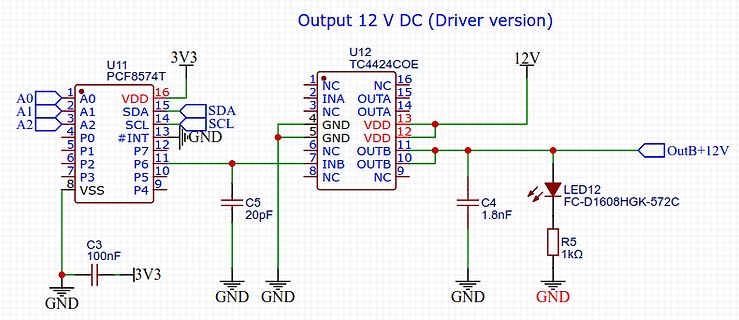
Schaltplan eines 12V DC Treibers
Output 12 V DC (Driver version) U11 PCF8574T A0 A1 A2 P0 P1 P2 P3 VSS 3V3 SDA SCL #INT GND 16 15 14 13 12 11 10 9 U12 TC4424COE NC INA NC GND GND NC INB NC OUTA OUTA VDD VDD OUTB OUTB 1 2 3 4 5 6 7 8 16 15 14 13 12 11 10 9 C5 20pF C3 100nF
in „PCF8574 Optokoppler Input/Output“ · Mikrocontroller und Digitale Elektronik · · Schaltpläne
-
 Bild
Bild
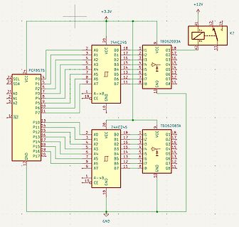
Schaltplan einer Mikrocontroller-Steuerung
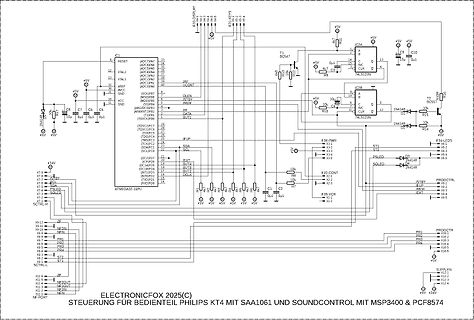
IC1 ATMEGA32-16PU, T1 BC547, T2 BC557, 74LS213A, 74LS213A, 10k, 10uF, F38-DISPLAY, F39-PWR, F32-CONT, F39-VCR, F38-LEDs, F38-SOLFO, ELECTRONICFOX 2025(C) STEUERUNG FÜR BEDIENTEIL PHILIPS KT4 MIT SAA1061 UND SOUNDCONTROL MIT MSP3400 + PCF8574
in „Zeigt her eure Kunstwerke (ab 2023)“ · Projekte & Code · · Schaltpläne