-
Datei
stm32f103xb.h
(2U) #define I2C_SR1_BTF_Msk (0x1UL << I2C_SR1_BTF_Pos) /*!< 0x00000004 */ #define I2C_SR1_BTF I2C_SR1_BTF_Msk /*!< Byte Transfer Finished */ #define I2C_SR1_ADD10_Pos (3U) #define I2C_SR1_ADD10_Msk (0x1UL << I2C_SR1_ADD10_Pos) /*!< 0x00000008 */ #define I2C_SR1_ADD10 I2C_SR1_ADD10_Msk /*!< 10-bit header sent (Master mode) */ #define I2C_SR1_STOPF_Pos (4U) #define I2C_SR1_STOPF_Msk (0x1UL << I2C_SR1_STOPF_Pos) /*!< 0x00000010 */ #define I2C_SR1_STOPF I2C_SR1
in „System Workbench für STM32 Anfängerfragen“ · PC Hard- und Software ·
-
Datei
stm32f103x6.h
(2U) #define I2C_SR1_BTF_Msk (0x1UL << I2C_SR1_BTF_Pos) /*!< 0x00000004 */ #define I2C_SR1_BTF I2C_SR1_BTF_Msk /*!< Byte Transfer Finished */ #define I2C_SR1_ADD10_Pos (3U) #define I2C_SR1_ADD10_Msk (0x1UL << I2C_SR1_ADD10_Pos) /*!< 0x00000008 */ #define I2C_SR1_ADD10 I2C_SR1_ADD10_Msk /*!< 10-bit header sent (Master mode) */ #define I2C_SR1_STOPF_Pos (4U) #define I2C_SR1_STOPF_Msk (0x1UL << I2C_SR1_STOPF_Pos) /*!< 0x00000010 */ #define I2C_SR1_STOPF I2C_SR1
in „System Workbench für STM32 Anfängerfragen“ · PC Hard- und Software ·
-
Datei
Env_I2C_Scanning.asm
_10_10_0 .equ ADR_I2C_RD, 0x95 ; 100_10_10_(1) ; I2C Temp Sensor TMP101 registers Burr Brown .equ ADR_I2C_TEMP, 0x00 ; TI-Sensor Data .equ ADR_I2C_CFG, 0x01 ; TI-Sensor Data_1 ;.equ VAL_I2C_CLKDIV, 0x7C
in „Probleme bei Lattice I2C EFB mit Wishbone Interface“ · FPGA, VHDL & Co. ·
-
PDF
SH7709.pdf
2 R4_BANK0* 3 R5_BANK1* 2 R5_BANK0* 3 R6_BANK1* 2 R6_BANK0* 3 2 3 R7_BANK1* R7_BANK0* R8 R8 R9 R9 R10 R10 R11 R11 R12 R12 R13 R13 R14 R14 R15 R15 SR SR SSR SSR Notes: *1 R0 functions as an index GBR GBR register in the indexed MACH MACH register-indirect addressing mode and indexed GBR- MACL MACL indirect
in „HD6417709A F133B“ · Mikrocontroller und Digitale Elektronik ·
-
Datei
Program1.c
an ein angschlossenes 74HC595 schieberegister void SR_SendByte() { DDR_SSR_G |= SR_G; // G = 0 DDR_SSR_SCL |= SR_SCL; DDR_SSR_SCK |= SR_SCK; DDR_SSR_RCK |= SR_RCK; DDR_SSR_SER |= SR_SER; PORT_SSR_SCL |= SR_SCL; // SCL = 1 PORT_SSR_G &= ~SR_G; PORT_SSR_SCK |= SR_SCK; PORT_SSR_RCK |= SR_RCK; PORT_SSR_SER |= SR_SER; uint8_t v = led1data; uint8_t c = 8; while(c--) { if(v & 0x80) PORT_SSR_SER &= ~SR_SER; else PORT_SSR_SER |= SR_SER; PORT_SSR_SCK ^= SR_SCK; asm volatile
in „Quantum QT1106 Sensor-Chip an AVR usw.“ · Mikrocontroller und Digitale Elektronik ·
-
Datei
wc.txt
:=lo(LED_word); end; procedure LED_off; begin PortC:=(PortC and $F0); PortD:=0; end; procedure LED_SR_next; begin LED_off; if not inctolim(led_row, 11) then led_row:= 0; SR_DATA:= sr_on; SR_CLK:= true; nop; nop; nop; SR_CLK:= false; SR_DATA:= sr_off; LED_word:= LED_word_array[0]; else SR_CLK:= true;
in „Wieder mal DCF“ · Mikrocontroller und Digitale Elektronik ·
-
Datei
wordclock_mega888.PAS
:=lo(LED_word); end; procedure LED_off; begin PortC:=(PortC and $F0); PortD:=0; end; procedure LED_SR_next; begin LED_off; if not inctolim(led_row, 11) then led_row:= 0; SR_DATA:= sr_on; SR_CLK:= true; nop; nop; nop; SR_CLK:= false; SR_DATA:= sr_off; LED_word:= LED_word_array[0]; else SR_CLK:= true;
in „Wer kennt sich aus mit Pascal?“ · Mikrocontroller und Digitale Elektronik ·
-
PDF
ADV7175A.pdf
CLOSED CAPTIONING EVEN FIELD TR1 BIT DESCRIPTION DATA REGISTER 1–0 (CED15–CED00) HSYNC Width (TR11–TR10) (Address [SR4–SR0] = 09–08H) These bits adjust the HSYNC pulsewidth. These 8-bit wide registers are used to set up the closed captioning HSYNC to VSYNC/FIELD Delay Control (TR13–TR12) extended data
-
Datei
digitcommands.c
digitcommands.h" #include "spi.h" extern SPI_HandleTypeDef hspi1; void put2STR(void) { HAL_GPIO_WritePin(SR_STR.port, SR_STR.pin, OFF); HAL_GPIO_WritePin(SR_STR.port, SR_STR.pin, ON); } void switchDigit(uint8_t digitCounter, uint32_t digitValue, uint8_t *array) { // e.g digitValue = 99999 uint8_t dataDigit1
in „Interrupt wird ständig aufgerufen“ · Mikrocontroller und Digitale Elektronik ·
-
PDF
EF28F008SA.pdf
Erase Suspend or deep powerdown modes. Bus Command Comments Operation Write Byte Write Datae 40H (10H) Setup Addresse Byte to be written Write Byte Write Data to be written Addresse Byte to be written Standby/Read Check RY/BY Ý VOH e Ready, VOL e Busy or Read Status Register Check SR.7 1e Ready, 0e
in „Wo ist der Pin1?“ · Mikrocontroller und Digitale Elektronik ·
-
PDF
SR102-110.pdf
SCHOTTKY BARIER RECTIFIER VOLTAGE RANGE 20 to 100 Volts SR102 THRU SR110 CURRENT 1.0 Ampere FEATURES • Fast switching • Low forward voltage • Low power loss for high efficiency • High Surge capability • HighOtemperature Soldering guaranteed: 250 C/10 seconds
in „Dioden: Datenblatt / Vergleichbar“ · Mikrocontroller und Digitale Elektronik ·
-
Datei
twi_bus.c
*/ twi_buf[Rx_Idx2++] = I2C2->DR; SR1Register = 0; SR2Register = 0; if (readyToSend) { if (Rx_Idx2 == 0x10) { sendUDP = 1; } else { sendUDP = 0; } } TWI_SlaveTransactionFinished(); //ADMIN BUS } /* If STOPF =1: EV4 (Slave has detected a
in „stm32 Cortex I2C : Master zieht SCL auf Masse“ · Mikrocontroller und Digitale Elektronik ·
-
Datei
F2_messung_pwm.c
TIM_DIER_UIE; // und Interrupt freigeben } } void TIM6_DAC_IRQHandler(void) // Aufruf mit 1 kHz { if(TIM6->SR & TIM_SR_UIF) { // nur bei überläufen von T16 TIM6->SR = ~TIM_SR_UIF; F2_mess_dauer++; // Messzeit erfassen __ISB(); // gelöschtes Flag abwarten } } // 1,6 - 3 MHz ISR mit T7 erzeugen void init_t7(void
-
Datei
H750_SPI1.c
/* 2020-12-10 Michael Nowak http://www.mino-elektronik.de Alle Angaben ohne Gewaehr ! */ #define TDC7200 #include "system_H750.h" // Befehl und Startadresse ausgeben void TDC_write(uint8_t cmd) { while(!(SPI1->SR & SPI_SR_TXP)); // freies FIFO abwarten *(__IO uint8_t *)&SPI1->TXDR = (uint8_t)(cmd); while(!(SPI1->SR & SPI_SR_TXC)); // Ausgabe abwarten } // RX-FIFO leeren void flush_SPI1(void) { while((SPI1->SR & (SPI_SR_RXWNE
in „Probleme beim STM32H743 & SPI“ · Mikrocontroller und Digitale Elektronik ·
-
Datei
DHT11Routine.s
die wahrscheinlichsten( z.B.Hängenbleiben des ganzen Programms wegen Hardware-Defekt an Sensor) BTSC SR , #C BRA LftmessAbschluss ;Inhalt Abfrage des DHT11-Luftfeuchte-Sensor-Moduls mit 100 Khz / 10usec Interrupt-Grundfrequenz: BTSS MyFlags3,#3 ;LuftFMessg Start Flag. 1=LOS BRA LuftmessFrtg BTSC MyFlags3
in „DHT11 - AusleseRoutine in ASM30 (Assembler für PIC24 oder PIC30)“ · Mikrocontroller und Digitale Elektronik ·
-
PDF
SFH_4301_IR-LED_3mm_OSRAM.pdf
20 µs I = f (T ) erel p F A OHF00777 2 OHF00809 OHF00359 100 10 120 Ι mA Ιerel Ιe F Ιe(100mA) 100 80 80 60 100 R =375K/W thJA 60 40 10-1 40 10-2 20 20 -3 0 10 0 1 2 3 4 00 20 40 60 80 100˚C120 800 850 900 950 1000 nm 1100 10 10 10 10 mA 10 λ ΙF TA Forward Current
in „LED PAD für Eagle?“ · Platinen ·
-
Datei
main.c
define LED5D PD0 #define LED6D PD1 #define LED7C PC4 #define LED8C PC5 #define LED9C PC3 #define LED10C PC2 #define LED11C PC0 #define LED12C PC1 #define SR_SER_DATA PB0 #define LED_HEAD PB1 #define SR_G_NOT PB2 #define SR_RCK PB3 #define SR_SCLEAR_NOT PB4 #define SR_SCK PB5 // experimental //end+++++
in „AVR ATMEGA8 hex file erstellen“ · Mikrocontroller und Digitale Elektronik ·
-
PDF
TDA8706A_2.pdf
hold time 6.5 9.0 − ns d output delay time − 12 19 ns SELECT INPUT SIGNALS SR, SG, SB AND CLP su set-up time SR, SG and with no overlap; see Fig.310 − − ns SB with overlap; see Fig.4 − − − ns r rise time SR, SG and SB 10% to 90% 4 6 − ns f fall time SR, SG and SB 90% to 10% 4
in „TDA8706A Fragen“ · Mikrocontroller und Digitale Elektronik ·
-
PDF
Datenblatt_SAB-C167CR-LM_SiemensSemiconductorGroup.pdf
period tOSC SR 50 1000 200 333 ns 1) 2) High time t1 SR 23 – 10 – ns Low time t SR 23 1) 2) – 10 – ns 2 Rise time t3 SR – 10 2) – 102) ns Fall time t4 SR – 10 2) – 102) ns 1)For temperatures aboveT A= + 85 ˚C the minimum
in „Ersatz für alten Hitach H8/3337 µP?“ · Mikrocontroller und Digitale Elektronik ·
-
Datei
SPI_SLAVE.c
/*SPI0 Peripheral*/ #define PORTSPI0 0 // PORTSPI0 = floor((10-13)/32) = 0 #define PIN0SYNC 10 // Chip Select NPCS[0] => PIN0SYNC = floor(10%32) = 10 #define PIN0SDO 11 // MOSI #define PIN0SDI 12 // MISO => PIN0SDI = floor(12%32) = 12 #define PIN0SCK 13 // Clock
in „AVR32 Problem mit SPI als Slave“ · Mikrocontroller und Digitale Elektronik ·
-
PDF
__Rutenbeck_23510503_BA01.pdf
SR 5TX Please ensure that you read these instructions carefully before commis- GB aufmerksam durch. Ordnungsgemäßer Transport, korrekte Lagerung sioning the REG-Switch SR 5TX GB. The correct transport,
in „LAN-Switch REG von Rutenbeck - Standbyleistung“ · Haus & Smart Home ·
-
Datei
gamer.txt
TEMP, TWSR ; get TWI status andi TEMP, 0xF8 ; mask Bit0...2 (prescaler und reserve-BIT) cpi TEMP, TW_SR_SLA_ACK ; x60 breq TWSI_TW_SR_SLA_ACK cpi TEMP, TW_SR_ARB_LOST_SLA_ACK ; x68 breq TWSI_END cpi TEMP, TW_SR_GCALL_ACK ; x70 breq TWSI_END cpi TEMP, TW_SR_ARB_LOST_GCALL_ACK ; x78 breq TWSI_END cpi TEMP, TW_SR_DATA_ACK ; x80 breq TWSI_TW_SR_DATA_ACK cpi TEMP, TW_SR_DATA_NACK ; x88 breq TWSI_END cpi TEMP, TW_SR_GCALL_DATA_ACK ; x90 breq TWSI_END cpi TEMP, TW_SR_GCALL_DATA_NACK ; x98 breq TWSI_END cpi TEMP,
in „DDS normal ?“ · Mikrocontroller und Digitale Elektronik ·
-
PDF
XL6009_1_1.pdf
Regulator ON) 1.4 EN Pin Threshold VEN V Low (Regulator OFF) 0.8 EN Pin Input Leakage IH V EN=2V (ON) 3 10 uA Current L VEN =0V (OFF) 3 10 uA Max. Duty Cycle DMAX VFB0V 90 % Rev 1.1 www.xlsemi.com 5 XL6009 400KHz60V4ASwitchingCurrentBoost/Buck-Boost/Inverting DC/DC Converter Schottky Diode Selection Table
in „Step-Up Wandler arbeitet nicht mit Schmitt-Trigger“ · Analoge Elektronik und Schaltungstechnik ·
-
PDF
XL6009.pdf
Regulator ON) 1.4 EN Pin Threshold VEN V Low (Regulator OFF) 0.8 EN Pin Input Leakage IH V EN=2V (ON) 3 10 uA Current L VEN =0V (OFF) 3 10 uA Max. Duty Cycle DMAX VFB0V 90 % Rev 1.1 www.xlsemi.com 5 XL6009 400KHz60V4ASwitchingCurrentBoost/Buck-Boost/Inverting DC/DC Converter Schottky Diode Selection Table
in „6-9V auf 12V booster“ · Analoge Elektronik und Schaltungstechnik ·
-
Datei
UART.vhd
downto 0) := x"F0"; signal txsr : std_logic_vector (9 downto 0); signal txbitcnt : integer range 0 to 10 := 10; signal txcnt : integer range 0 to (Quarz_Taktfrequenz/Baudrate); signal txd_tmp :std_logic := '0'; signal rxd_sr : std_logic_vector (3 downto 0) := "1111"; -- Flankenerkennung und Eintakten signal
-
Datei
UART.vhd
signal txsr : std_logic_vector (9 downto 0):= (others=>'1'); signal txbitcnt : integer range 0 to 10 := 10; signal txcnt : integer range 0 to (Quarz_Taktfrequenz/Baudrate)-1; signal txd_tmp :std_logic := '0'; signal rxd_sr : std_logic_vector (3 downto 0) := "1111"; -- Flankenerkennung und Eintakten
-
Datei
mon.txt
Ausdrucks: abcd: :Zahleneingabe normalerweise in hex #12345: :Eingabe einer Dezimalzahl $Rx, $SS, $US, $SR, $PC :Verwendung eines Registerinhalts Operatoren eines Ausdrucks: ( ) + - * / :Grundrechenarten und Klammern (10-fach) - = negieren des Wertes, ~ = invertieren aller Bits eines Wertes ^ = bitweise OR
in „MiniComputer 68k2.0 (MC68HC001)“ · Mikrocontroller und Digitale Elektronik ·
-
Datei
i2c_hw.asm
TWDR has been transmitted (TWEA = 0 ); ACK has been received ; TWI Slave Receiver status codes .equ SR_ADR_ACK = $60 ; Own SLA+W has been received ACK has been returned .equ SR_ADR_ACK_M_ARB_LOST = $68 ; Arbitration lost in SLA+R/W as Master; own SLA+W has been received; ACK has been returned .equ SR_GEN_ACK
in „I²C/TWI in Avr-studio betreiben“ · Mikrocontroller und Digitale Elektronik ·
-
Datei
usart.c
TX USART2->CR1 |= USART_CR1_UE; //enable USART } int SendChar_USART1 (char ch) { while (!(USART1->SR & USART_SR_TXE)); //data transmit register empty? USART1->DR = (ch & 0xFF); //write bytewise return (ch); } int SendChar_USART2 (char ch) { while (!(USART2->SR & USART_SR_TXE)); //data transmit register
in „[STM32] CMD0 liefert immer 0xFF zurück“ · Mikrocontroller und Digitale Elektronik ·
-
Datei
lcd-routines3wks.h
//////////////////////////////////////////////////////////////////////////////// // Anschlüsse von SR an LCD //LCD 7 6 5 4 3 2 1 0 //SR 3 4 5 6 10 11 12 13 //SR 9 auf HIGH // // Pinbelegung für das LCD und SR an verwendete Pins anpassen // Alle MC-Pins müssen am gleichen Port liegen. // //SR1+2 &LCD
in „Bitshift für Schieberegister C-Code“ · Mikrocontroller und Digitale Elektronik ·
-
Datei
interrupt_Haendler.c
void I2C2_EV_IRQHandler(void) { //outpin_enable(&led_4); __IO unsigned long SR1Register = 0; __IO unsigned long SR2Register = 0; #ifdef SLAVE_DMA_USE /* Read SR1 register */ SR1Register = I2C2->SR1; /* If ADDR is set */ if ((SR1Register & 0x0002) == 0x0002) { /* In slave Transmitter
in „STM32 Cortex Timer behindert I2C Interrupt“ · Mikrocontroller und Digitale Elektronik ·
-
 Bild
Bild
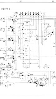
Schaltplan einer elektronischen Schaltung
1.721.315.00 5/36 JSP 1 B R41 4K7 Q1 BC 307 R56 40K D15 R46 40K R4 100K IC 2 D2 44 60 D5 C5 4.7u R35 22K SR-REC SR-STOP D23 BC 307 R14 10K R39 68K C4 47u R2 22K D18 R6 22K R37 22K SR-PLAY R48 47K Q2 BC 307 R2 100K R3 400K MC 14066 SR-FORW R11 4.7K R42 10K R46 100K IC 1 D12 -22V D11 R2 100K R2 100K R32 1K7 SR-REW R40 40K R46 100K D19 D20 D17 R2 10K R93 3K3 Q3 BC 307 IC 6 4N24 R92 3K3 R15 22K R26 22K R16 BC 337 SR-FAD2 R54 4.7K R58 4.7K Q4 BC 307 IC 7 R53 10K SR-LIFT R63 22K R57 22K C2 22u Q16 BC 337
in „Spannungsversorgung EL Folie“ · Analoge Elektronik und Schaltungstechnik · · Schaltpläne
-
PDF
BTS7960_v1.1_2004-12-07.pdf
85°C current I switch active D(LS) 3.0.4 HS pulsed drain current ID(HS) -60 601) A TC < 85°C 1) t = 10ms 3.0.5 LS pulsed drain current ID(LS) -60 60 A pulse 3.0.6 Voltage at SR pin V -0.3 1.0 V SR 3.0.7 Voltage between VS and V VS-V IS -0.3 45 V IS pin 3.0.8 Voltage at IS pin V IS -20 45 V Thermal Maximum
in „H-Brücke für Gleichstrommotor 24V 5A“ · Analoge Elektronik und Schaltungstechnik ·
-
PDF
Infineon-BTS7960-DS-v01_01-en.pdf
85°C current I switch active D(LS) 3.0.4 HS pulsed drain current ID(HS) -60 601) A TC < 85°C 1) t = 10ms 3.0.5 LS pulsed drain current ID(LS) -60 60 A pulse 3.0.6 Voltage at SR pin V -0.3 1.0 V SR 3.0.7 Voltage between VS and V VS-V IS -0.3 45 V IS pin 3.0.8 Voltage at IS pin V IS -20 45 V Thermal Maximum
in „BTS7960 IS Sensor mit abweichenden Werten.“ · Analoge Elektronik und Schaltungstechnik ·
-
PDF
BTS7960_v1.1_2004-12-07.pdf
85°C current I switch active D(LS) 3.0.4 HS pulsed drain current ID(HS) -60 601) A TC < 85°C 1) t = 10ms 3.0.5 LS pulsed drain current ID(LS) -60 60 A pulse 3.0.6 Voltage at SR pin V -0.3 1.0 V SR 3.0.7 Voltage between VS and V VS-V IS -0.3 45 V IS pin 3.0.8 Voltage at IS pin V IS -20 45 V Thermal Maximum
in „H-Brücken IC schalten bei Belastung ab und nicht wieder an“ · Mikrocontroller und Digitale Elektronik ·
-
PDF
Spezifikation.pdf
following a START (S) or active master disables its current-source pull-up circuit. repeated START (Sr) condition as explained in Section This enables other devices to delay the serial transfer by 10.1. The 10-bit addressing does not affect the existing stretching the LOW period of the SCLH signal. The
in „SPI, ISP, USI, TWI, I2C“ · Mikrocontroller und Digitale Elektronik ·
-
PDF
Spezifikation.pdf
following a START (S) or active master disables its current-source pull-up circuit. repeated START (Sr) condition as explained in Section This enables other devices to delay the serial transfer by 10.1. The 10-bit addressing does not affect the existing stretching the LOW period of the SCLH signal. The
-
PDF
Spezifikation.pdf
following a START (S) or active master disables its current-source pull-up circuit. repeated START (Sr) condition as explained in Section This enables other devices to delay the serial transfer by 10.1. The 10-bit addressing does not affect the existing stretching the LOW period of the SCLH signal. The
in „I²c mit Bascom und ATmega“ · Mikrocontroller und Digitale Elektronik ·
-
PDF
Spezifikation.pdf
following a START (S) or active master disables its current-source pull-up circuit. repeated START (Sr) condition as explained in Section This enables other devices to delay the serial transfer by 10.1. The 10-bit addressing does not affect the existing stretching the LOW period of the SCLH signal. The
in „Reset auf I2C-Bus“ · Mikrocontroller und Digitale Elektronik ·
-
PDF
Philips_Semiconductors_-_I2C_Bus_Specification_v2.1.pdf
following a START (S) or active master disables its current-source pull-up circuit. repeated START (Sr) condition as explained in Section This enables other devices to delay the serial transfer by 10.1. The 10-bit addressing does not affect the existing stretching the LOW period of the SCLH signal. The
in „GND-Fäche sinnvoll???“ · Platinen ·
-
PDF
Spezifikation.pdf
following a START (S) or active master disables its current-source pull-up circuit. repeated START (Sr) condition as explained in Section This enables other devices to delay the serial transfer by 10.1. The 10-bit addressing does not affect the existing stretching the LOW period of the SCLH signal. The
in „i2c und Takt“ · Mikrocontroller und Digitale Elektronik ·
-
PDF
Spezifikation.pdf
following a START (S) or active master disables its current-source pull-up circuit. repeated START (Sr) condition as explained in Section This enables other devices to delay the serial transfer by 10.1. The 10-bit addressing does not affect the existing stretching the LOW period of the SCLH signal. The
-
PDF
Spezifikation.pdf
following a START (S) or active master disables its current-source pull-up circuit. repeated START (Sr) condition as explained in Section This enables other devices to delay the serial transfer by 10.1. The 10-bit addressing does not affect the existing stretching the LOW period of the SCLH signal. The
in „I2C Speicher HotSwap?“ · Mikrocontroller und Digitale Elektronik ·
-
PDF
Spezifikation.pdf
following a START (S) or active master disables its current-source pull-up circuit. repeated START (Sr) condition as explained in Section This enables other devices to delay the serial transfer by 10.1. The 10-bit addressing does not affect the existing stretching the LOW period of the SCLH signal. The
in „I²C Bus Schnittstelle extern ?“ · Mikrocontroller und Digitale Elektronik ·
-
PDF
I2C_BUS_SPECIFICATION_3.pdf
following a START (S) or active master disables its current-source pull-up circuit. repeated START (Sr) condition as explained in Section This enables other devices to delay the serial transfer by 10.1. The 10-bit addressing does not affect the existing stretching the LOW period of the SCLH signal. The
in „SPI oder TWI“ · Mikrocontroller und Digitale Elektronik ·
-
PDF
Spezifikation.pdf
following a START (S) or active master disables its current-source pull-up circuit. repeated START (Sr) condition as explained in Section This enables other devices to delay the serial transfer by 10.1. The 10-bit addressing does not affect the existing stretching the LOW period of the SCLH signal. The
in „Unterschied Defintion I²C und SPI“ · Mikrocontroller und Digitale Elektronik ·
-
PDF
i2c_bus_specification_3.pdf
following a START (S) or active master disables its current-source pull-up circuit. repeated START (Sr) condition as explained in Section This enables other devices to delay the serial transfer by 10.1. The 10-bit addressing does not affect the existing stretching the LOW period of the SCLH signal. The
in „IIC-Bus Verständnisfrage“ · Mikrocontroller und Digitale Elektronik ·
-
PDF
I2C_SPEC.pdf
following a START (S) or active master disables its current-source pull-up circuit. repeated START (Sr) condition as explained in Section This enables other devices to delay the serial transfer by 10.1. The 10-bit addressing does not affect the existing stretching the LOW period of the SCLH signal. The
in „I2C abstrakt“ · Mikrocontroller und Digitale Elektronik ·
-
PDF
I2C_SPEC.pdf
following a START (S) or active master disables its current-source pull-up circuit. repeated START (Sr) condition as explained in Section This enables other devices to delay the serial transfer by 10.1. The 10-bit addressing does not affect the existing stretching the LOW period of the SCLH signal. The
in „I2C programmieren lernen“ · Mikrocontroller und Digitale Elektronik ·
-
PDF
39340011.pdf
following a START (S) or active master disables its current-source pull-up circuit. repeated START (Sr) condition as explained in Section This enables other devices to delay the serial transfer by 10.1. The 10-bit addressing does not affect the existing stretching the LOW period of the SCLH signal. The
in „Problem mit I²C-Device“ · Mikrocontroller und Digitale Elektronik ·