-
PDF
0900766b8065a805.pdf
27 VBUS UART D- 2 5 D- USB USB Function TXD 26 D+ 3 4 Transceiver Controller 25 GND 4 D+ RXD 6 5 640B 576B RTS 24 D1 D2 D3 1024B TX RX EEPROM Buffer Buffer CTS 23 Figure 1. Example System Diagram Rev. 1.1 9/05 Copyright © 2005 by Silicon Laboratories CP2102 CP2102 2 Rev. 1.1 CP2102 T ABLE OF C ONTENTS
in „DC DC Wandler Pins“ · Analoge Elektronik und Schaltungstechnik ·
-
PDF
0900766b8065a805.pdf
27 VBUS UART D- 2 5 D- USB USB Function TXD 26 D+ 3 4 Transceiver Controller 25 GND 4 D+ RXD 6 5 640B 576B RTS 24 D1 D2 D3 1024B TX RX EEPROM Buffer Buffer CTS 23 Figure 1. Example System Diagram Rev. 1.1 9/05 Copyright © 2005 by Silicon Laboratories CP2102 CP2102 2 Rev. 1.1 CP2102 T ABLE OF C ONTENTS
in „DC DC Wandler Pins“ · Analoge Elektronik und Schaltungstechnik ·
-
PDF
MAX1270-MAX1271B.pdf
1) Resolution 12 Bits MAX127_A ±0.5 Integral Nonlinearity INL MAX127_B ±1.0 LSB Differential Nonlinearity DNL No missing codes over temperature ±1 LSB MAX127_A ±3 Unipolar Offset Error MAX127_B ±5 LSB MAX127_A ±5 Bipolar MAX127_B ±10 Channel-to-Channel Offset Error Unipolar
in „Max1270 Eingang auf mind. 0,8V ?“ · Mikrocontroller und Digitale Elektronik ·
-
PDF
ASMC-QxB2-Txxxx.pdf
integrating sphere at mono pulse conditions. 2. Tolerance = ±12% PartNumberingSystem A S M C - Q X B 1 - T X X X 2 3 4 5 Packaging Option Color Bin Selection Max. Flux Bin Min. Flux Bin LED Chip Color Table2.AbsoluteMaximumRatings(T =25°C) A Parameters ASMC-QxB2-Txxxx DCForwardCurrent [1] 150mA PeakForwardCurrent
in „[V] 0,5W LEDs ROT“ · Markt ·
-
PDF
FCPF11N60B.pdf
Thermal Resistance, Junction-to-Ambient 62.5 62.5 °C/W ©2004 Fairchild Semiconductor Corporation Rev. B, March 2004 F C Electrical Characteristics T = 25°C unless otherwise noted P C Symbol Parameter Test Conditions Min Typ Max Units 1 1 N Off Characteristics 6 0 BV Drain-Source Breakdown Voltage V GS
in „Kühlkörper Dimensionieren“ · Mikrocontroller und Digitale Elektronik ·
-
PDF
le26r81b.pdf
Technische Daten Bildschirmgröße 66 cm Bildformat 16:9 LCD-TV Auflösung (Pixel) 1.366 x 768 LE-26R81B Helligkeitswert 450 cd/m² The Art of Design – Die elegante R8-Serie von Samsung ist das Bild Kontrastverhältnis Dynamische Kontrasteinstellung: 5.000:1 Highlight in jedem Raum – egal ob Designer Store
in „Brauchbarer Monitor?“ · Offtopic ·
-
PDF
-
PDF
-
PDF
SM08B-SRSS-TB.pdf
) 1,500 3,000 Top entry type 8 BM08B-SRSS-TB SM08B-SRSS-TB 7.0(.276) 10.0(.394) 1,500 3,000 9 BM09B-SRSS-TB SM09B-SRSS-TB 8.0(.315) 11.0(.433) 1,500 3,000 B 10 BM10B-SRSS-TB SM10B-SRSS-TB 9.0(.354) 12.0(.472) 1,500 3,000 11 BM11B-SRSS-TB SM11B-SRSS-TB 10.0(.394) 13.0(.512) 1,500 3,000 ) 6 12 BM12B-SRSS-TB SM12B-SRSS-TB 11.0(.433) 14.0(.551) 1,500 3,000 5 . 13 BM13B-SRSS-TB SM13B-SRSS-TB 12.0(.472) 15.0(.591) 1,500 3,000 4 14 BM14B-SRSS-TB
in „[V] EB85-A GPS-Empfaenger“ · Markt ·
-
PDF
tlv320aic23b.pdf
range, A-weighted (see Note 4) AVDD = 2.7 V TBD dB 1 kHz, 0 dB –88 –80 AVDD = 3.3 V dB Total harmonic distortion 1 kHz, −3 dB −92 −86 1 kHz, 0 dB −85 AVDD = 2.7 V dB 1 kHz, −3 dB −88 Power supply rejection ratio 1 kHz, 100 mV 50 dB pp DAC channel separation
in „Brauche ich zwei Enable für BCLK? Darf man das So machen?“ · FPGA, VHDL & Co. ·
-
PDF
tlv320aic23b.pdf
range, A-weighted (see Note 4) AVDD = 2.7 V TBD dB 1 kHz, 0 dB –88 –80 AVDD = 3.3 V dB Total harmonic distortion 1 kHz, −3 dB −92 −86 1 kHz, 0 dB −85 AVDD = 2.7 V dB 1 kHz, −3 dB −88 Power supply rejection ratio 1 kHz, 100 mV 50 dB pp DAC channel separation
-
PDF
Terminal_V1.9b.pdf
Terminal_V1.9b.pdf
in „Hargassner Pelletheizung Betriebsdatenerfassung“ · Haus & Smart Home ·
-
PDF
B400_NTC-02_Serie.pdf
where: The temperature tolerances are plotted in the graphs on the A, B, C, D, A 1, B1, C1and D a1e constant values previous page. depending on the material concerned; see table below. Example: at 0 °C, assume X = 5%, Y = 0.89% and R refis the resistance value at a reference
in „Temperatur Messung mit Mega8 und NTC-Widerstand 4,7k“ · Analoge Elektronik und Schaltungstechnik ·
-
PDF
tlv320aic23b.pdf
range, A-weighted (see Note 4) AVDD = 2.7 V TBD dB 1 kHz, 0 dB –88 –80 AVDD = 3.3 V dB Total harmonic distortion 1 kHz, −3 dB −92 −86 1 kHz, 0 dB −85 AVDD = 2.7 V dB 1 kHz, −3 dB −88 Power supply rejection ratio 1 kHz, 100 mV 50 dB pp DAC channel separation
in „Mit welcher Frequenz muss jetzt der Muxer laufen?“ · FPGA, VHDL & Co. ·
-
PDF
w78c31B.pdf
W78C31B 8-BIT MICROCONTROLLER GENERAL DESCRIPTION The W78C31B microcontroller supplies a wider frequency range than most 8-bit microcontrollers on the market. It is compatible with the industry standard 80C31
in „Formel für Kondensatoren für Quartz“ · Mikrocontroller und Digitale Elektronik ·
-
PDF
MSV30245_Schematic_RevB.pdf
A B C D E VCC R26 VCC 2 1 VCC Debugger/Programmer Interface 100K ICC R14 R25 1 100K J3 0 2 1 + + 2 BUSY CE S5-5 SCLK1 3 + + 4 RxD1 I2S Bus JP3 CE 5 6 VSelect Not 5 8 GND 7 + + 8 RESET Populated 9 + + 10
in „m16C on Chip Programmierung“ · Mikrocontroller und Digitale Elektronik ·
-
 Bild
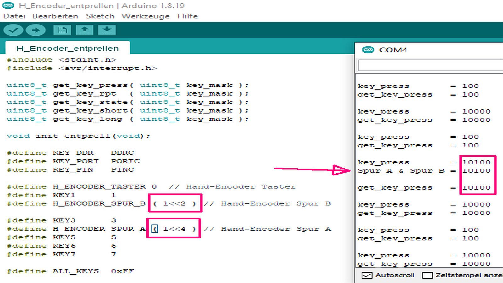
Arduino Code und Serienmonitor-Ausgabe
H_Encoder_entprellen | Arduino 1.8.19 Datei Bearbeiten Sketch Werkzeuge Hilfe COM4 key_press = 100 get_key_press = 100 key_press = 10000 get_key_press = 10000 key_press = 100 get_key_press = 100 key_press = 10100 get_key_press = 10100 key_press = 10000 get_key_press = 10000 key_press = 100 get_key_press = 100 key_press = 10000 get_key_press = 10000
in „Peter Dannegger´s ( PeDa ) Entprellroutine in ein Arduino Sketch einbinden“ · Mikrocontroller und Digitale Elektronik · · Screenshots

-
 Bild
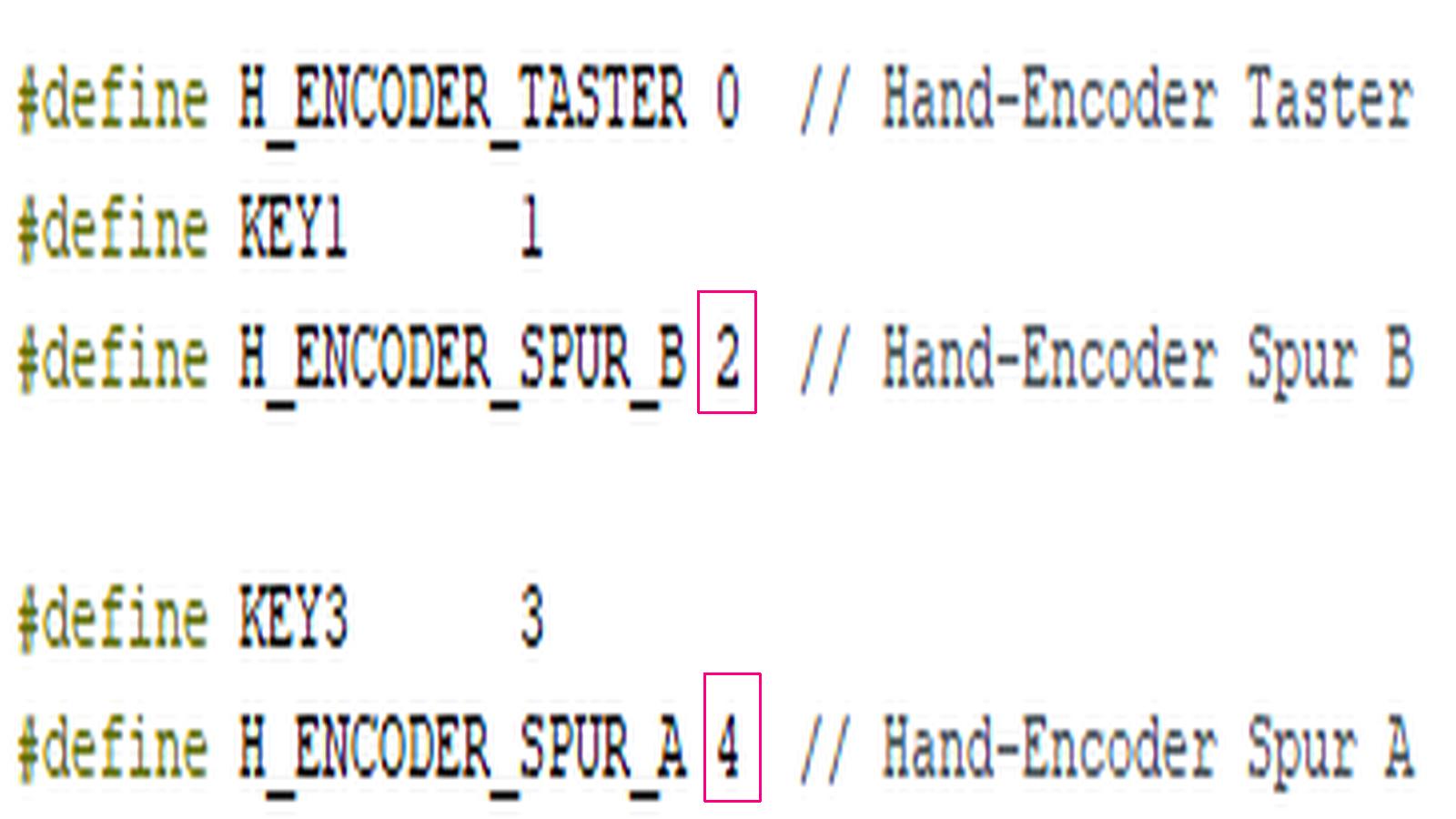
C-Code Definitionen für Encoder-Pins
#define H_ENCODER_TASTER 0 // Hand-Encoder Taster #define KEY1 1 #define H_ENCODER_SPUR_B 2 // Hand-Encoder Spur B #define KEY3 3 #define H_ENCODER_SPUR_A 4 // Hand-Encoder Spur A
in „Peter Dannegger´s ( PeDa ) Entprellroutine in ein Arduino Sketch einbinden“ · Mikrocontroller und Digitale Elektronik · · Screenshots

-
 Bild
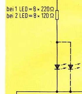
Ausschnitt eines Schaltplans mit LED-Berechnungen
bei 1 LED = 8 x 220 Ω bei 2 LED = 8 x 120 Ω
in „Bastelei identifizieren“ · Offtopic · · Schaltpläne
-
 Bild
Vergleich zweier Leiterplatten-Ausschnitte mit markierten Bauteilen
1.4 R47 PWR ACT J1 PWR IN KE 2G653 1.3
in „[S] Raspberry PI 3B+“ · Markt · · Platinenfotos

-
PDF
RFM12B_Schema_2.pdf
nINT/VDI 11 PCB Rule i 14 ANT nSEL 8 nSEL Draht Antenne SCK 9 SCK 83mm Länge ab Print 10 SDI RFM12B SDI 1 SDO SDO 4 DCLK/CFIL/FFIT 6 nRES nRES 5 CLK 2 nIRQ N N nIRQ G G 2 7 C13 1 22n Ker. GND GND GND
in „RFM12B: Startprobleme > evt. Layout Schuld?“ · Mikrocontroller und Digitale Elektronik ·
-
PDF
ST4209L1206-B.pdf
ST4209L1206-B.pdf
in „B&R Schrittmotorsteuerung & Nanotec Motor“ · Mikrocontroller und Digitale Elektronik ·
-
PDF
0900766b8078cf19.pdf
Resistance Weld Thru-Hole Crystal Model: HC49SLF RoHS Compliant / Pb Free Rev. 2/27/2006 Page 1 of 2 http://www.foxonline.com/need_a_sample.htm FEATURES OPTIONS • Low Cost • Tolerances to 10 PPM • Stocking Standard (see page 2) • Stabilities to 5 PPM • Fundamental to 50 MHz • Temperatures to -40ºC ~ +105ºC • Resistance Weld • 2.5mm Height Max (HC49SSLF) • PART NUMBER Learn More - Internet Required Part Number Model Number Frequency Range (MHz) 277LF-Frequency-xxxxx HC49SLF 3.200 ~ 70.000 1 • STANDARD SPECIFICATIONS PARAMETERS MAX (unless otherwise noted) Frequency Range 3.200 ~ 70.000 MHz Frequency
in „ATMEGA32 16MHz Quarz welche Kondensatoren?“ · Mikrocontroller und Digitale Elektronik ·
-
PDF
B154EW04_VB.pdf
] VDD=+3.3V R G B R G B R G B R G B R G B R G B R G B R G B R G B R G B R G B R G B R G B R G B R G B R G B R G B R G B R G B R G B R G B R G B R G B R G B R G B R G B R G B R G B R G B R G B R G B R G B R G B R G B R G B R G B R G B R G B R G B R G B R G B R G B R G B R G B R G B R G B R G B R G B R G B R G B R G B R G B R G B R G B R G B R G B R G B R G B R G B R G B [32x32 Mosaic pattern] VDD=+3.3V B154EW04 V.B Page
in „Notebookdisplay als "normalen" Bildschirm verwenden“ · PC Hard- und Software ·
-
Datei
FT2232H_minimal_B.vhd
IEEE.STD_LOGIC_1164.ALL; use IEEE.NUMERIC_STD.ALL; use ieee.math_real.all; entity FT2232H_minimal_B is Port( clk100: in std_logic; -- FT2232H D: out std_logic_vector(7 downto 0); RXF: in std_logic; TXE: in std_logic; RD: out std_logic; WR: out std_logic; SIWU: out std_logic; CLKOUT: in std_logic; --60MHz FTDI OE: out std_logic; PWRSAV: out std_logic); end FT2232H_minimal_B; architecture Behavioral of FT2232H_minimal_B is component fifo_generator_0 IS PORT( rst : IN STD_LOGIC; wr_clk : IN STD_LOGIC; rd_clk : IN STD_LOGIC; din : IN STD_LOGIC_VECTOR(7 DOWNTO 0); wr_en : IN
-
PDF
Prism_Audio_LA_100B.pdf
- O/P +V I/P -V 0V 50V0uF + - 1000uF 50V +
in „100W-Verstärker“ · Analoge Elektronik und Schaltungstechnik ·
-
PDF
B400_NTC-02_Serie.pdf
where: The temperature tolerances are plotted in the graphs on the A, B, C, D, A 1, B1, C1and D a1e constant values previous page. depending on the material concerned; see table below. Example: at 0 °C, assume X = 5%, Y = 0.89% and R refis the resistance value at a reference
in „NTC Berechnung nach Steinhart and Hart, 2. Gleichung geht nicht!“ · Mikrocontroller und Digitale Elektronik ·
-
PDF
0900766b806aae79.pdf
SIB/DIS/TIS Series - Socket Strips 2,54mm pitch Single-in-line strips Dual- & triple-in-line strips SIB Series SIB Series single-in-line Strips breakable and solid insulator available SIB-1xx-Sxxx-xx Number of contacts standard breakable available 20; 32 and 40 001 Standard terminal 047 Low profile terminal Number of contacts Unless otherwise specifically either breakable or requested, the strips will be solid available delivered either in solid or breakable plastic depending on availability of the insulator bodies. 02 to 40 DIS & TIS Series DIS Series dual and triple row 2,54mm grid DIS-2xx-Sxxx-xx
-
PDF
2450LP14B100.PDF
"High Frequency Ceramic Solutions" 2.4 GHz Low Pass Filter P/N 2450LP14B100 Detail Specification: 06/23/03 Page 1 of 2 General Specifications Part Number 2450LP14B100 Impedance 50 Ω Frequency (MHz) 2400 - 2500 Operating Temperature -40 to +85°C Insertion Loss 0.50 dB max. Reel Quantity 4,000 Return Loss 14 dB min. Attenuation (min.) 35 dB @ 2 x fo Terminal Configuration 25 dB @ 3 x fo Attenuation (min.) No. Function Input Power 3 Watts max. 1 GND 2 IN 3 GND Mechanical Dimensions 4 GND In mm 5 OUT L 0.063
-
PDF
CP_Robot_12b_sch.pdf
REFSW_R 27OuInt10 Su10 In 0 S 100n 10Sn 100n 10Sn 100n S S p G PSK03 a a a a a S X5 P P P P P r IC2B P 5 PaSsu1p 0 i 36 Out 0 Pas 02 x MOTOR_A0 Pas 03 a HAREROD MOTOR_A1 38 Out 0 Pas 04 Pas 05 Marcus Hasenstab 40 Out 0 CP_Robot MOTOR_B0 info@harerod.de PSK05 MOTOR_B1 42 Out 0 Stepper-Driver 2 TMCM-30X
-
PDF
B300_PXA_ELKOS_ECC.pdf
using conductive polymer as electrolyte @Rated voltage range : 2.5 to 25V dc , case size range : F4B5.2L to F10B12.2L @Suitable for DC-DC converters, voltage regulators and decoupling applications used to computer motherboards etc. @RoHS Compliant ? SPECIFICATIONS Items Characteristics Category - 55
in „Ladungspumpe: welchen Low-ESR Kondensator nehmen?“ · Mikrocontroller und Digitale Elektronik ·
-
PDF
P82B96_7.pdf
C P82B96PN P82B96PN −40 °C to +85 °C P82B96TD P82B96T −40 °C to +85 °C P82B96TD/S900 P82B96T −40 °C to +125 °C P82B96_7 © NXP B.V. 2009. All rights reserved. Product data sheet Rev. 07 Ñ 12 February 2009 2
in „18 x SHT11 an welchem Mikrocontroller“ · Mikrocontroller und Digitale Elektronik ·
-
PDF
KS0070B_V0.pdf
KS0070B 16COM / 80SEG DRIVER & CONTROLLER FOR DOT MATRIX LCD INTRODUCTION KS0070B is a dot matrix LCD driver & controller LSI which is fabricated by low power CMOS technology. It is capable of displaying 1 or
in „EA DIP162-D / STK500 / ATmega8 initialisierung“ · Mikrocontroller und Digitale Elektronik ·
-
PDF
11B25_UpdateBeschreibung.pdf
Projekt / Historie EleLa Projekt / Historie EleLa Datum Status B/F Bezeichnung Beschreibung Version fertig 25.11.2011 fertig Bug Bestellung, BestellNr-Export Wenn der Lieferant 1 und Lieferant 2 mit dem gleichen Lieferant eingetragen wurde wie exportiert V1.2.11B25
in „EleLa - Elektronik Lagerverwaltung ab V1.2.11A26“ · Projekte & Code ·
-
PDF
364-57379-TDA9983B.pdf
for 16-bit and 32-bit modes are shown in Figure 11. AP0/WS left channel right channel ACLK APx 0R B23L B0L L 0L 0L B23R B0 R 0R 0R 0R B23L x = 1, 2, 3, 4 001aag915 a. 32-bit mode AP0/WS left channel right channel ACLK APx B0R B15L B14L B13L B2L B1L B0L B15R B14R B13R B2R B1R B0R B15L x = 1, 2, 3, 4
in „Pollin - Receiver-Mainboard mit Twin DVB-[T,C] Tuner, NXP PNX8950EH“ · Mikrocontroller und Digitale Elektronik ·
-
Datei
SST25VF016B.c
-------------------------------------------------------------------------- ** File name: SST25VF016B.c ** Descriptions: SST25VF016B SPI flash Function ** **-------------------------------------------------------------------------------------------------------- ** Created by: AVRman ** Created date:
in „Font in SPI Flash schreiben“ · Mikrocontroller und Digitale Elektronik ·
-
Datei
SST25VF016B.h
-------------------------------------------------------------------------- ** File name: SST25VF016B.c ** Descriptions: SST25VF016B SPI flash Function ** **-------------------------------------------------------------------------------------------------------- ** Created by: AVRman ** Created date:
in „Font in SPI Flash schreiben“ · Mikrocontroller und Digitale Elektronik ·
-
Datei
test_18_glcd128b.c
set_portpin_output(LED_RED); set_portpin_output(LED_GREEN); #if RAMSIZE > 1024 both(); init_glcd128b(DEFAULT_GLCD128B); glcd128b_set_contrast(16); glcd_set_color(1); glcd_clrscr(); glcd_scrollmode(); set_outchar_routine(glcd_char); enable_tick(KHZ); enable_interrupts(); green(); glcd_set_color(2); glcd_box
in „Atmel Studio: "Standard" SW-Routinen aus einem Pool verwenden“ · Mikrocontroller und Digitale Elektronik ·
-
Datei
C--TS_LC7981_b.h
************** * LC7981/HD61830 Graphics +Text LCD Driver * * Configured for the Samsung LJ41-00192B 160x80 monochrome graphics lcd. * * Written by Vanya A. Sergeev - <vsergeev@gmail.com> * * February 16, 2007 * geändert Juni+Juli 2009 Wolfgang *******************************************************
in „Sende/Empfangsvorgang mittels nur 1St. µC“ · Mikrocontroller und Digitale Elektronik ·
-
Datei
B17-Opt-Install-Description.txt
Rohde & Schwarz I/Q IF option for CMU-200 (B17) or CRTU-RU (B7) Complete with all micro SMB cables for the CMU-200, for the A3 RX/TX module, you should be able to use your current cables at A3-X39 and A3-X37, these cables are not supplied. However
in „CMU200 Erfahrungen und Modifikationen“ · HF, Funk und Felder ·
-
PDF
B400_SHSA5_dbd.pdf
v Bauteil direkt auf Platinen bestücken. e Impedanz bei rF>97% > 150 kOhm n Andere Ausführungen, z.B. mit Anschlussleitung r und Stecker, sind auf Anfrage ebenfalls lieferbar. d Interdigitalstruktur Leitwertschalter, ca. 10 µS Ä e max. Auswerte- Res. Sensor < 0,8 Vpp ~/= c spannung Leitwert < 2 Vpp
in „Wassersensor“ · Analoge Elektronik und Schaltungstechnik ·
-
Datei
DS18B20_2.asm
Byte schreiben ret Read_Temp: ;rcall SkipRom ;Skip Rom senden rcall SelectRom ldi accu,0xBE ;Vom DS18B20 Ram, die Temperatur auslesen rcall One_Wire_Write ;1 Byte schreiben timer,2 ;2µs delay rcall One_Wire_Read ;1-Wire Byte lesen mov RawLow,accu ;Byte 0 des Scratchpad rcall One_Wire_Read ;1-Wire Byte
in „Probleme mit "MatchRom" bei DS18B20“ · Mikrocontroller und Digitale Elektronik ·
-
Datei
DS18B20_2.asm
Byte schreiben ret Read_Temp: rcall SkipRom ;Skip Rom senden ;rcall SelectRom ldi accu,0xBE ;Vom DS18B20 Ram, die Temperatur auslesen rcall One_Wire_Write ;1 Byte schreiben timer,2 ;2µs delay rcall One_Wire_Read ;1-Wire Byte lesen mov RawLow,accu ;Byte 0 des Scratchpad rcall One_Wire_Read ;1-Wire Byte
-
PDF
xbee_DS18B20.pdf
einzelnen Messwert auslesen data[ ] via Messwert an data[ ] Frame 0x10 senden anhängen +3V gnd 4.7k DS18B20 Temperatursensoren DS18B20 DS18B20 RTS SLEEP DQ 15 16 15 13 XBee ATMega48 2 3 6 2 3 4 INT0 Stromversorgung, 10k 470 470 470 1k 100k Quarz 3.686.400 MHz und Kondensatoren sind nicht dargestellt ! BC
in „XBee for NewBees (DOS-Tool zum Testen von XBee's im API-Modus)“ · Projekte & Code ·
-
PDF
0900766b80365be8.pdf
Wilderstraat 52 N-1601 FREDRIKSTAD SP11 8QZ HAMPSHIRE D-88069 TETTNANG F-14200 HEROUVILLE ST. CLAIR B-9400 APPELTERRE sales@mascot.no Norway UK Germany FRANCE Belgium Phone: +47 69 36 43 00 +44 (0)1264 357177 +49 7542 953540 +33 (0)2 31 06 04 40 +32 (0)54 300 442 Fax: +47 69 32 94 33 +44 (0)1264 364055
in „DC Spannungsversorgung für kap. Beschleunigungssensor“ · Mikrocontroller und Digitale Elektronik ·
-
PDF
MAX127-MAX128B.pdf
UNITS ACCURACY (Note 1) Resolution 12 Bits MAX127A/MAX128A ±1/2 Integral Nonlinearity INL LSB MAX127B/MAX128B ±1 Differential Nonlinearity DNL ±1 LSB MAX127A/MAX128A ±3 Unipolar Offset Error MAX127B/MAX128B ±5 LSB MAX127A/MAX128A ±5 Bipolar MAX127B/MAX128B ±10 Channel-to-Channel Offset Unipolar ±0.1
in „Probleme mit Max127 (i2c adc) und m644p (gcc)“ · Mikrocontroller und Digitale Elektronik ·
-
PDF
DS18B20_readme.pdf
Vereinfachte Temperaturmessung mit mehreren DS18B20 ohne Kenntnis der ROM-Codes in C Vereinfachte Temperaturmessung mit mehreren DS18B20 ohne Kenntnis der ROM-Codes in C Die Temperaturmessung mit den DS18B20 Sensoren ist an sich eine sehr komfortable
in „Vereinfachte Methode zur Temperaturmessung mit mehreren DS18B20 in C“ · Projekte & Code ·
-
Datei
sketch_juli13b_Regent.ino
// Solar Warmwasserboiler Regent 1500W Stufen 240W / 360W / 480W #include <Wire.h> #include <LiquidCrystal_I2C.h> // A4=SDA, A5=SCL https://arduinogetstarted.com/tutorials/arduino-lcd-i2c LiquidCrystal_I2C lcd(0x27, 16, 2); //Brabander I2C address 0x27, 16 column and 2 rows int resetoutpin = 7; unsigned long startreset; unsigned long tagezaehler; int netzpin = 8; bool netzeingang; unsigned long netzeingangist; unsigned long netzeingangstart; unsigned long netzentprellt; // Insel int inselpin = 9; bool inselbetrieb; // Multivibrator / Taktgeber unsigned long mvstart; unsigned long mvist; unsigned long
in „Arduino nano arbeitet ohne Display nicht.“ · Mikrocontroller und Digitale Elektronik ·
-
Datei
-v_-Wl-v_Toolchain_b.txt
------ Rebuild All started: Project: TCA_Timertakt, Configuration: Release AVR ------ Build started. Project "TCA_Timertakt.cppproj" (Clean target(s)): Target "Clean" in file "C:\Program Files (x86)\Atmel\Studio\7.0\Vs\Compiler.targets" from project "C:\Users\Worker\Documents\Atmel Studio\7.0\WorkSpace_AVR128DB64\TCA_Timertakt\TCA_Timertakt\TCA_Timertakt.cppproj" (entry point): Using "RunCompilerTask" task from assembly "C:\Program Files (x86)\Atmel\Studio\7.0\Extensions\Application\AvrGCC.dll". Task "RunCompilerTask" Shell Utils Path C:\Program Files (x86)\Atmel\Studio\7.0\shellUtils C:\Program Files (x86)
in „GCC v14 Release“ · Mikrocontroller und Digitale Elektronik ·
-
Datei
AVR64EA32_b.cpp
/* * AVR64EA32 * RTC_PIT_002.cpp */ #include <avr/io.h> #include <util/delay.h> #include <avr/interrupt.h> #include <util/atomic.h> void initInternal20MHzOscillator (void) { // 20MHz mittels Fuse ausgewählt // CPU_CCP = CCP_IOREG_gc; CLKCTRL.OSCHFCTRLA = CLKCTRL_RUNSTDBY_bm | CLKCTRL_AUTOTUNE_0_bm; // Main Clock Prescaler CPU_CCP = CCP_IOREG_gc; CLKCTRL.MCLKCTRLB = 0; // disable Prescaler, Default 6 // wait internal oscillator is stable while(!(CLKCTRL.MCLKSTATUS & CLKCTRL_OSCHFS_bm)) { ; } // Select Internal Clock Source and enable Pin Clock Out CPU_CCP = CCP_IOREG_gc; CLKCTRL.MCLKCTRLA = (CLKCTRL_CLKSEL_OSCHF_gc
in „AVR64EA28: PIT-Interrupt“ · Mikrocontroller und Digitale Elektronik ·