-
PDF
2706_SCH.pdf
_ _ R11 C21 XOUT24M XIN24M SDT_D13 SDT_D14 SDT_D1 4 VDDQ1 VSSQ 51 SDT_D14 P D NC 16 XOUT24M ROCK2706 SDT_D14 81 VCC SDT_D2 DQ1 DQ14 SDT_D13 H S 0.1uF C26 0.1uF VDD 17 VDD SDT_D15 80 SDT_D15 5 DQ2 DQ13 50 C23 0.1uF 2 2 LCD_D4 18 LCD_D4 VDD 79 VDD C22 0.1uF GND 6 VSSQ1 VDDQ4 49 VCC D2 D1 用 LM489时, R49,C64, C29不贴 LCD_D5 19 78 GND SDT_D3 7 DQ3 DQ12 48 SDT_D12 IN5819 IN5819 LCD_D6 20 LCD_D5 VSS 77 VCC C24 0.1uF SDT_D4 8 47 SDT_D11 用 EMA201时, R48,R14
in „Handydummy (Attrappe)mit richtigem Display - Sony Ericsson Vivaz“ · Mikrocontroller und Digitale Elektronik ·
-
Datei
Bauteile.txt
1. 19"-Adapterkarte DIN 41612 C64 a+c, Verlängerung um ca. 22cm, alle Signale einzeln schaltbar 2. Nullkraft-Sockel breit, 24-polig, für 12-18mm breite ICs, neu 4. 10W-NF-Verstärker A210K (TBA810S) mit Kühlkörper, neu, 6 Stück 6. 2N3655
-
Datei
OLED_LCD_Testcode_mit_Drehgeber.ino
/* This is an example of how to use the OLED 128x64 I2C with SSD1306 driver using the Adafruit library. It also applies to the 128x32 version, but not all components would fit the smaller screen. Pins: * GND = GND * VCC = 5V * SCL = A5 * SDA = A4 You
in „Arduino OLED Display hakt bei zu schneller Werteingabe“ · Mikrocontroller und Digitale Elektronik ·
-
Datei
ssd1306_interrupt_Beispiel.ino
/* This is an example of how to use the OLED 128x64 I2C with SSD1306 driver using the Adafruit library. It also applies to the 128x32 version, but not all components would fit the smaller screen. Pins: GND = GND VCC = 5V SCL = A5 SDA = A4 You can connect
in „Arduino OLED Display hakt bei zu schneller Werteingabe“ · Mikrocontroller und Digitale Elektronik ·
-
PDF
memcpy_log_cl19.pdf
and Host Processor AVX Support is used (QxHost with Intel, and march=native with gcc) 80 cl is MS 64 bit cl 19.27 icl is Intel 64 bit icl 19.0 l gcc is Mingw 64 bit 9.2 y C mm256_* use AVX 32 Byte load/store with prefetch (pf) and s 60 t with or without cache (stream) B 40 20 0 64 128 256 512 1024 2048
-
PDF
cxd2951-commands.pdf
24bits) 22 23 24 25 M 024bits) 26 27 28 af08MSbits) -total 11bits- 29 a (11bits) f1 30 af03LSbits) t (2bits) 31 CRC (16bits) 32 t: Complementary data for parity check C: Bits 23 and 24 of TLM (reserved)
in „DCF77 Auswertung (ein bisschen anders)“ · Mikrocontroller und Digitale Elektronik ·
-
PDF
schematic-T962.pdf
29 BCP68 R 4 P0.6/MOSI0/CAP0.2/AD1.0 30 B R28 10 11 B P0.26/AD0.5 P0.27/AD0.0/CAP0.1/MAT0.1 15 1k C15 P0.30/AD0.3/EINT3/CAP0.0 32 5.0V 62 P1.24/TRACECLK 28 2 7 1 7 U3 AT24C02C XTAL1 P1.25/EXTIN0 24 R 4 R 4 P1.26/RTCK 64 LCD GND Z1 11.0592MHz P1.27/TDO 5 SDA VCC 8 2.54-2x10P C14 61 XTAL2 1 6 k P1.28
-
PDF
STM32F10xxx__20xxx__21xxx_L1xxxx_Cortex-M3_programming_manual.pdf
as shown in Figure 3 and Figure 4. Figure 3. APSR, IPSR and EPSR bit assignments 31 30 29 28 226 25 24 23 16 15 10 9 8 0 APSR N Z C V Q Reserved IPSR Reserved ISR_NUMBER EPSR Reserved ICI/IT T Reserved ICI/IT Reserved Figure 4. PSR bit assignments 31 30 29 28 27 26 25 24 23 16 15 10 9 8 0 N Z C V Q ICI
in „Einstieg in STM32 : STM32F103C8T6 --> Kompilieren und Flashen?“ · Mikrocontroller und Digitale Elektronik ·
-
Datei
LED_CUBE.txt
, 0x5f, 0x5f, 0x00, 0x00, // ! 0x00, 0x03, 0x00, 0x03, 0x00, 0x14, 0x7f, 0x14, 0x7f, 0x14, // "# 0x24, 0x2a, 0x7f, 0x2a, 0x12, 0x23, 0x13, 0x08, 0x64, 0x62, // $% 0x36, 0x49, 0x55, 0x22, 0x50, 0x00, 0x05, 0x03, 0x00, 0x00, // &' 0x00, 0x1c, 0x22, 0x41, 0x00, 0x00, 0x41, 0x22, 0x1c, 0x00, // () 0x14,
in „LED-Cube Effekte weiter per Knopfdruck“ · Mikrocontroller und Digitale Elektronik ·
-
Datei
SSD1306_driver.inc
// 0x70 .db 0x18,0x3C,0x24,0xA4,0xF8,0xFC,0x84,0x00 // 0x71 .db 0x44,0x7C,0x78,0x44,0x1C,0x18,0x00,0x00 // 0x72 .db 0x48,0x5C,0x54,0x54,0x74,0x24,0x00,0x00 // 0x73 .db 0x00,0x04,0x3E,0x7F,0x44,0x24,0x00,0x00 // 0x74 .db 0x3C
in „[ASM] SSD1306 text library für oled displays + AVR 0- und 1-Series“ · Projekte & Code ·
-
 Bild
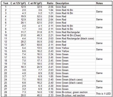
Tabelle mit Messwerten von Kapazitäten und LEDs
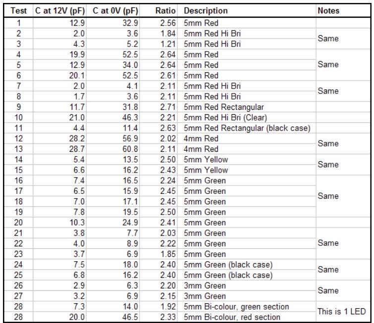
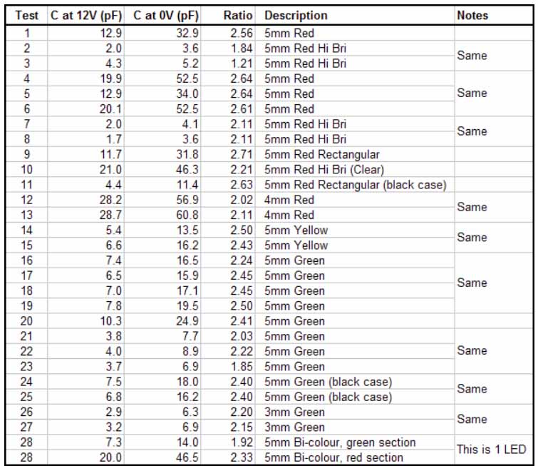
Test C at 12V (pF) C at 0V (pF) Ratio Description Notes 1 12.9 32.9 2.56 5mm Red 2 2.0 3.6 1.84 5mm Red Hi Bri Same 3 4.3 5.2 1.21 5mm Red Hi Bri 4 19.9 52.5 2.64 5mm Red 5 12.9 34.0 2.64 5mm Red Same 6 20.1
in „Liste gängiger Kapazitätsdioden“ · HF, Funk und Felder · · Diagramme
-
Datei
Luftsensor.ino
0x00, 0x7F, 0x10, 0x28, 0x44, 0x00 }, // k { 0x00, 0x00, 0x41, 0x7F, 0x40, 0x00 }, // l { 0x00, 0x7C, 0x04, 0x18, 0x04, 0x78 }, // m { 0x00, 0x7C, 0x08, 0x04, 0x04, 0x78 }, // n { 0x00, 0x38, 0x44, 0x44, 0x44, 0x38 }, // o { 0x00, 0xFC, 0x24, 0x24, 0x24, 0x18 }, // p { 0x00, 0x18, 0x24, 0x24, 0x18,
in „China Arduino zu kleiner flash Speicher?“ · Mikrocontroller und Digitale Elektronik ·
-
PDF
ADCINC.pdf
K Incremental ADC Copyright © 2002-2013 Cypress Semiconductor Corporation. All Rights Reserved. PSoC Blocks API Memory (Bytes) Pins (per Analog External Resources Digital CT Analog SC Flash RAM I/O) Modulators (1st or 1st and 2nd Order) 2nd 1st 2nd 1st 2nd CY8C29xxx, CY8C24x94, CY8C23x33, CY7C64215, CY8CLED04/08/16, CY8CLED0xD, CY8CLED0xG, CY8CTST120, CY8CTMG120, CY8CTMA120, CY8C28x45, CY8C28x43, CY8C28x52, CY8CPLC20, CY8CLED16P01 1 0 1 2 273 322 8 1 CY8C27/24/22xxx, 1 0 1 2 226 275 8 1 CY8CLED08 See AN2239, ADC Selection Guide for other converters. For one or more fully configured
in „Beispiel Anwendungen/Application zu ADCs - Abtastrate & Auflösung“ · Mikrocontroller und Digitale Elektronik ·
-
PDF
cp2102n-datasheet.pdf
GQFN24 4 — Yes Yes -40 to +85 °C QFN24 CP2102N-A02-GQFN20 4 — — Yes -40 to +85 °C QFN20 Note: 1.Devices with the same ordering part number may have different types of pin 1 indicators. However, all of these
-
PDF
cp2102n-datasheet.pdf
GQFN24 4 — Yes Yes -40 to +85 °C QFN24 CP2102N-A02-GQFN20 4 — — Yes -40 to +85 °C QFN20 Note: 1.Devices with the same ordering part number may have different types of pin 1 indicators. However, all of these
in „[V] 10 St. Silabs CP2102N-A01 QFN20 USB-to-UART bridge controller.“ · Markt ·
-
PDF
cp2102n-datasheet.pdf
GQFN24 4 — Yes Yes -40 to +85 °C QFN24 CP2102N-A02-GQFN20 4 — — Yes -40 to +85 °C QFN20 Note: 1.Devices with the same ordering part number may have different types of pin 1 indicators. However, all of these
in „[V] 10 St. Silabs CP2102N-A01 QFN20 USB-to-UART bridge controller. (10€)“ · Markt ·
-
PDF
cp2102n-datasheet.pdf
GQFN24 4 — Yes Yes -40 to +85 °C QFN24 CP2102N-A02-GQFN20 4 — — Yes -40 to +85 °C QFN20 Note: 1.Devices with the same ordering part number may have different types of pin 1 indicators. However, all of these
in „[V] 15St. Silabs CP2102N-A01 QFN20 USB-to-UART bridge controller.“ · Markt ·
-
PDF
cp2102n-datasheet.pdf
GQFN24 4 — Yes Yes -40 to +85 °C QFN24 CP2102N-A02-GQFN20 4 — — Yes -40 to +85 °C QFN20 Note: 1.Devices with the same ordering part number may have different types of pin 1 indicators. However, all of these
in „Frage zu CP2102N und CP2104“ · Mikrocontroller und Digitale Elektronik ·
-
PDF
ATMEGA_128.pdf
available on ourwebsite at www.atmel.com. 1 Pin Configurations Figure 1. Pinout ATmega128 K S O I) C M D D 0 1 2 3 4 5 6 7T/T / C C C C C C C C 0 1 2 ) D D D D D D D D A A A C D F ( A(A ( ( A(A ( ( ( D ( ( ( V N R F F F F F F F F7 N C A A A A G A P P P P P P P P G V P P P 6 6 6 6 6 5 5 5 5 5 5 5 5 5
in „ATMEGA128 Board im Neuhold Newsletter 2/2011“ · Mikrocontroller und Digitale Elektronik ·
-
PDF
mc3362.pdf
Indicator 39K 8.2k 0.01 Audio Operating Device Temperature Range Package Lp = 680 H Cp = 180pF MC3362DW SO–24L TA= – 40 to +85⋅C MC3362P Plastic DIP ⊕ Motorola, Inc. 1996 Rev 2 MOTOROLA ANALOG IC DEVICE DATA 1 MC3362 MAXIMUM RATING (A = 25⋅C, unless otherwise noted) Rating Pin Symbol Value Unit Power Supply
-
PDF
at98c51ed2.pdf
Memory Size and I/O Pins Package Flash (Bytes) XRAM (Bytes) Total RAM (Bytes) I/O PLCC44/VQFP44/DIL40 64K 1792 2048 34 PLCC68/VQFP64 64K 1792 2048 50 2 AT89C51RD2/ED2 4235G–8051–08/05 AT89C51RD2/ED2 Block Diagram Figure 1. Block Diagram r a X b x x C SS C C E e R T V V E P T T K (2) (2) (1) (1)(1) (1) (
in „Mikrocontrollerboard: Funktioniert das?“ · Mikrocontroller und Digitale Elektronik ·
-
PDF
at98c51ed2.pdf
Memory Size and I/O Pins Package Flash (Bytes) XRAM (Bytes) Total RAM (Bytes) I/O PLCC44/VQFP44/DIL40 64K 1792 2048 34 PLCC68/VQFP64 64K 1792 2048 50 2 AT89C51RD2/ED2 4235G–8051–08/05 AT89C51RD2/ED2 Block Diagram Figure 1. Block Diagram r a X b x x C SS C C E e R T V V E P T T K (2) (2) (1) (1)(1) (1) (
in „Temperatur ohne AD-Eingang messen“ · Mikrocontroller und Digitale Elektronik ·
-
PDF
at98c51ed2.pdf
Memory Size and I/O Pins Package Flash (Bytes) XRAM (Bytes) Total RAM (Bytes) I/O PLCC44/VQFP44/DIL40 64K 1792 2048 34 PLCC68/VQFP64 64K 1792 2048 50 2 AT89C51RD2/ED2 4235G–8051–08/05 AT89C51RD2/ED2 Block Diagram Figure 1. Block Diagram r a X b x x C SS C C E e R T V V E P T T K (2) (2) (1) (1)(1) (1) (
in „Displaybeleuchtung faden ohne Analog I/O“ · Mikrocontroller und Digitale Elektronik ·
-
PDF
at98c51ed2.pdf
Memory Size and I/O Pins Package Flash (Bytes) XRAM (Bytes) Total RAM (Bytes) I/O PLCC44/VQFP44/DIL40 64K 1792 2048 34 PLCC68/VQFP64 64K 1792 2048 50 2 AT89C51RD2/ED2 4235G–8051–08/05 AT89C51RD2/ED2 Block Diagram Figure 1. Block Diagram r a X b x x C SS C C E e R T V V E P T T K (2) (2) (1) (1)(1) (1) (
in „Displaybeleuchtung mit PWM dimmen“ · Mikrocontroller und Digitale Elektronik ·
-
PDF
at98c51ed2.pdf
Memory Size and I/O Pins Package Flash (Bytes) XRAM (Bytes) Total RAM (Bytes) I/O PLCC44/VQFP44/DIL40 64K 1792 2048 34 PLCC68/VQFP64 64K 1792 2048 50 2 AT89C51RD2/ED2 4235G–8051–08/05 AT89C51RD2/ED2 Block Diagram Figure 1. Block Diagram r a X b x x C SS C C E e R T V V E P T T K (2) (2) (1) (1)(1) (1) (
in „8051: An Port 0 kann nichts ausgegeben werden“ · Mikrocontroller und Digitale Elektronik ·
-
PDF
at98c51ed2.pdf
Memory Size and I/O Pins Package Flash (Bytes) XRAM (Bytes) Total RAM (Bytes) I/O PLCC44/VQFP44/DIL40 64K 1792 2048 34 PLCC68/VQFP64 64K 1792 2048 50 2 AT89C51RD2/ED2 4235G–8051–08/05 AT89C51RD2/ED2 Block Diagram Figure 1. Block Diagram r a X b x x C SS C C E e R T V V E P T T K (2) (2) (1) (1)(1) (1) (
in „8051: An Port 1 nur 3.5V anstatt 5V ?“ · Mikrocontroller und Digitale Elektronik ·
-
PDF
181861-da-01-de-GRAFIKDISPL_240X128_SW_WS_POS_TOUCH.pdf
Out Output voltage for LC driving 24 N.C. not connected Pinbelegung ist in der Tabelle 5 RESET - L: Reset 25 N.C. not connected 6 BAUD0 In Baud Rate 0 26 N.C. not connected rechts angegeben. 8 BAUD2 In Baud Rate 2 28 N.C. not connected
in „EA eDip240-7“ · Mikrocontroller und Digitale Elektronik ·
-
Datei
24c16_la_1km.txt
,Read,ACK 24.474565416666668,2231,0xAB,0x00,Read,ACK 24.474595250000000,2231,0xAB,0x00,Read,ACK 24.474625249999999,2231,0xAB,0x64,Read,NAK 24.496358666666666,2232,0xAA,0xA8,Write,ACK 24.496429833333334,2233,0xAB,
-
 Bild
Screenshot eines Log-Fensters einer Datenbank-Software
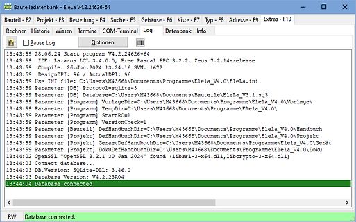
BauteileDatenbank - EleLa V4.2.24626-64 Bauteil - F2 Projekt - F3 Bestellung - F4 Gehäuse - F6 Kiste - F7 Typ - F8 Adresse - F9 Extras - F10 Rechner Historie Wissen Termine COM-Terminal Log Datenbank Info 13:43:59 28.06.24 Start program V4.2.24626-64 13:43:59 IDE: Lazarus LCL 3.4.0.0, Free Pascal FPC 3.2.2, Zeos 7.2.14-release 13:43:59 Compile: 26.Jun.2024 13:24:16 SVN: 1672 13:43:59 DesignDPI: 96 / ActualDPI: 96 13:43:59 Use INI file: C:\Users\M43668
in „EleLa - Elektronik Lagerverwaltung V4.0“ · Projekte & Code · · Screenshots
-
Datei
D_Listing.txt
0009 TBLRD*+ 138: movf TABLAT, 0, 0 0056 50F5 MOVF 0xff5, W, ACCESS 139: movwf curr_byte+1, 1 0058 6F64 MOVWF 0x64, BANKED 140: /* skip two bytes since it's stored as a 32bit int */ 141: tblrdpostinc 005A 0009 TBLRD*+ 142: tblrdpostinc 005C 0009 TBLRD*+ 143: _endasm 144: //prom = data_ptr->from; 145: /
in „PIC18F4550 - PIC macht "nix"“ · Mikrocontroller und Digitale Elektronik ·
-
PDF
cc1100.pdf
22.1 0xC8 24.2 0xCC 25.8 0xC9 25.8 10 0xC2 27.1 0xC0 29.2 0xC3 31.1 0xC0 32.3 Table 30: Optimum PATABLE Settings for Various Output Power Levels and Frequency Bands SWRS038C Page 49 of 96 CC1100 315 MHz 433 MHz
in „Scrambler für Funkstrecke“ · Mikrocontroller und Digitale Elektronik ·
-
Datei
webpage_V1.3.h
0xC6,0xC5,0xF5,0x72,0x9D,0x3E,0x1B,0x15,0x13,0x0B,0x09,0x12,0x3F, 0x3D,0x37,0x1E,0x11,0x2B,0x35,0x38,0x35,0x2E,0x22,0x1D,0x1B,0x18,0x0F,0x10,0x06, 0x2C,0x39,0x34,0x0B,0x1E,0x2F,0x38,0x3C,0x38,0x2F,0x24,0x1D
in „AVR für wenig Geld im LAN“ · Mikrocontroller und Digitale Elektronik ·
-
PDF
DGF-12232-S1FBLY-325-17231-1006.pdf
6.10 6.50 Contrast K θ=0° 1.23 5.79 5.87 -- φ=0° Frame freq. fF -- 32 64 128 Hz Response ton o -- 32 250 20 C ms time off -- 87 250 Viewing 20 C 30 82 -- Deg. θ2-θ1 Angle ϕ 60 81 -- DATAVISION 06/01/11 6 / 25 SPECIFICATIONS FOR LIQUID CRYSTALDISPLAY MODULE MODELNO: DGF-12232
in „Datenbild für LCD“ · Mikrocontroller und Digitale Elektronik ·
-
PDF
MGA52543.pdf
and Output VSWR vs. Figure 24. Current vs. V . d Frequency. 5 MGA-52543 Typical Scattering Parameters T C 25°C, V = 5.0d, I = 53 mAd Z = 50 O , (from S and Noise Parameters in ICM test fixture) Freq s (m) s (a) s (dB) s (m) s (a)
in „Wie ist ein MMIC intern aufgebaut?“ · HF, Funk und Felder ·
-
Datei
font6x8s.c
{0x00, 0x00, 0x03, 0x00, 0x03, 0x00}, // """ {0x00, 0x14, 0x3E, 0x14, 0x3E, 0x14}, // "#" {0x00, 0x24, 0x4A, 0xFF, 0x4A, 0x32}, // "$" {0x00, 0x23, 0x13, 0x08, 0x64, 0x62}, // "%" {0x00, 0x36, 0x49, 0x55, 0x22, 0x50}, // "&" {0x00, 0x00, 0x00, 0x03, 0x00, 0x00}, // "'" {0x00, 0x00, 0x1C, 0x22, 0x41,
in „Fragen zu einem GLCD“ · Mikrocontroller und Digitale Elektronik ·
-
Datei
uint32.S
uint32_t cnt=0; 64: 20 e0 ldi r18, 0x00 ; 0 66: 30 e0 ldi r19, 0x00 ; 0 68: 40 e0 ldi r20, 0x00 ; 0 6a: 50 e0 ldi r21, 0x00 ; 0 for(;;){ PORTB=cnt;//unteres Byte von cnt an PORTB 6c: 28 bb out 0x18, r18 ; 24 PORTB=cnt>
in „AVR-GCC: Zugriff auf Bytes in uint16, uint32.“ · Mikrocontroller und Digitale Elektronik ·
-
PDF
OPTREX_F-51320AE_TechSpec.pdf
...................................................................................................24 Revision History Rev. Date Page Comment F-51320GNB-LW-AEN (AE) No. 2005-0308 OPTREX CORPORATION Page 1/24 1.General Specifications Operating Temp. : min. 0°C ~max. 50°C Storage Temp. : min. -20°C ~max
in „Pollin Grafik LCD-Modul OPTREX F-51320AE“ · Mikrocontroller und Digitale Elektronik ·
-
PDF
CoolRoadRunnerIII-HB-2.pdf
10 GND PERR NC SDONE 11 STOP NC LOCK GND 12 NC TRDY GND DEVSEL 13 FRAME GND IRDY NC 14 GND AD16 NC C/BE2 15 AD18 NC AD17 GND 16 AD21 AD20 GND AD19 17 NC AD23 AD22 NC 18 IDSEL0 GND IDSEL IDSEL2 19 AD24 C/BE3 VI/O IDSEL3 20 GND AD26 AD25 GND 21 AD29 +5 Volts AD28 AD27 22 +5 Volts AD30 GND AD31 23 REQ0
in „Embedded PC erkennt keine Festplatte“ · PC Hard- und Software ·
-
PDF
US5717962.pdf
437/66 [75] Inventors: ToyojiSasaki;HiroshiYamada,both ofHachrop,Japan F O R E I G N P A T E N T D O C U M E N T S 64-170331/1989Japan . [3] Assignee:IOlympusOpticalCotd,Tokyo. 1-124838 5/1989 Japan, apan OTHER PUBLICATIONS [211 Arm-9191822545 MCI" User‘s Guide (Harris); “P-Type MOS Controlled Filed:
in „Projekt: Leistungsstarkes Blitzgerät aus 12 Volt“ · Analoge Elektronik und Schaltungstechnik ·
-
PDF
msp430f413.pdf
meters, counter applications, handheld meters, etc. AVAILABLE OPTIONS PACKAGED DEVICES TA PLASTIC 64-PIN QFP (PM) PLASTIC 64-PIN QFN (RTD) MSP430C412IPM MSP430C412IRTD§ MSP430C413IPM MSP430C413IRTD§ −40°C to 85°C MSP430F412IPM MSP430F412IRTD MSP430F413IPM MSP430F413IRTD MSP430F415IPM MSP430F415IRTD§
in „MSP430F413 Analog eingänge“ · Mikrocontroller und Digitale Elektronik ·
-
PDF
MAX749.pdf
A R SENSE= 0.25 -5V ( TRANSISTOR = ZTX750 ( 350 TRANSISTOR = ZTX750 T250 T E E 300 R R U200 U 250 C -12V C D150 A 200 -12V O O L L 150 100 -24V 100 -24V 50 -48V 50 -48V 0 0 2 3 4 5 6 2 3 4 5 6 INPUT VOLTAGE (V) INPUT VOLTAGE (V) ______________________________________________________________________
in „Suche Spannungs Konverter“ · Analoge Elektronik und Schaltungstechnik ·
-
PDF
MAX749.pdf
A R SENSE= 0.25 -5V ( TRANSISTOR = ZTX750 ( 350 TRANSISTOR = ZTX750 T250 T E E 300 R R U200 U 250 C -12V C D150 A 200 -12V O O L L 150 100 -24V 100 -24V 50 -48V 50 -48V 0 0 2 3 4 5 6 2 3 4 5 6 INPUT VOLTAGE (V) INPUT VOLTAGE (V) ______________________________________________________________________
in „Transistor für MAX749“ · Analoge Elektronik und Schaltungstechnik ·
-
Datei
Helvetica_12.C
66, 241, 81, 62, 10, 5, 0, 0, /* CH_24 934 "dollar" */ 0, 64, 56, 85, 225, 80, 149, 67, 0, /* CH_25 943 "percent" */ 0, 0, 152, 72, 97, 1, 2, 2, 52, 148, 200, 0, 0, 0, /* CH_26 957 "ampersand" */ 0, 0, 65, 161, 48, 148, 50, 25, 19, 0, 0,
in „C -> Zeichen aus Font suchen / rechnen?!“ · Mikrocontroller und Digitale Elektronik ·
-
PDF
schema_stm32_primer2_1_2.PDF
VCC2V8 VCC5_RLink VCC2V8 6 60 3 5 GND 1 26 1 4 USBVSS f A 1 2 PA7 / DTC 1 C1 USBVCC USBVCC D D D D PA6 / DTC 25 VCC5_USB_RLink 5 USBVDD V V V V PA5 / DTC 24 RESET R1 100nF 2 USBD- 2 USBDM PA4 / DTC 23 10K 2 USBD+ 3 22 USBDP PA3 / DTC 21 12MHZ_5V 63 PA2 / DTC 20 64 OSCIN PA1
in „STM32 USB Virtual COM Port“ · Mikrocontroller und Digitale Elektronik ·
-
PDF
AN_Hybrid_Kit_for_HP2_module_V1.1.pdf
FLTn RST_INn P0.6 P7.0 FLTn FLTn_uC GPTA24 AN20 SUPPLY GND_ANA_uC RST_INn P0.7 P7.1 R212TP21 GPTA21 GPTA20 AN21 TEMP_HP1 PWMUB P7.2 TP14 1k69 RST_INn_uC GPTA21 AN22 TEMP_HP1 PWMUB P1.0 P7.3 1u/10V/X5R C83 GPTA22 AN23 TempBoard TEMP_BOARD
in „Linksammlung für Leistungselektronik“ · Mikrocontroller und Digitale Elektronik ·
-
PDF
PDFresult.pdf
9 72 SEG02 COM08 10 71 SEG01 COM09 11 70 SEG00 COM10 12 69 COM00 COM11 13 68 COM01 COM12 14 W742E/C811 67 COM02 66 COM13 15 COM03 COM14 16 100-pin QFP 65 COM04 COM15 17 64 COM05 RA0 18 63 COM06 RA1 19 62 COM07 RA2 20 61 VLCD1 [Data_IO] RA3 21 60 CP RB0 22 59 CN RB1 23 58 P13 [mode] RB2 24 57 P12 RB3
in „Pocket Comm One µC“ · Mikrocontroller und Digitale Elektronik ·
-
 Bild
Tabelle mit Messwerten von Kapazitäten und LEDs
Test C at 12V (pF) C at 0V (pF) Ratio Description Notes 1 12.9 32.9 2.56 5mm Red 2 2.0 3.6 1.84 5mm Red Hi Bri Same 3 4.3 5.2 1.21 5mm Red Hi Bri 4 19.9 52.5 2.64 5mm Red 5 12.9 34.0 2.64 5mm Red Same 6 20.1
in „Liste gängiger Kapazitätsdioden“ · HF, Funk und Felder · · Diagramme
-
PDF
BE-412-B-MONITOR-HEIDENHAIN-MANUAL.pdf
Betriebserde Rechner: X21 = PLC-Ausgang Rot X22 = PLC-Eingang Gelb X23 = TNC-Bedienfeld TE355 Blau X24 = Stromversorgung 24 V- für PLC X26 = Daten-Schnittstelle V.24/RS-232-C Rot X27 = Maschinen-Bedienfeld Grün Stromversorgung: X31 = Stromversorgung 24 V- für LE 1) Nur bei Logikeinheiten ab 9/89 HEIDENHAIN
in „CRT Monitor gegen VGA Monitor tauschen“ · Analoge Elektronik und Schaltungstechnik ·
-
PDF
Blockdiagramm.pdf
8-bit DIP PG1 UART1 Atmega328 PD3 Heartbeat Heartbeat AREF PC7:0 PF0 LCD Atmega128 DRV5033 PA7:0 I²C MAX520 Pinheader LM4040 + Buffer WS2812 PG0 PB7:0 CAT5259 PG4 ADS7828 RV4162 Backup Battery ICSP M24C64 JTAG PF7:0 AREF PG4 RS232/UART UART0 I²C MAX520 LM4040 + MAX3232 Buffer Atmega128L PCF8563 Backup Battery PA7:0 M24C64 EC11 Taster PC7:0 LCD SPI Heartbeat PG1 WS2812 PG0 ADS7844
in „Dev-Kit machen?“ · Mikrocontroller und Digitale Elektronik ·
-
PDF
dft.pdf
cycles that occur over the N points of the signal. Chapter 8- The Discrete Fourier Transform 151 2 2 a. c [ ] b. s [ ] 0 0 1 1 d d i i p 0 p0 m m A A -1 -1 -2 -2 0 8 16 24 32 0 8 16 24 32 Sample number Sample number 2 2 c. c 2 ] d. s 2 ] 1 1 e e d d l l p 0 p0 m m A A -1 -1 -2 -2 0 8 16 24 32 0 8 16 24 32 Sample number Sample number 2 2 e. c 10] f. s10 ] 1 1 e e u u l 0 l0 m m A A -1 -1 -2 -2 0 8 16 24 32 0 8 16 24 32 Sample number Sample number 2 2 g. c [ ] h. s [ ] 16 16 1 1 d e i t p 0 l0 m m A A -1 -1 -2 -2 0 8 16 24 32 0 8 16 24 32
in „Buchempfehlung DFT, FFT, Digitale Filter“ · Digitale Signalverarbeitung / DSP / Machine Learning ·