-
Datei
lightTomographLibrary.ino
HowManyPICs); boolean PicReady(int HowManyPics, boolean Funktion); void SetMotorLinksoderRechts(int pinPWM_A,int pinPWM_B,int pinDir_A ,int pinDir_B ,int schritte_def,boolean PicReady()); void init(float initial); }; void LightTomograph::init(float initial) { #include "Arduino.h" int HowManyPICs; double
in „Library für Maturaprojekt“ · Mikrocontroller und Digitale Elektronik ·
-
PDF
ISL6753.pdf
the property of their respective owners. Functional Block Diagram VDD VDD OUTUL VREF 50% OUTUR UVLO PWM STEERING LOGIC OVER- TEMPERATURE OUTLL PROTECTION PWM 2 OUTLR GND + CS VREF - 1.00V 70 nS OVER CURRENT LEADING RESDEL COMPARATOR EDGE BLANKING 80mV + RAMP - S 0.33 L PWM CT OSCILLATOR COMPARATOR VREF
in „Warum FET-Ansteuerung mit Trafo?“ · Analoge Elektronik und Schaltungstechnik ·
-
PDF
doc8209.pdf
correct PWM mode, the compare units allow generating of PWM waveforms on the OCnx pins. Setting the COMnx1:0 bits to two will produce a non-inverted PWM and an inverted PWM output can be gen- erated by setting
-
PDF
Control_Loop_Cookbook__SLUP113a__TI.pdf
the PWM dent slopes. In both systems, when the slopes are comparator causes a change in the PWM gain made to coincide, their crossover frequencies will characteristic. The relationship given in Eq. 3 is not
in „SG3524 bleibende Regelabweichung“ · Analoge Elektronik und Schaltungstechnik ·
-
Datei
ATAK4015744_TX_Code_.asm
0xFE ; 2nd preamble byte to write into SRAM one_cmd EQU 0x3A ; Bit timer TX 1 setup for BTCR reg. pwm_bit EQU 0x08 ; Flag Byte: Bit Timer PWM bit sleep_mask EQU 0x02 ; Sleep mask bit, puts part to sleep tx_bytes EQU 0x05 ; Number of bytes to TX tx_done_bit EQU 0x01 ; Flag Byte: Bit Timer TX done bit
in „Funkübertragung HFS301“ · Mikrocontroller und Digitale Elektronik ·
-
Datei
Regenbogen_atmega88.bas
################################################################# Config Pinb.1 = Output 'Die vier PWM-Pins als Output definieren Config Pinb.2 = Output Config Pinb.4 = Output Config Pind.0 = Output 'PowerLED Config Pind.3 = Output 'Dieser Pin liegt auf INT1 (externer Interrupt 1) Config Pind.4 = Output
in „led blinkt obwohl sie es nicht soll :-(“ · Mikrocontroller und Digitale Elektronik ·
-
Datei
test2.5.asm
;Demoprogramm für 8-fach-PWM mit Tastensteuerung Up-Down. ;8 LEDs gegen Vcc an PortB (STK500) ;8 entprellte Tasten gegen GND für die einzelnen PWM-Kanäle an PortD ;1 "Shift-Taste" an PA6 gegen GND zum Wählen der Stellrichtung der
in „MENÜ-STEUERUNG“ · Mikrocontroller und Digitale Elektronik ·
-
PDF
MainBoard.pdf
/ERXCK/PB17 63 D18 15 16 CANRX PA18/SPI0_SPCK ADTRG/EF100/PB18 D19 17 18 CANTX 46 PA19/CANRX TCLK1/PWM0/PB19 64 D20 19 20 47 PA20/CANTX PCK0/PWM1/PB20 65 D21 X8 TempD0 49 PA21/TF/SPI1_NPCS0 PCK1/PWM2/PB21 66 JTAG 3 5V 1 5V 5V 2 5V TempD1 50 PA22/TK/SPI1_SPCK PCK2/PWM3/PB22 67 D22 3 3 3V3 3V3 4 3 TempD2
in „AT91SAM7X256 - Inbetriebnahme“ · Mikrocontroller und Digitale Elektronik ·
-
Datei
ADCversuch1.c
!= 0){ setOutput(scaledTime, magnetron, i); }else{ pinOUT(i,1); } } // for each Magnetron increase PWM-Time void stepPWM(){ for (unsigned char i=0; i<numberOfMags; i++){ mag[i].currentTime += 1; } } //Timer Interrupt ISR(TIMER0_COMPA_vect){ // TIMER0_OVF_vect for Interrupt at overflow TCNT0 = 0x00; stepPWM
in „alternative für for-schleife zeitmangel“ · Mikrocontroller und Digitale Elektronik ·
-
Datei
pwmdemo.c
generate voltages between VCC and GND using Pulse Width Modulation (PWM). A LED with a series resistor should be connected from PD5 to GND. See also Atmel AVR Application Note AVR130 *******************************************************************************/ #include
-
Datei
ICP_Measure.c
PA0) ; // Testausgang Messung_vollstaendig = 1; // Signal Flag = Pulsdauer berechnen / Mittelwert / PWM } } //*************************************************************************** //*********************** ISR - TIMER_OVERFLOW ****************************** ISR (TIMER1_OVF_vect) { NrOverflowsTC1
in „Pulsdauermessung Hilfe!“ · Mikrocontroller und Digitale Elektronik ·
-
Datei
Fehler.vhd
addr_out : out std_logic_vector(A_WITDH-1 downto 0); ready : out bit); end component; -- ... begin -- ... pwm_comparator1 : pwm_comparator generic map (D_WITDH => 16, A_WITDH => 11) port map (clk => clk, reset => reset, start => start_cmp, data_in => dout1, addr_in => addr_cnt, addr_out => result1, ready =>
in „Error: "No default binding for component"“ · FPGA, VHDL & Co. ·
-
PDF
main.pdf
: PWM 6 7 //Note: - 8Mhz 8 9 //File: main.c 10 //Compiler: CCS C Compiler 4.093 11 //MPLAP Path: C:\Program Files\PICC 12 //MPLAP Ver.: 8.20a.00.00 13 14 //------------------------------------------------
in „PWM programmieren?“ · Mikrocontroller und Digitale Elektronik ·
-
PDF
16f88.pdf
MSSP(SPI/I2C) 2-MSSP(SPI/I2C) 1-SSP(SPI/I2C) Connectivity None, LIN None, LIN None Capture/Compare PWM 2-CCP, 2-ECCP, 10-bitPWM 2-CCP, 2-ECCP, 10-bitPWM 1-CCP, 10-bitPWM Peripherals Digital Timers 4x8-bit, 1x16-bit 4x8-bit, 1x16-bit 2x8-bit, 1x16-bit Application Peripherals 4-MtrCtrl. PWM, No, EBI-No 4-MtrCtrl. PWM, No, EBI-No No, EBI-No Debug/Develop. Features ICSP, ICDdebug - Integrated ICSP, ICDdebug - Integrated ICSP, ICDdebug - No Package (Pins) PDIP, QFN, SOIC, SPDIP, SSOP, UQFN PDIP, QFN, SOIC, SSOP, UQFN
-
Datei
SinCosGenerator.asm
direction = % 0000 0000 out DDRD,TmpL ; PortD direction = % 1111 1111 ldi TmpL,$A3 ; pos. outputs, fast PWM 10 Bit sts TCCR1A,TmpL ; ldi TmpL,$09 ; fast PWM 10 Bit, clk/1 (no prescaling) sts TCCR1B,TmpL ; ldi TmpL,$01 ; enable T1-Overflow interrupt sts TIMSK1,TmpL ; sts OCR1AH,Zero ; sts OCR1AL,Zero ; sts
in „Cordic-Algorithmus in AVR-Assembler“ · Mikrocontroller und Digitale Elektronik ·
-
PDF
lm3409.pdf
Pin vs. Input Voltage VO= 17V (5 LEDIN; V = 24V 300856c1 300856b2 www.ti.com 6 L M Internal EN Pin PWM Dimming External Parallel FET PWM Dimming 4 V = 17V (5 LEDs); V = 24V V = 17V (5 LEDs); V = 24V 0 O IN O IN 9 L M 3 0 9 N L M 3 0 9 H V L M 3 0 9 Q 300856b0 300856b1 / M 20kHz 50% EN pin PWM dimming 100kHz 50% External FET PWM dimming 3 VO= 42V (12 LEDIN; V = 48V (Note 9) VO= 42V (12 LEDIN; V = 48V (Note 9) 4 9 Q H V 300856f5 300856f6 20kHz 50% EN pin PWM dimming (rising ed100kHz 50% External FET PWM dimming (rising edge)
in „LED Serienschaltung mittels Transistor schalten“ · Analoge Elektronik und Schaltungstechnik ·
-
Datei
Programm.c
Definitionen-------------------------------------------------------- #define ON 512 //Motor ein für PWM #define OFF 0 //Motor aus für PWM #define UART_BAUD_RATE 9600 //UART Baudrate #define BufferMAX 100 //Buffer für Stringumwandlungen und Typumwandlungen #define Ta 1 //Parameter für PID Algorithmus "
in „Roboter-Linienverfolgung mit P-Regler und Ausweichmodus“ · Mikrocontroller und Digitale Elektronik ·
-
Datei
PWM_PA0_Uvergleich-239ms-14.2.12.asm
;ausgangsspannungsregelung nach stepdown ;pwm an atmega16 für 3,906 khz ;bei 4mhz taktfrequenz ;mit timer0 im fast pwm mode, 8 bit aufloesung ;pwm-signal liegt auf pb3 oc0 ;adc takt mittels OVF1addr ;14.2.12 .include "m16def.inc" .def v_panel =
in „Hilfe Ladereglung Atmega16 Assembler“ · Mikrocontroller und Digitale Elektronik ·
-
PDF
22b_fv_integramotor_brochure.pdf
/FV” INTEGRAmotor ™ New OEM Product from Bodine: 24V Brushless DC Motor with Built-In Voltage Mode PWM Controller. Featuring amplifier enable, direction and dynamic braking inputs. Outputs: 256 PPR, two channel quadrature encoder, and fault signal. Open loop. Literature P/N 07401072.A. TABLE 1: MOTOR
in „Wie bekomme ich diesen Motor zum Drehen“ · Analoge Elektronik und Schaltungstechnik ·
-
PDF
Datenblatt_PIC12F1822.pdf
Output modes: incomplete waveform when the PWM is • Single PWM first enabled, the ECCP module waits • Half-Bridge PWM until the start of a new PWM period before generating a PWM signal. • Full-Bridge PWM (PIC16F/LF1823 only) • Single PWM with PWM
in „PIC12F1822-PWM Mode“ · Mikrocontroller und Digitale Elektronik ·
-
PDF
Datenblatt_PIC12F1822.pdf
Output modes: incomplete waveform when the PWM is • Single PWM first enabled, the ECCP module waits • Half-Bridge PWM until the start of a new PWM period before generating a PWM signal. • Full-Bridge PWM (PIC16F/LF1823 only) • Single PWM with PWM
in „Interrupt-PIC12F1822“ · Mikrocontroller und Digitale Elektronik ·
-
PDF
12F1822_1823.pdf
Output modes: incomplete waveform when the PWM is • Single PWM first enabled, the ECCP module waits • Half-Bridge PWM until the start of a new PWM period before generating a PWM signal. • Full-Bridge PWM (PIC16F/LF1823 only) • Single PWM with PWM
in „Auflösung PWM-Mode“ · Mikrocontroller und Digitale Elektronik ·
-
PDF
12F1822_1823.pdf
Output modes: incomplete waveform when the PWM is • Single PWM first enabled, the ECCP module waits • Half-Bridge PWM until the start of a new PWM period before generating a PWM signal. • Full-Bridge PWM (PIC16F/LF1823 only) • Single PWM with PWM
in „8Bits und 2Bits in eine Integer-Variable“ · Mikrocontroller und Digitale Elektronik ·
-
PDF
12F1822_1823.pdf
Output modes: incomplete waveform when the PWM is • Single PWM first enabled, the ECCP module waits • Half-Bridge PWM until the start of a new PWM period before generating a PWM signal. • Full-Bridge PWM (PIC16F/LF1823 only) • Single PWM with PWM
in „Timer2 auf 10bit einstellen“ · Mikrocontroller und Digitale Elektronik ·
-
PDF
PIC12FLF1822PIC16FLF1823.pdf
Output modes: incomplete waveform when the PWM is • Single PWM first enabled, the ECCP module waits • Half-Bridge PWM until the start of a new PWM period before generating a PWM signal. • Full-Bridge PWM (PIC16F/LF1823 only) • Single PWM with PWM
in „PIC16lf1823 General purpose I/Os mit Schmitt Trigger ?“ · Mikrocontroller und Digitale Elektronik ·
-
PDF
Atmel-9626-AT42-QTouch-BSW-AT421085-Object-Protocol-Guide_Datasheet.pdf
If set to 0 the feature is disabled and the duty cycle seen at the GPIO output pin jumps from OFF PWM to ON PWM. If set to 1 the feature is enabled and steps from OFF PWM to ON PWM (and reverse) through intermediate PWM levels at a rate of 1 step per 15 ms. TOGGLE: If set to 0 the state follows the
in „Atmel AT42QT1085“ · Mikrocontroller und Digitale Elektronik ·
-
Datei
mlib-gen-3.diff
(HAS_at90pwm2b, test "x$HAS_at90pwm2b" = "xyes") - -CHECK_AVR_DEVICE(at90pwm3) -AM_CONDITIONAL(HAS_at90pwm3, test "x$HAS_at90pwm3" = "xyes") - -CHECK_AVR_DEVICE(at90pwm3b) -AM_CONDITIONAL(HAS_at90pwm3b, test "x$
in „Fork: avr-libc version 3, für xtiny“ · Mikrocontroller und Digitale Elektronik ·
-
Datei
Servo.asm
<< CS10 | 1 << WGM12 | 0 << WGM13 ; CS00 setzen: Teiler 1 out TCCR1B, temp sei loop: rjmp loop WorkPWM: ldi temp, 0b11111111 ; 0 .. Led an, 1 .. Led aus cpi servoreg, 0 ; Ist der Grenzwert für Led 1 erreicht brsh OneOn cbi PORTD,0 OneOn: cpi servoreg, 127 ; Ist der Grenzwert für Led 2 erreicht brsh TwoOn
in „Servosteuerung für Mega32 in ASM“ · Mikrocontroller und Digitale Elektronik ·
-
Datei
Code.txt
sei(); while(1) { //get_dips(); //get start address } } ISR (TIMER0_OVF_vect) { static unsigned char pwm_counter = 0; pwm_counter++; if(pwm_counter == 255) { pwm_counter = 0; } if(pwm_counter >= DmxRxField[0]) { PORTA &= ~(1<<PA0); } else { PORTA |= (1<<PA0); } if(pwm_counter >= DmxRxField[1]) { PORTA
in „DMX-Receiver LEDs Flackern“ · Mikrocontroller und Digitale Elektronik ·
-
Datei
Code.c
sei(); while(1) { //get_dips(); //get start address } } ISR (TIMER0_OVF_vect) { static unsigned char pwm_counter = 0; pwm_counter++; if(pwm_counter == 255) { pwm_counter = 0; } if(pwm_counter >= DmxRxField[0]) { PORTA &= ~(1<<PA0); } else { PORTA |= (1<<PA0); } if(pwm_counter >= DmxRxField[1]) { PORTA
in „DMX-Receiver LEDs Flackern“ · Mikrocontroller und Digitale Elektronik ·
-
PDF
atmel-8393-mcu_wireless-atmega256rfr2-atmega128rfr2-atmega64rfr2_datasheet.pdf
PWM mode the compare units allow the generation of PWM waveforms on the OCnx pins. Setting the COMnx1:0 bits to 2 will produce a non-inverted PWM and an inverted PWM output can be generated by setting the
in „AVR-Verlustleistung maximieren“ · Mikrocontroller und Digitale Elektronik ·
-
Datei
Tagfahrlicht_FC_V0.3.1.bas
ADC Poti (Kanal 1) 'Pinc.2 = Diagnoseausgang vom BTS422 'Pinb.2 = ADC Bordspannung Enable 'Pinb.3 = PWM Ausgang Config Int1 = Falling 'Interrupt für Licht ein/aus On Int1 Int1_isr Config Adc = Single , Prescaler = Auto , Reference = Avcc 'AD Wandler Enable Adc Start Adc Messung = 1 Waitms 200 On Timer1 Timer1_isr Config Timer2 = Pwm , Prescale = 8 , Pwm = On , Compare Pwm = Clear Up Print "Tagfahrlichtsteuerung RX-7 FC V0.3.1 12.08.2007" Config Watchdog = 512 Index = 11 Do Ruhespannung(index) = Getadc(0) Decr Index Loop Until Index
in „KFZ- Automatische Einschaltung“ · Mikrocontroller und Digitale Elektronik ·
-
Datei
dimmer.c
/html\r\n\r\n"; const static char html_ok[] = "OK"; const static char html_error[] = "ERROR"; void pwm_setup(); void pwm_update(); /** Serve one HTTP connection accepted in the http thread */ static void http_server_netconn_serve(struct netconn *conn) { struct netbuf *inbuf; char *buf; u16_t buflen;
in „Neues SDK für ESP32“ · Mikrocontroller und Digitale Elektronik ·
-
PDF
FEZ_Cerb40.pdf
PA2/UART2_TX/ADC123_IN2 16 PA2 PB2 28 PB2/BOOT1 K PA3/UART2_RX/ADC123_IN3 17 PA3 PB3 55 PB3/J_TDO/PWM/SPI1_SCK 10K 2 0 VCC PA4/SPI1_SSEL/ADC12_IN4/DAC1 20 PA4 PB4 56 PB4/J_TRST/PWM/SPI1_MISO GND R 1 PA5/SPI1_SCK/ADC12_IN5/DAC2 21 PA5 PB5 57 PB5/CAN2_RX/PWM/SPI1_MOSI PA6/SPI1_MISO/ADC12_IN6 22 58 PB6
in „Störsignal auf Spannungsversorgung“ · Mikrocontroller und Digitale Elektronik ·
-
 Bild
Bild
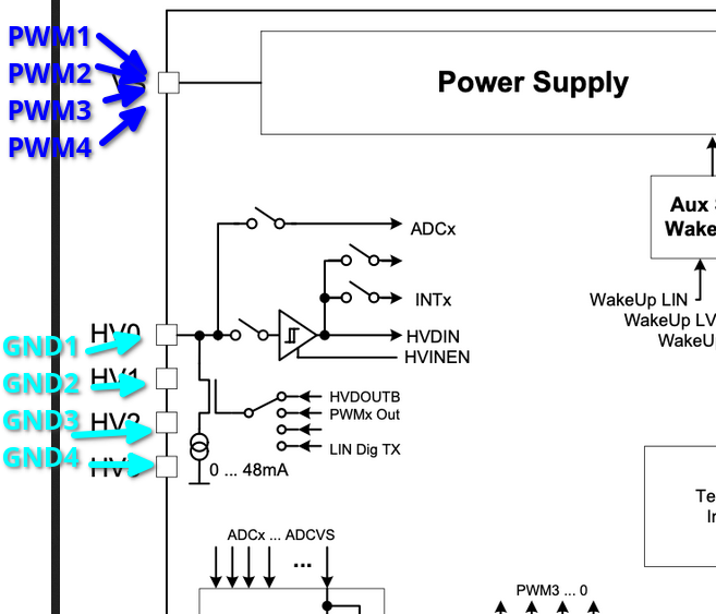
Ausschnitt eines Blockschaltbilds oder Schaltplans
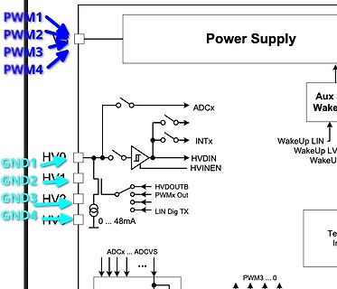
PWM1 PWM2 PWM3 PWM4 Power Supply ADCx INTx HVDIN HVINEN HVDOUTB PWMx Out LIN Dig TX WakeUp LIN WakeUp LV WakeU GND1 GND2 GND3 GND4 HV 0 ... 48mA ADCx ... ADCVS PWM3 ... 0
in „RGB Verstärker/Amplifier PWM gesucht“ · Mikrocontroller und Digitale Elektronik · · Diagramme
-
Datei
Zeitschalter.bas
Legen $end Asm On Timer0 Ontimer0 Config Timer0 = Timer , Prescale = 256 Enable Timer0 Config Timer1 = Pwm , Pwm = 9 , Prescale = 64 , Compare A Pwm = Clear Down , Compare B Pwm = Clear Down Enable Timer1 ' ----- Startbedingungen einstellen Tcnt0 = Timerwert 'Vorwert für Timer0 einstellen Led = 0 Zeit1 =
in „Programm umschreiben Mega8-Andruino“ · Mikrocontroller und Digitale Elektronik ·
-
Datei
isrs.S
// ISRs for FireFly project #include <avr/io.h> #define FLAG_WAVE 0 // PWM is active for a LED #define FLAG_TIMER 1 // PWM is active #define FLAG_UPDATE 2 // Watchdog signaled a update #define SIZEOF_FLY 12 // sizeof struct firefly_t #define WAVE_END_L 0 // offsets to members
in „Glühwürmchen in Rotkohlglas gefangen“ · Projekte & Code ·
-
PDF
IW1766.pdf
iW1766 Product Brief Ultra-Low No-Load Power Digital Quasi-Resonant PWM Controller 1.0 Features 2.0 Description ●● Ultra-low no-load power consumption with lowest The iW1766 is a high performance system cost (< 10mW at 230V in typical 5V/2A 10W AC/DC power supply controller which AC power supplies) uses digital control technology to build peak-current mode PWM flyback power ●● Fast dynamic response with secondary-side load transient detection supplies. The device operates in quasi-resonant mode to provide high efficiency along with a ●● Tight constant-voltage
in „Datenblatt für R1Y8K Schaltnetzteil IC gesucht“ · Analoge Elektronik und Schaltungstechnik ·
-
 Bild
Bild
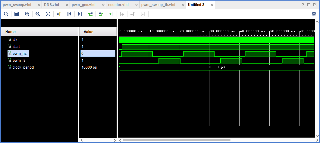
Simulation von PWM-Signalen in einer HDL-Software
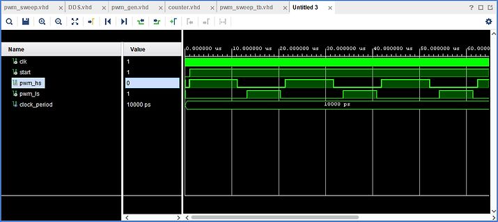
pwm_sweep.vhd, DDS.vhd, pwm_gen.vhd, counter.vhd, pwm_sweep_tb.vhd, Untitled 3, Name, Value, clk, 1, start, 1, pwm_hs, 0, pwm_ls, 1, clock_period, 10000 ps, 0.000000 us, 10.000000 us, 20.000000 us, 30.000000
in „Hochauflösende DC-Motor PWM / Sweep“ · FPGA, VHDL & Co. · · Screenshots
-
PDF
REV12schoen.pdf
3 F 2 1 D - 0 R6 0 18 VCC IC1 SHUNT 50mohm 2 2 PE-CASE oC ILD6150XUMA1 1 B l 1 2 1 8 e 2 EN TADJ 7 PWM VS C f 1 3 GND_1 VSENSE 6 V . 6 4 GND_2 VSWITCH 5 1 1 0 C PWM ) 1 C31 V 2 D 2 6 12V 5 G 2 u 5 HLK-PM03 c _ 1 . M D B l GND E R 4 2 S 1 3 E m c T 1 2 2 AC_1 -V0 4 J m 2 m 2 1 C24 mlcc 100V 4.7uF C16
in „Probleme mit Konstantstromtreiber / gatetreiber“ · Analoge Elektronik und Schaltungstechnik ·
-
PDF
8XCE558.pdf
gives the current reload value. The actual count of the prescaler cannot be read. 7 6 5 4 3 2 1 0 PWM0 (FCH) PWM0.7 PWM0.6 PWM0.5 PWM0.4 PWM0.3 PWM0.2 PWM0.1 PWM0.0 Figure 11. Pulse width register PWM0. Table 7. Description of PWM0 bits BIT FUNCTION (PWM0) PWM0.0 to 7 LOW/HIGH ration of PWM0 signal
in „Gesucht: schnelles 8051-Derivat mit Bootloader“ · Mikrocontroller und Digitale Elektronik ·
-
PDF
avr443.pdf
Figure 2-4. Figure 2-4. Driver circuit for the U, V and W motor coils (only U driver shown). Three PWM channels, OC0A, OC0B and OC2B, control the low side of the driver bridge (e.g. UL on Figure 2-4). This gives the possibility to control the current flow using hardware based PWMs with a minimum of timer resources in use. This controls the speed of the motor: by varying the duty cycle of the PWM output the current flow and thereby the speed (and torque) of the motor is controlled. It is also possible to have PWM based control of the high side of the bridge, but that would require all the ATmega48
in „Verstädnisfrage zu einer MOSFET Schaltung“ · Mikrocontroller und Digitale Elektronik ·
-
PDF
SC51P66E04_Datasheet_1.20190628115453636973.pdf
Timers (T0/T1), compatible with traditional MCS51, T0 supports square wave output while T1 supports PWM output 12-bit universal pulse generator (UPG), supporting 8+4 precision expansion and 2-channel complementary PWM output One 4-channel 12-bit ADC, sample rate is up to 200ksps 1-channel UART
in „Welche IC's / Funktion Mittelabgriff Akkupack ?“ · Analoge Elektronik und Schaltungstechnik ·
-
PDF
Frequenzrechner_neu.pdf
grafisch dargestellt PWM Takt mit Frequenz (Hz) 100 Hz x 256 = 25641 Hz ~ 39 µs Timer zählt 0 312 Takte 255 ISR PWM Zähler = 0 0 . . 312 Takte . 255 ISR PWM Zählre = 127 PWM Periode 0 . 25641 Hz / 256 = 100,16 Hz . ~ 9,98 ms 312 Takte . 255 ISR PWM Zähler = 255
in „Frage zum Artikel "Soft PWM"“ · Mikrocontroller und Digitale Elektronik ·
-
Datei
18F4550.h
CCP_COMPARE_INT 0xA #define CCP_COMPARE_INT_AND_TOGGLE 0x2 #define CCP_COMPARE_RESET_TIMER 0xB #define CCP_PWM 0xC #define CCP_PWM_PLUS_1 0x1c #define CCP_PWM_PLUS_2 0x2c #define CCP_PWM_PLUS_3 0x3c //#define CCP_USE_TIMER3 0x100 OBSOLETE, SEE TIMER-3 #word CCP_1 = getenv("SFR:CCPR1L") #byte CCP_1_LOW = getenv
in „Unknown keyword in #FUSES "INTRC"“ · Mikrocontroller und Digitale Elektronik ·
-
PDF
AP3019A-318144-1.pdf
Figure 18. Typical Application Circuit to Decide R1 (1) Adding a Control Signal to CTRL Pin Adding a PWM Signal to CTRL pin directly. The LED Current Control Refer to Figure 18, the LED current is controlled by AP3019A is turned on or off by the PWM signal the feedback resistor R1. LEDs' current accuracy
in „StepUp Regler mit wenig Aussenbeschaltung“ · Analoge Elektronik und Schaltungstechnik ·
-
 Bild
Bild
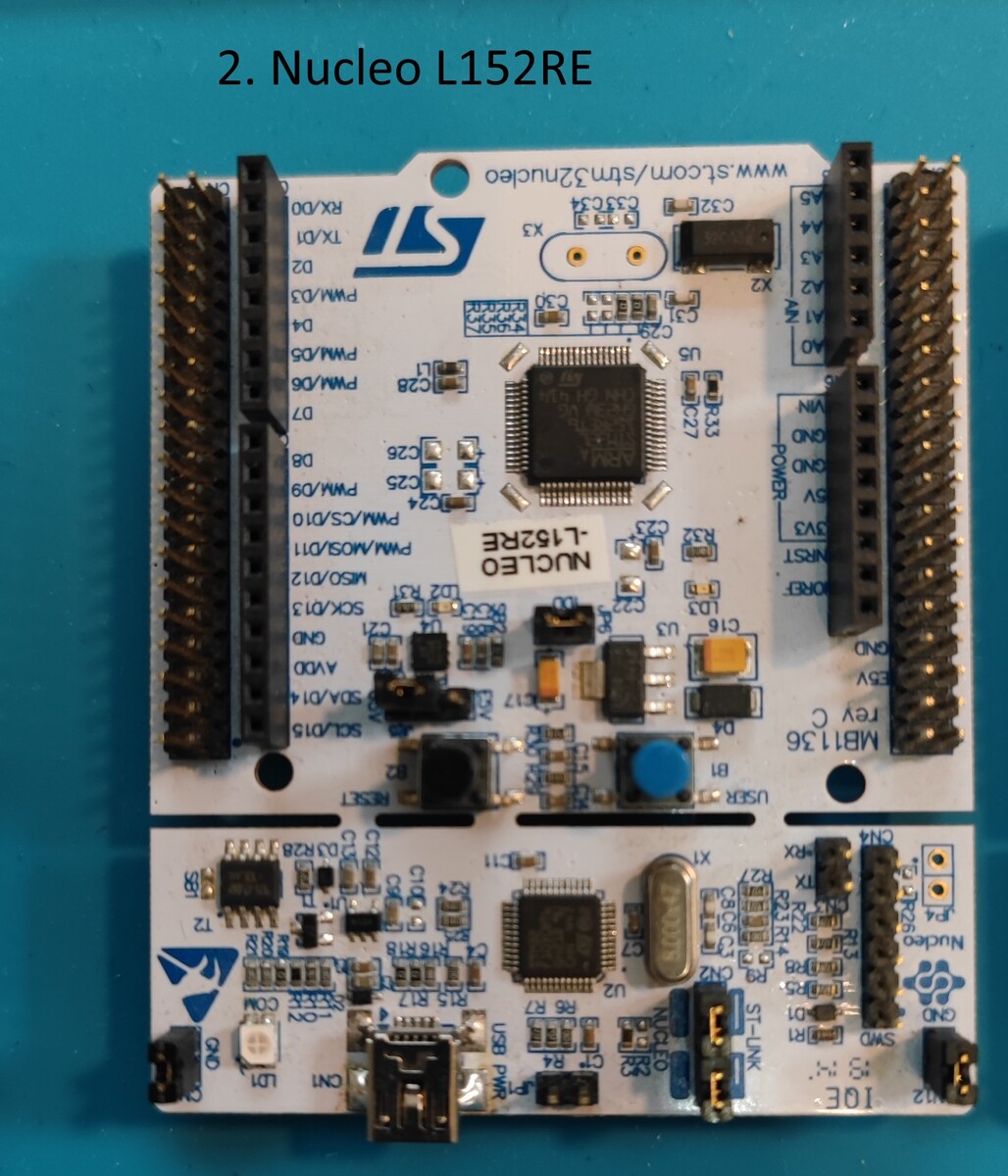
ST Nucleo-L152RE Mikrocontroller-Entwicklungsboard
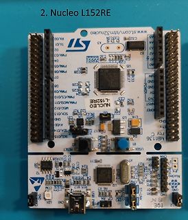
2. Nucleo L152RE ST www.st.com/strn32nucleo TX/D1 D2 PWM/D3 D4 PWM/D5 D6 PWM/D6 D7 PWM/D9 D8 PWM/D10 CS/D11 MSD/D12 SCL/D13 SDA/D14 QND/D15 AVDD SCL/D15 RESET USB PWR ST-LINK MB1136 USER NUCLEO-L152RE
in „[V] Sammlung diverser Entwicklungsboards“ · Markt · · Platinenfotos
-
Datei
timercounter.asm
0<<TOIE1) ;INT für ICP=off, OCIE1A=off, OCIE1B=off, OVFL=1 out TIMSK,temp0 ret mode5_T1_init:;FAST PWM 8bit OCR1A h:l,OCR1B h:l update ocrxH:L on bottom oder im INT ;rcall A_ch_en ;out aktivieren ;rcall B_ch_en ;out aktivieren ;rcall A_ch_load ;Zeitwert laden ;rcall B_ch_load ;Zeitwert laden ldi temp0
in „Atmel Studio 6.1 vs. 4.18“ · Mikrocontroller und Digitale Elektronik ·
-
PDF
AL5801.pdf
11 AL5801 July 2012 Document number: DS35555 Rev. 3 - 2 www.diodes.com © Diodes Incorporated AL5801 PWM Dimming (a) (b) Figure 16 Application Circuits for LED Driver with PWM Dimming Functionality (a) MOSFET driving and (b) Transistor driving PWM dimming can be achieved by driving the BIAS pin (1). An
in „Suche Konstantstromquelle effizient, klein und günstig.“ · Analoge Elektronik und Schaltungstechnik ·
-
 Bild
Bild
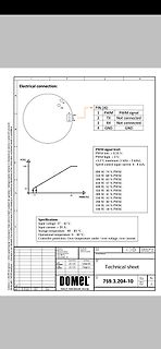
Technisches Datenblatt eines DOMEL Reglers
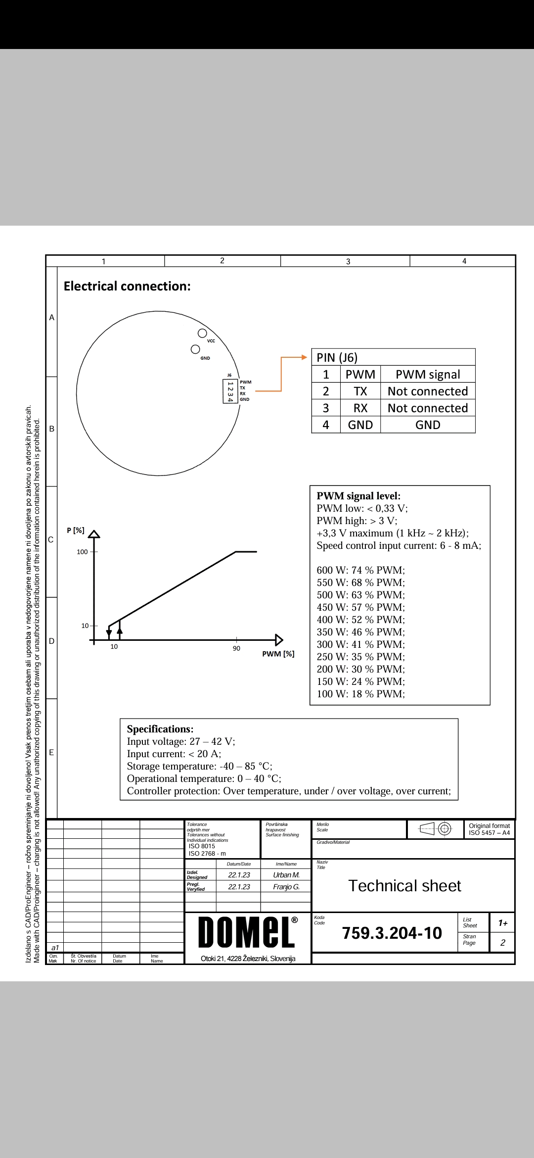
Electrical connection: PIN (J6) 1 PWM PWM signal 2 TX Not connected 3 RX Not connected 4 GND GND PWM signal level: PWM low: < 0,33 V; PWM high: > 3 V; Specifications: Input voltage: 27 - 42 V; Input current: < 20 A; Storage temperature:
in „Brushles motor steuerung pwn TX RX GND“ · Analoge Elektronik und Schaltungstechnik · · Screenshots