-
Datei
M16_TWI.c
/* TWI Test ATMega16 Quarz 8MHz LCD an PortC[2..7] und PortD7 PCF8574P: A[0..2] an Vcc 8x Low_Current LED; Port=>Masse Interne Pullups für TWI LCD_Backlight geschaltet über PORTA0 */ #ifndef F_CPU #define F_CPU 8000000UL
in „AVR Problem mit TWI / PCF8574P“ · Mikrocontroller und Digitale Elektronik ·
-
Datei
benchtest.txt
Compiler: riscv-none-elf-gcc Version 14.2.0 / ch32v003fun Framework | Zeit [s] | Optimierung | int8 | int16 | int32 | float | Codegroesse | ---------------------------------------------------------------------------- -Os | 7,8 | 7,7 | 28,8 | 2,52 | 5692 | -------------------------------------------
in „CH32V003, float wirklich langsam?“ · Mikrocontroller und Digitale Elektronik ·
-
Datei
main.c
// Atmega328p intern 1 Mhz #define F_CPU 1000000UL #include <avr/io.h> #include <util/delay.h> #include <avr/interrupt.h> // #include <avr/power.h> #include <avr/sleep.h> #include "rfm69.c" uint8_t array[MAX_ARRAYSIZE + 1]; uint8_t tx_length; volatile uint8_t sekunden=0; void watchdog_init() { // watchdog konfigurieren WDTCSR = (1 << WDCE)|(1 << WDE); // zunaechst Schutz des Registers aufheben gemaess Datasheet WDTCSR = (1 <<
in „Atmega328p in Sleep und mit Watchdog wecken“ · Mikrocontroller und Digitale Elektronik ·
-
Datei
lcd.h
to buffer #if defined GRAPHICMODE void lcd_drawPixel(uint8_t x, uint8_t y, uint8_t color); void lcd_drawLine(uint8_t x1, uint8_t y1, uint8_t x2, uint8_t y2, uint8_t color); void lcd_drawRect(uint8_t px1, uint8_t py1, uint8_t px2, uint8_t py2, uint8_t color); void lcd_fillRect(uint8_t px1, uint8_t py1, uint8_t px2, uint8_t py2, uint8_t color); void lcd_drawCircle(uint8_t center_x, uint8_t center_y, uint8_t radius, uint8_t color); void lcd_fillCircle(uint8_t center_x, uint8_t center_y
in „SSD1306/1309 Library zum Darstellen von Text auf OLED Displays“ · Projekte & Code ·
-
 Bild
Bild
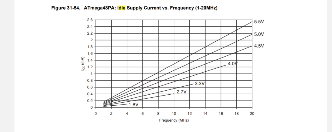
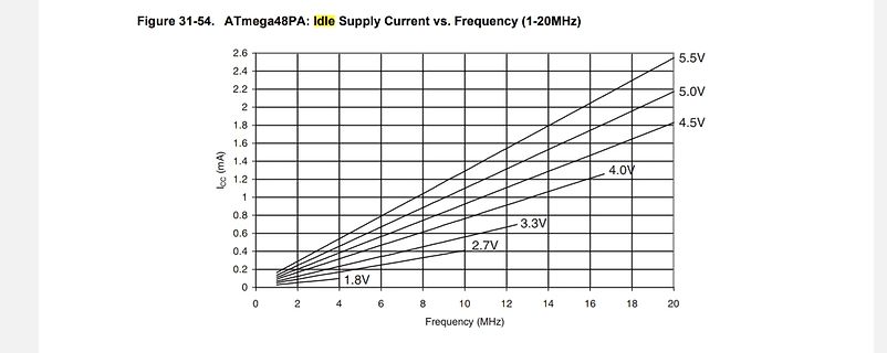
Diagramm des ATmega48PA Idle Supply Current vs. Frequency
Figure 31-54. ATmega48PA Idle Supply Current vs. Frequency (1-20MHz) 2.6 2.4 2.2 2 1.8 1.6 1.4 1.2 1 0.8 0.6 0.4 0.2 0 ICC (mA) 5.5V 5.0V 4.5V 4.0V 3.3V 2.7V 1.8V 0 2 4 6 8 10 12 14 16 18 20 Frequency (MHz)
in „Schaltung Messung kleiner Ströme bei uC in Standby/Idle“ · Analoge Elektronik und Schaltungstechnik · · Screenshots
-
Datei
Test.c
properly (don't forget to also ** connect GND between Master and Slave!) ** ** Used uC for Slave is ATMega8 */ int main (void) { uint8_t i=0; uint8_t j=0; uint8_t byte[8]; uint8_t TWIS_ResonseType; lcd_init(); // Clear any interrupt cli (); // Wait 1 second for POR _delay_ms(500); // Initiate RS232 print
in „AVR TWI Master und Slave Funtionen in C“ · Projekte & Code ·
-
Datei
RFM02.c
/**************************************************************************** * Pinbelegung: * ATMEGA8 RFM02 * ----------------------- * SCK (PB5) SCK * PB4 FSK * MOSI (PB3) SDI * SS (PB2) nSEL * PB1 nIRQ *****************************************************************************/ #include <avr/io.h
in „Problem mit RFM01/RFM02“ · Mikrocontroller und Digitale Elektronik ·
-
Datei
main.c
<avr/interrupt.h> #include "HD44780.c" #define XTAL 8e6 // 8MHz #define ENCODER_PIN PINC #define PHASE_A (1<<PC1) #define PHASE_B (1<<PC3) // #define LEDS_DDR DDRB // #define LEDS PORTB // LEDs against VCC volatile int8_t enc_delta; // -128 ... 127 static
-
Datei
main.c
<avr/interrupt.h> #include "HD44780.c" #define XTAL 8e6 // 8MHz #define ENCODER_PIN PINC #define PHASE_A (1<<PC1) #define PHASE_B (1<<PC3) // #define LEDS_DDR DDRB // #define LEDS PORTB // LEDs against VCC volatile int8_t enc_delta; // -128 ... 127 static
-
PDF
RN-Mega_Board.pdf
konzipiert die bereits Erfahrungen mit AVR-Controllern haben oder denen die kleineren AVR´s wie Mega8/Mega32 oder Mega128 noch nicht ganz ausreichen bzw. zu wenig Reserven bieten. Dieses Modul nutzt den neusten Controllerchip ATMega2560. Er dürfte derzeit ohne Frage einer der leistungsfähigsten AVR Controller
in „ATmega2560 spinnt“ · Mikrocontroller und Digitale Elektronik ·
-
Datei
Uhr.c
//ATmega8 //Header Dateien #include <avr/io.h> #include <avr/interrupt.h> #define TIMER2_COMP_vect _VECTOR(3) #include <util/delay.h> #define F_CPU 8000000UL ///////////// //Variablen// ///////////// volatile uint8_t a; volatile uint8_t b; volatile uint8_t c; volatile uint8_t d; volatile uint8_t e; volatile uint8_t f; volatile uint8_t g; volatile uint8_t h; volatile uint8_t neuse; volatile uint8_t neuse; volatile
in „Selbstlaufende Uhr mit AVR Atmega8“ · Mikrocontroller und Digitale Elektronik ·
-
Datei
adc_test_001.c
/*Analog-Digital-Converter (ADC) ATmega32 @ 8 Mhz (c) Christoph Anlauf 3AN ************************************************ Spannungsrefernz über AREF Am PINA0 wird die Spannung gemessen ************************************************ *
in „ADC/RS232 mit ATmega32“ · Mikrocontroller und Digitale Elektronik ·
-
Datei
main.c
include <util/delay.h> #include "uart.h" #include "rfm70.h" #define UART_BAUD_RATE 9600 volatile uint8_t interruptFlag = 0; //Varible die beim auslösen des INT0 Interrupts verändert wird, 1=Interrupt ausgelöst ISR(INT0_vect) { //Interrupt am ATMega wird ausgelöst interruptFlag = 1; //Wechsel des Status } int main() { cli(); //Interrupt deaktivieren uint8_t buffer[32]; //Array zum speichern der empfangenen Daten uint8_t tmpRegister; //Varibale zur Speicherung beliebiger Registerwerte uint8_t lenPayload; //Variable zur Speicherung der Länge des empfangegen
in „RFM70 Timing Problem?“ · Mikrocontroller und Digitale Elektronik ·
-
Datei
regelung.c
// Timer0 gesteuerter AD-Wandler mit anschl. Berechnungen // // Atmega16 16MHz Takt // AD-Wandlerkanal ADC0, Bereich 0-5V, 8-bit // Ausgabe binär am PortC (für R/2R Netzwerk) // // Timer0 soll jedesmal bei Overflow (jede 128us) den AD-Wandler für eine Einzelwandlung zünden
in „Timer0 gesteuerter AD-Wandler“ · Mikrocontroller und Digitale Elektronik ·
-
Datei
regelung.c
// Timer0 gesteuerter AD-Wandler mit anschl. Berechnungen // // Atmega16 16MHz Takt // AD-Wandlerkanal ADC0, Bereich 0-5V, 8-bit // Ausgabe binär am PortC (für R/2R Netzwerk) // // Timer0 soll jedesmal bei Overflow (jede 128us) den AD-Wandler für eine Einzelwandlung zünden
in „Timer0 gesteuerter AD-Wandler“ · Mikrocontroller und Digitale Elektronik ·
-
Datei
global.h
------------------- #ifndef EXTERN #define EXTERN extern #endif #define M168 // Register für den ATMEGA168 //#define M8 #define WATCHDOG #define LOG_RS232 // Log-Datei auf RS232 ausgeben #define LCD // ohne LCD Ausgaben ist der Code 1250 Byte kürzer #define DEBUG // lässt den Fehlercounter im LCD stehen
in „DCF-Uhr, Sonnenstand, TWI-Port, Alarmfunktion für m8 in C“ · Projekte & Code ·
-
Datei
uart.c
#ifdef __AVR_ATmegaM32__ UCSRC |= ( 1 << URSEL )|(1 << UCSZ1)|(1 << UCSZ0); // Asynchron 8N1 #else UCSRC |= (1 << UCSZ1)|(1 << UCSZ0); // Asynchron 8N1 #endif UBRRH = (uint8_t) (UART_UBRR_BAUD>>8); UBRRL = (uint8_t) (
in „UART von Mega32 auf Mega168 anpassen“ · Mikrocontroller und Digitale Elektronik ·
-
Datei
main.c
gmail.com) * **********************************************************/ /* This file is modified for ATMega16 with more than 8 shift registers for use in my 9x9x9 LED CUBE */ #include <avr/io.h> #include <avr/interrupt.h> #include <util/delay.h> #define SHIFTBITS 88 #define SER PB3 #define RCK PB2 #define
in „uint128_t mit AVR?“ · Mikrocontroller und Digitale Elektronik ·
-
PDF
schaltung.pdf
MAX232 5 + 0 + 1 C1+ C +5V 6 5 C V+ 2 + 1 C+ C11 3 C1- 6 + D V 100n + 4 V- N MAX232P 1 ATMEGA640P C2+ C G N 2 39 C 5 X1 1 G R1 3 38 C2- 1 4 37 11 14 2 6 V 10k 5 36 10 T1IN T1OUT 7 3 7 GND 5 C12 6 35 12 T2IN T2OUT 13 4 8 8C+ C1 7 34 C7 9 R1OUT R1IN 8 5 9 V 100n 8 33 R2OUT R2IN IC1P 100n F 9
in „Datenübertragung über UART zu 2xSMCi33-2 von Nanotec“ · Mikrocontroller und Digitale Elektronik ·
-
PDF
schaltung.pdf
MAX232 5 + 0 + 1 C1+ C +5V 6 5 C V+ 2 + 1 C+ C11 3 C1- 6 + D V 100n + 4 V- N MAX232P 1 ATMEGA640P C2+ C G N 2 39 C 5 X1 1 G R1 3 38 C2- 1 4 37 11 14 2 6 V 10k 5 36 10 T1IN T1OUT 7 3 7 GND 5 C12 6 35 12 T2IN T2OUT 13 4 8 8C+ C1 7 34 C7 9 R1OUT R1IN 8 5 9 V 100n 8 33 R2OUT R2IN IC1P 100n F 9
in „Datenübertragung über USART0 und USART1“ · Mikrocontroller und Digitale Elektronik ·
-
PDF
GMS328.pdf
-12 R10 Q2 GND 7 PD4 PC0 22 C122P 1 8 VCC GND 21 GND 27K C945 R9 z 9 GND AREF 20 3K3 X1 M 10 PB6 AVCC 19 D1 8 PB7 PB5 LED 2 11 PD5 PB4 18 GND U1-12 12 PD6 PB3 17 GND C2 U1-13 13 PD7 PB2 16 22P 14 PB0 PB1 15 C945 Q3 U1 ATMEGA328P 5 4 U1-13 K1 R R K R C 8 0 8 7 8 0 R15 C 6 4 6 4 6 4 27K 1 2 3 4 5 6 3 J1 R22 C9 R R R R R R T TL431A R17 1 3 1 5VCC 2 2 2K2 470R 104 T GND 1 2 3 1 R24 R23 T U3 C3 Net 2 Net 1 104 10K 10K GND V GND GND R 3 2 1 2 3 2 1 J2 0 3
in „neuer Transistortester GM328 aus China“ · Analoge Elektronik und Schaltungstechnik ·
-
PDF
4660.pdf
-12 R10 Q2 GND 7 PD4 PC0 22 C122P 1 8 VCC GND 21 GND 27K C945 R9 z 9 GND AREF 20 3K3 X1 M 10 PB6 AVCC 19 D1 8 PB7 PB5 LED 2 11 PD5 PB4 18 GND U1-12 12 PD6 PB3 17 GND C2 U1-13 13 PD7 PB2 16 22P 14 PB0 PB1 15 C945 Q3 U1 ATMEGA328P 5 4 U1-13 K1 R R K R C 8 0 8 7 8 0 R15 C 6 4 6 4 6 4 27K 1 2 3 4 5 6 3 J1 R22 C9 R R R R R R T TL431A R17 1 3 1 5VCC 2 2 2K2 470R 104 T GND 1 2 3 1 R24 R23 T U3 C3 Net 2 Net 1 104 10K 10K GND V GND GND R 3 2 1 2 3 2 1 J2 0 3
-
Datei
ADC_DKB.txt
************************ * * Function name : ADC_conversion * * Returns : unsigned int adc result, 8 x averaged * * Parameters : None * * Purpose : Run the ADC conversion on ATMEGA16 * ******************************************************************************************/ unsigned int ADC_conversion
in „ADC-Ergebnis immer rund +35 AD-Werte zu hoch“ · Mikrocontroller und Digitale Elektronik ·
-
 Bild
Bild
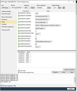
Software zur AVR-Mikrocontroller-Programmierung
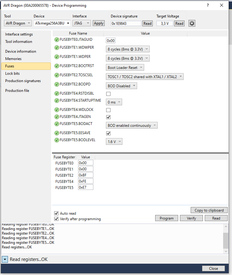
AVR Dragon (00A200065578) - Device Programming Tool Device Interface Apply AVR Dragon ATmega256A3BU JTAG Device signature 0x1E9843 Read Target Voltage 3,3 V Read Interface settings Fuse Name Value Tool information FUSEBYTE0.JTAGUID 0x00 Device information FUSEBYTE1.WDPR 8 cycles (8ms @ 3.3V) Memories FUSEBYTE1.WDPR 8 cycles (8ms @ 3.3V) Fuses FUSEBYTE2.BOOTRST Boot Loader Reset Lock bits FUSEBYTE2.TOSCSEL TOSC1 / TOSC2 shared with XTAL1 / XTAL2 Production signatures FUSEBYTE2.BODPD BOD Disabled Production file FUSEBYTE4
in „Software von Atmel xmegaA3BU runterladen“ · Mikrocontroller und Digitale Elektronik · · Screenshots
-
Datei
ENCODE2.C
********************/ #include <avr/io.h> #include <avr/interrupt.h> // target: ATtiny2313 ( was ATmega16 in original ) //------------------------------------------------------------------------ #define XTAL 8e6 // 8MHz #define PHASE_A (PIND & 1<<PD0) #define PHASE_B (PIND & 1<<PD1) #define LEDS_DDR
in „Drehgeber/Encoder 1-, 2- oder 4-schrittig“ · Projekte & Code ·
-
Datei
ENCODE2.C
********************/ #include <avr/io.h> #include <avr/interrupt.h> // target: ATtiny2313 ( was ATmega16 in original ) //------------------------------------------------------------------------ #define XTAL 8e6 // 8MHz #define PHASE_A (PIND & 1<<PD0) #define PHASE_B (PIND & 1<<PD1) #define LEDS_DDR
in „Drehgeber/Encoder 1-, 2- oder 4-schrittig“ · Projekte & Code ·
-
Datei
oled.h
command to display void oled_command(uint8_t cmd); // transmit data to display void oled_data(uint8_t data); // set curser at pos x, y. x means character, y means line // (page, refer oled manual) void oled_gotoxy(uint8_t x, uint8_t y); // clear
in „SSD1306/1309 Library zum Darstellen von Text auf OLED Displays“ · Projekte & Code ·
-
 Bild
Bild
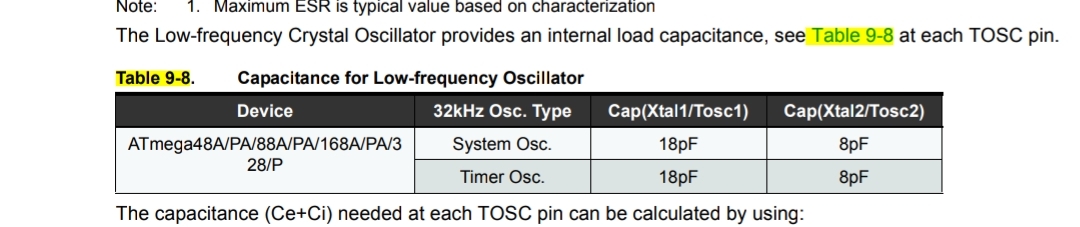
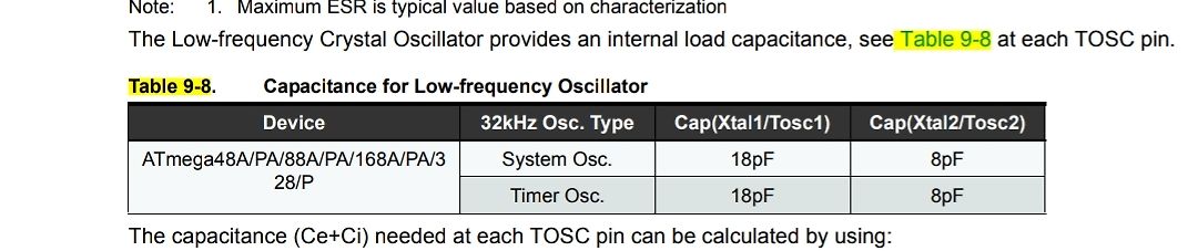
Tabellenausschnitt aus einem Datenblatt für Mikrocontroller
characterization The Low-frequency Crystal Oscillator provides an internal load capacitance, see Table 9-8 at each TOSC pin. Table 9-8. Capacitance for Low-frequency Oscillator Device | 32kHz Osc. Type | Cap(Xtal1/Tosc1) | Cap(Xtal2/Tosc2) ATmega48A/PA/88A/PA/168A/PA/328/P | System Osc. | 18pF | 8pF | Timer Osc. | 18pF | 8pF The capacitance (Ce+Ci) needed at each TOSC pin can be calculated by using:
in „Schaltung Messung kleiner Ströme bei uC in Standby/Idle“ · Analoge Elektronik und Schaltungstechnik · · Screenshots
-
 Bild
Bild
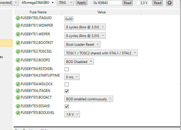
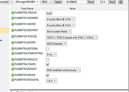
Software-Ansicht der Fuse-Einstellungen eines ATmega-Mikrocontrollers
ATmega256A3BU JTAG Apply 0x1E9843 Read 3,3 V Read Fuse Name Value FUSEBYTE0.JTAGUID 0x00 FUSEBYTE1.WDWPER 8 cycles (8ms @ 3.3V) FUSEBYTE1.WDPER 8 cycles (8ms @ 3.3V) FUSEBYTE2.BOOTRST Boot Loader Reset FUSEBYTE2
in „LED toggeln mit ATxmega256A3BU“ · Mikrocontroller und Digitale Elektronik · · Screenshots
-
Datei
Sketch.txt
/* Test Garagentor ATMega328p I2C-Display mit Backpack-Modul Saintsmart, Funduino u.a. 20x4 Display NewLiquidCrystal_I2C Library verwendet, Orig. LiquidCrystal_I2C und LiquidCrystal in anderen Ordner verschieben oder löschen! (Vorher sichern.) */ #include <Wire.h> #include <LiquidCrystal_I2C.h> // (uint8_t lcd_Addr, uint8_t En, uint8_t Rw, uint8_t Rs, uint8_t d4, uint8_t d5, uint8_t d6, uint8_t d7, uint8_t backlighPin, t_backlighPol pol) LiquidCrystal_I2C lcd(0x20,2,1,0,4,5,6,7,3,POSITIVE); // Funduino
in „Stromflussabbruch mit Arduino Nano steuern?“ · Mikrocontroller und Digitale Elektronik ·
-
PDF
Schaltung.pdf
Sättigung von (h_FE)/(3.3 )= 50 * Daraus folgt: I_b=(300mA \60 = 6mA * Der Mikrocontroller sei vom Typ ATmega oder ATtiny und liefert bei einer Versorgungsspannung von 5V abzüglich 5% Toleranz mindestens 4,5 Volt bei 6mA. Weiter fallen 0,7 V an der BE-Strecke ab, also bleiben ca. 3,8 V. * Rb = 3,8V/6mA=633 Ohm Rb=500 Ohm 3,8V*6mA=0,0228W Metallschichtwiderstand 499 Ohm 1/4W 1%
in „uC + 3 Schieberegister + 7-Segmentanzeige“ · Mikrocontroller und Digitale Elektronik ·
-
Datei
Sketch.txt
/ /* one, two and four step encoders supported */ /* */ /* Author: Peter Dannegger */ /* target: ATmega16 */ /************************************************************************/ #include <avr/io.h> #include <avr/interrupt.h> //#define XTAL 8e6 // 8MHz #define F_TIMER1 100 // Timer 1 frequency /
in „Peter Dannegger´s ( PeDa ) Entprellroutine in ein Arduino Sketch einbinden“ · Mikrocontroller und Digitale Elektronik ·
-
Datei
Example1_DisplayTest.ino
myTOLED.xExt/2, true); } #if !defined(__AVR_ATmega328P__) && !defined(__AVR_ATmega168__) void showLogo( void ){ myTOLED.setContrastControl(0); myTOLED.pixelSet(84, 3); myTOLED.pixelSet(85, 3); myTOLED.pixelSet(86, 3); myTOLED.pixelSet(87, 3); myTOLED.pixelSet
in „Arduino OLED Display Ansteuern & "Hello World" Programme gehen nicht.“ · Softwareentwicklung ·
-
Datei
test2.c
/* Eine 8-kanalige PWM mit verbessertem Lösungsansatz ATmega32 @ 8 MHz */ // Defines an den Controller und die Anwendung anpassen #define F_CPU 16000000L // Systemtakt in Hz #define F_PWM 100 // PWM-Frequenz in
in „Moodlight Sourcecode hilfe“ · Mikrocontroller und Digitale Elektronik ·
-
Datei
Laufschrift_04_Test_Fehler_Reset.ino
************************ * 0.96" Display (160x80px) ansteuern * Controller: ST7735S * 13pol. PFC 0.8mm Display Typ: RFA300960A-AYW-DNN * 8pol. PFC 0.5mm * * Einstellungen IDE: Board: "Arduino Pro or Pro Mini" * Processor: "ATmega328P (5V, 16MHz)" * Programmer: "AVRISP mkII" * * Einstellungen serielle Schnittstelle: 9600 Baud, 8N1 * * Anschluss: * D8: -> RS * D9: -> RST * D10: SS -> CS * D11: MOSI -> SDA * D13: SCK -> SCL * * PFC: Display Anschlüsse: * 1 SPI4W SPI4W=’0’, 3-wire SPI. SPI4W=’1’, 4-wire SPI. * 2 NC No connection
in „ATmega328P resettet bei I/O Zugriff“ · Mikrocontroller und Digitale Elektronik ·
-
Datei
H_Encoder_PeDA_ATmega2560__C_net.txt
/ /* one, two and four step encoders supported */ /* */ /* Author: Peter Dannegger */ /* target: ATmega16 */ /************************************************************************/ #include <avr/io.h> #include <avr/interrupt.h> //#define XTAL 8e6 // 8MHz #define F_TIMER1 100 // Timer 1 frequency /
in „Peter Dannegger´s ( PeDa ) Entprellroutine in ein Arduino Sketch einbinden“ · Mikrocontroller und Digitale Elektronik ·
-
Datei
Code.txt
//////////////////////////// //Diplomarbeit Hexapod: //for Win32.Devbug //Microcontroller: Atmel ATMEGA 8-16PU (8MHz Interner Oszillator) //Programmierer: Ralph Ankele //Programmiersprache: C //Title: hexapod_AEM_board.c //Datum 10.02.2009 //Version 1.0 ///////////////////////////////////////////////
in „usart strings senden problem“ · Mikrocontroller und Digitale Elektronik ·
-
Datei
master.txt
// Master ATmega128 #include <avr/io.h> #include <stdint.h> #include <avr/interrupt.h> #ifndef F_CPU //#warning "F_CPU war noch nicht definiert, wird nun nachgeholt mit 4000000" #define F_CPU 8000000L // Systemtakt
in „Problem: SPI daten von mehreren slaves zum master! aber wie?“ · Mikrocontroller und Digitale Elektronik ·
-
PDF
Magazin_Bauteile.pdf
3,3V 300mA LDO Microchip Farnell 251-0377 0,142 0,43 4 5 5 3 DC-DC Wandler MAX653CPA+ 5V -> 3V 225mA 8-DIP Analog Devices Farnell 279-9237 3,300 9,90 X 4 6 1 4 Mikrocontroller ATMEGA644P-20PU DIP40 Microchip Farnell 145-5122 6,490 25,96 3 Mikrocontroller ATMEGA644P-20PU SMD Microchip Farnell 145-5121 6,230 18,69 2 Mikrocontroller ATMEGA1284-AU SMD Microchip Farnell 197-2064 5,440 10,88 4 6 2 2 I2C Bus Repeater PCA9517ADMR2G Onsemi Farnell 284-5092 0,845 1,69 X 4 6 3 1 2 RS485 LTC490CN8#PBF Analog Devices Farnell 402-4359 9,900 19,80
-
Datei
ds1820.h
* limitations under the License. * * * @purpose DS1820 Temperature Sensor Minimal interface for Atmega microcontrollers * http://www.pocketmagic.net/ */ /********************************************* * CONFIGURE THE WORKING PIN *********************************************/ #pragma once #include <avr
in „ATMega8 - LED-Thermometer (DS18S20)“ · Mikrocontroller und Digitale Elektronik ·
-
PDF
Belegung_Controllter_Bordcomputer.pdf
4 P 25 PC2 LCD (D6) Durchflussmesser PD3 5 6 24 PC1 LCD (D5) PD4 6 - 23 PC0 LCD (D4) Plus 5V VCC 7 8 22 AGND a Masse GND 8 g 21 AREF Takt extern PB6 9 e 20 AVCC Takt extern PB7 10 t 19 PB5 SCK (PC) PD5 11 A 18 PB4 MISO (PC) PD6 12 17 PB3 MOSI (PC) PD7 13 16 PB2 Taster 1 PB0 14 15 PB1 Taster 2 Seite
in „Durchflussmessung mit ATMEGA8“ · Mikrocontroller und Digitale Elektronik ·
-
Datei
Wegmessung3.bas
$regfile = "m8def.dat" 'Kenndaten für ATmega8 $crystal = 8000000 'Taktzahl des MC in Hz $baud = 19200 'Definiert die Übertragungsgeschwindigkeit Config Spi = Soft , Din = Pinc.1 , Dout = Pinc.3 , Ss = Portc.0 , Clock
in „Ansteuern eines Agilent Chip über das SPI Protokoll“ · Mikrocontroller und Digitale Elektronik ·
-
Datei
uart.h
Fehler der Baudrate grösser 1% und damit zu hoch! #endif void uart_init(void) { UBRRH = UBRR_VAL >> 8; UBRRL = UBRR_VAL & 0xFF; UCSRC |= (1<<UCSZ1) | (1<<UCSZ0); // Asynchron 8N1 UCSRB |= (1<<TXEN) | (1<<RXEN); // UART TX und RX einschalten } // senden von einem 8bit-wert // bei neueren AVRs steht der Status in UCSRA/UCSR0A/UCSR1A, hier z.B. fuer ATmega16: void uart_putc(unsigned char c) { while (!(UCSRA & (1<<UDRE))); /* warten bis Senden moeglich */ UDR = c; /* sende Zeichen */ } /* Zeichen empfangen */ uint8_t uart_getc(void) { while (!(UCSRA &
in „[RFM12BP] UART funktioniert nicht“ · Mikrocontroller und Digitale Elektronik ·
-
PDF
SCHALTPLAN_AKKU_TESTER.pdf
BUZ11 15V 4 33µ 7 AKKU-FACH-0 Lüfter 4 LCD 10k D3 D2 D1 D0 E R/W RS Kont+ GND PC1 PD6 14 13 12 11 10 9 8 7 6 5 4 3 2 1 1 1,2V PD3 BUZ11 PB5 PB4 AKKU-FACH-1 Programmier-Adapter 4 1 5 10k PC2 8 7 6 5 4 3 1 0 9 8 7 6 5 1 1,2V 2 2 2 2 2 2 2 2 2 1 1 1 1 1 16 9 r 5 4 3 2 1 0 ) ) ) 5 4 3 2 1 a C C C C C C N E C B B B B B PD4 BUZ11 - ( ( ( ( ( ( G R V ( ( ( ( ( AKKU-FACH-2 i ( ( ( MAX232 4 m ATmega8-16 g ) ) ) ) ) ) ) ) ) ) ) ) ) ) - 6 0 1 2 3 4 C D 6 B D D D B I P P P P P P V N P P P P P P PC3 10k P ( ( ( ( ( ( ( ( ( 0 1 2 3 4 1 2 3 4 5 6 7 8 9 1 1 1 1 1 1 8 1 1,2V 100nF 1µ PD5 BUZ11 16MHz 1µ
in „Einstellbare Konstantstromsenke für Akkuentladegerät“ · Mikrocontroller und Digitale Elektronik ·
-
Datei
SRAM_Ansprache.asm
;SRAM adressing, buffer setup example: ;(c) frei nach Schnauze 01-29-2018 ;.... ;ATmega32U2 memory use summary [bytes]: ;Segment Begin End Code Data Used Size Use% ;[.cseg] 0x000000 0x00002e 46 0 46 32768 0.1% ;[.dseg] 0x000100 0x000108 0 8 8 1024 0.8% ;[.eseg] 0x000000 0x000000 0 0 0
in „AVR Assembler relative jump“ · Mikrocontroller und Digitale Elektronik ·
-
Datei
Header_A400_BS.h
****************************************************** ;* ;*Titel: AVR-Kurs A400 ;* ;*Prozessor: ATmega8 Quarzfrequenz: intern 1Mhz ( DEFAULT ) ;* ;*Funktionsweise: ;* ;* Die Werkzeugmaschinen 8, 7 und 2 aus dem vorigen Beispiel wurden ;* eingeschaltet. Dies soll jetzt im Register r20 dokumentiert werden
in „AVR-Mikrocontrollertechnik-Kursus in Assembler besprechung“ · Mikrocontroller und Digitale Elektronik ·
-
Datei
m644def.inc
" ;* Title : Register/Bit Definitions for the ATmega644 ;* Date : 2007-02-28 ;* Version : 2.24 ;* Support E-mail : avr@atmel.com ;* Target MCU : ATmega644 ;* ;* DESCRIPTION ;* When including this file in the assembly program file, all I/O register ;*
in „AVR - Fehlermeldung beim Übersetzen von Assembler für ATmega644“ · Mikrocontroller und Digitale Elektronik ·
-
Datei
m644def.inc
" ;* Title : Register/Bit Definitions for the ATmega644 ;* Date : 2007-02-28 ;* Version : 2.24 ;* Support E-mail : avr@atmel.com ;* Target MCU : ATmega644 ;* ;* DESCRIPTION ;* When including this file in the assembly program file, all I/O register ;*
in „woher Registerdefinitionen für mega644?“ · Mikrocontroller und Digitale Elektronik ·
-
Datei
dmx_receive.c
/* This modul receives DMX512 data via * USART. * original target: ATmega8515 @8MHz * (for other devices please cahange pin & register definitions!) */ #include <inttypes.h> #include <avr/io.h> #include <avr/interrupt.h> #include <avr/signal.h> #define F_OSC 8000000 // Clock
in „USART-ISR mit mega8515“ · Mikrocontroller und Digitale Elektronik ·
-
Datei
TWI_Master_main.c
properly (don't forget to also ** connect GND between Master and Slave!) ** ** Used uC for Master is ATMega32 */ int main (void) { uint8_t i; uint8_t j=0; uint8_t Data[8]; uint8_t SlaveAddress = 15; /* ** Clear any interrupt */ cli (); /* ** Wait 1 second for POR */ lcd_init(LCD_DISP_ON); lcd_clrscr(); Delay_ms
in „AVR TWI Master und Slave Funtionen in C“ · Projekte & Code ·