
-
PDF
en.DM00096551.pdf
is the input offset voltage of the op-amp, has no importance in this application. The stage gain is 53.3 (Gain =11 + R /R 1. 2his amplification allows a usable signal that is higher than the noise level. The DC bias of the first architectural stage is determined by the sensor. To avoid saturation, the
in „D203S PIR mit ATMega 328 auslesen“ · Mikrocontroller und Digitale Elektronik ·
-
PDF
74HCT221__Nexperia.pdf
delay nA, nRD to nQ (trigger) VCC = 4.5 V - 30 50 - 63 - 75 ns V = 5 V; C = 15 pF - 36 - - - - - ns CC L nB to nQ (trigger) VCC = 4.5 V - 24 42 - 53 - 63 ns VCC = 5 V; CL= 15 pF - 36 - - - - - ns nRD to nQ (reset) VCC = 4.5 V - 31 51 - 64 - 77 ns VCC = 5 V; CL= 15 pF - 36 - - - - - ns 74HCT221 All information
in „Frequenz- bzw. Ton- Toff- Limiter bauen“ · Mikrocontroller und Digitale Elektronik ·
-
Datei
BMC_decrypt.txt
akivieren, Capture + Overflow } void uart_init(void) { UBRR0H = (unsigned char)(myBRR0 >> 8); UBRR0L = (unsigned char)myBRR0; UCSR0B = (1<<RXEN0)|(1<<TXEN0); //enablen RX und TX UCSR0C = (1<<USBS0)|(3<<UCSZ00); //8data, 2stopp } void uart_send(unsigned char data) { while (!(UCSR0A & (1<<UDRE0)) ); UDR0
in „Checksumme im Funkprotokoll von Thermo_Hygro-Sensor“ · Mikrocontroller und Digitale Elektronik ·
-
PDF
4415-0057_LNG_V1b.pdf
SENSE 2 2 R58 J5 470R R7 4 Safety Resistor -OUT 0R39/A, 5-10W R56 R55 -OUT B +15V V+ R54 B 100R 100R R53 82R 1K 7 7 U2C 7 c c 1 N1 c R14 R13 D7 V U3B V U1B RV1 V U2B Q51 1K5 10K 5V1 e C54 e C53 100K C52 e ZD51 2N3904 R2 e TL081 0u1 e TL081 0u1 NULL ADJ 0u1 e TL081 33V, 1W D5 C3 - - R10 - V+ 82R 1N4148 47uF
in „Labornetzgerät - Fragen zum Schaltplan“ · Analoge Elektronik und Schaltungstechnik ·
-
PDF
4415-0057_LNG_V1.pdf
SENSE 2 2 R58 J5 470R R7 4 Safety Resistor -OUT 0R47, 5W, W.W. R56 R55 -OUT B +15V V+ R54 B 100R 100R R53 82R 1K 7 7 U2C 7 c c 1 N1 c R14 R13 D7 V U3B V U1B RV1 V U2B Q51 1K5 10K 5V1 e C54 e C53 100K C52 e ZD51 2N3904 R2 e TL081 0u1 e TL081 0u1 NULL ADJ 0u1 e TL081 33V, 1W D5 C3 - - R10 - V+ 82R 1N4148 47uF
in „Labornetzgerät - Fragen zum Schaltplan“ · Analoge Elektronik und Schaltungstechnik ·
-
PDF
MX25L12835FM2I-10G.pdf
Mode 0 24-Bit Address Command SIO[3:0] 52h A5 A4 A3 A2 A1 A0 MSB P/N: PM1795 Rev. 1.6, July 22, 2016 53 M X 2 5 L 1 2 8 3 5 F 9-21. Block Erase (BE) The Block Erase (BE) instruction is for erasing the data of the chosen block to be "1". The instruction is used for 64K-byte block erase operation. A Write
in „FLASH Memory Chip im Lenovo X200 von 8 MB auf 16 MB vergroessern“ · PC Hard- und Software ·
-
PDF
ST7066U.pdf
S T Sitronix ST7066U Dot Matrix LCD Controller/Driver n Features l 5 x 8 and 5 x 11 dot matrix possible l 16-common x 40-segment liquid crystal l Low power operation support: display driver -- 2.7 to 5.5V l Programmable duty cycles l Wide range of LCD driver power -
in „LCD Zeichensatz wechseln?“ · Mikrocontroller und Digitale Elektronik ·
-
PDF
ST7066U.pdf
S T Sitronix ST7066U Dot Matrix LCD Controller/Driver n Features l 5 x 8 and 5 x 11 dot matrix possible l 16-common x 40-segment liquid crystal l Low power operation support: display driver -- 2.7 to 5.5V l Programmable duty cycles l Wide range of LCD driver power -
in „LCD- Das ewige Leiden“ · Mikrocontroller und Digitale Elektronik ·
-
PDF
FTS_BIOSHandbuchfuerSystemboardsmitIntel_R_7Series_1_1088598.PDF
Kompatibilität. Auto Maximale Energieeinsparung konfigurieren. Low-Power-Modus der PCI-Express-Verbindungen auf L0s (unidirektional) oder L1 (bidirektional) setzen. Limit to L0s Low-Power-Modus der PCI-Express-Verbindungen auf L0s (unidirektional) beschränken. Kompromiss zwischen Kompatibilität und Energieeinsparung
in „Bios Recovery Fehler D2990-a21“ · PC Hard- und Software ·
-
PDF
CMUcam2_manual.pdf
Historgram Configure 38 ST Set Track Command 52 HD High Resolution Difference 38 SV Servo Position 53 HR HiRes Mode 38 TC Track Color 53 HT Set Histogram Track 39 TI Track Inverted 53 L0 (1) Led Control 39 TW Track Window 54 LF Load Frame to Difference 39 UD Upload Difference buffer 55 VW Virtual Window
-
PDF
12_viver_2_190_600ec_3m576sv2f52.pdf
jest prądem jednofazowym. Parametry w punkcie pracy Parametry techniczne Wartości mocy akustycznej L WA [dB(A)] 3 Przepływ 100 m /h Hz Σ 63 125 250 500 1k 2k 4k 8k Ciśnienie statyczne 150 Pa Wlot - L 56 31 41 43 49 52 50 43 35 WA5 Pobór mocy 14 W Wylot - WA6 57 33 41 46 51 52 51 42 35 Napięcie nominalne ~1 230 V Poziom ciśnienia akustycznego L [dB(A)] Pobór prądu 0.23 A PA Odległość od wentylatora [m] L [dB(A)] Częstotliwość nominalna 50 Hz PA Prędkość obrotowa 1808 min -1 10,0 26 Prędkość przepływu 1.09 m/s 4,0 34 SFP 520 W/(m /s) 1,0 46
in „0-10V Steuerspannung für EC-Ventilatoren“ · Mikrocontroller und Digitale Elektronik ·
-
PDF
BB_Schem_75839_b.pdf
HDR1 COSC TG 0.1uF C4 2 15 TH3 RUN/SS BOOST 1 2 3 R2 10K C5 330pF HDR1 3 ITH SW 14 GND 2 C6 47pF 2 1 L1 R3 4 SFB VIN 13 10uH 0.02 TH4 D3 CMDSH C7 0.1uF 8 7 6 5 LED2 HDR1 5 12 1 GREEN LED GND SGND INTVCC C10 C8 C9 1 C11 100pF 4.7uF CR2 100uF 100uF 6 11 4 TH5 VOSENSE BG 2 D4 R4 Si4420DY MBRS140T3 HDR1 C12
in „PHILIPS VP5500 VoIP Telefon bei Pollin“ · Mikrocontroller und Digitale Elektronik ·
-
PDF
hilfe.pdf
EINGANG T E 0 4 +C2_CONTROLLER _ 4 COPPELKONDENSATOR_CONTROLLER T + 1 470uF E D 1 E R 220uF _ 100nF E L 0 E 1 0 _ G 4 4 L R 1 1 0 R 0 1 E GND GND R OK1_LIGA1 4 N 1K1 9 P R C5_RESET 1 6 V D 1 A 14 12 RP 4 IC1 0 5 2 230V/50Hz D 100nF 2 2 + 2 K1 GND VDD 2 4E A 1 N 1 MCLR/THV S N 5E GND 2 PGD/RB7 27 DB4 4N25M
in „Controllerprobleme bei induktiver Last“ · Mikrocontroller und Digitale Elektronik ·
-
PDF
66712.pdf
2446 95 SEG10 2277 1472 8 SEG51 –2277 1472 52 DB2 –112 –2446 96 SEG11 2277 1600 9 SEG52 –2277 1344 53 DB3 24 –2446 97 SEG12 2277 1728 10 SEG53 –2277 1216 54 DB4 160 –2446 98 SEG13 2277 1872 11 SEG54 –2277 1088 55 DB5 296 –2446 99 SEG14 2277 2149 12 SEG55 –2277 960 56 DB6 432 –2446 100 SEG15 2277 2293
in „ds89c420 @ 32mhz“ · Mikrocontroller und Digitale Elektronik ·
-
PDF
4x_Jalousie_aktor_bottom.pdf
8CI 9CI 01CI 11CI 8 7 D 9 D D Q D 63R Q 7 Q 53R 4 Q 1 $ U 3 3 3 3 R R R R 3 8 Q R 5 1L 73R C 2 D 1CI 83R 11C R 4 R 2L 2C
in „MOSFET an Microcontroller - IO-Pins rauchen ab“ · Mikrocontroller und Digitale Elektronik ·
-
PDF
SD_SDIO_specsv1.pdf
transfer command, it provides the highest possible transfer rate. The response from the SDIO card to CMD53 will be R5 (the same as CMD52). For CMD53, the 8-bit data field will be stuff bits and shall be read as 0x00. 5.2.1 CMD53 Data Transfer Format When executing the IO_RW_EXTENDED (CMD53), the multi-byte
in „Strom aus SD/MMC Card Steckplatz“ · Mikrocontroller und Digitale Elektronik ·
-
PDF
7219.pdf
Application Circuit TOP VIEW DIN 1 24 DOUT DIG 0 2 23 SEG D DIG 4 3 22 SEG DP +5V 19 GND 4 21 SEG E 9.53k DIG 6 5 MAX7219 20 SEG C 18 V+ MAX7221 SET DIG 0–DIG 7 DIG 2 6 19 V+ 8 DIGITS DIG 3 7 18 ISET MOSI 1 DIN MAX7219 MAX7221 DIG 7 8 17 SEG G P I/O 12 LOAD (CS) GND 9 16 SEG B SCK 13 CLK SEG A–G, DIG 510
in „max. 50 LEDs ansteuern“ · Mikrocontroller und Digitale Elektronik ·
-
PDF
MAX7219-MAX7221.pdf
Application Circuit TOP VIEW DIN 1 24 DOUT DIG 0 2 23 SEG D DIG 4 3 22 SEG DP +5V 19 GND 4 21 SEG E 9.53k DIG 6 5 MAX7219 20 SEG C 18 V+ MAX7221 SET DIG 0–DIG 7 DIG 2 6 19 V+ 8 DIGITS DIG 3 7 18 ISET MOSI 1 DIN MAX7219 MAX7221 DIG 7 8 17 SEG G P I/O 12 LOAD (CS) GND 9 16 SEG B SCK 13 CLK SEG A–G, DIG 510
in „8 stellige 7 Segment anzeige“ · Mikrocontroller und Digitale Elektronik ·
-
PDF
MAX7219-MAX7221.pdf
Application Circuit TOP VIEW DIN 1 24 DOUT DIG 0 2 23 SEG D DIG 4 3 22 SEG DP +5V 19 GND 4 21 SEG E 9.53k DIG 6 5 MAX7219 20 SEG C 18 V+ MAX7221 SET DIG 0–DIG 7 DIG 2 6 19 V+ 8 DIGITS DIG 3 7 18 ISET MOSI 1 DIN MAX7219 MAX7221 DIG 7 8 17 SEG G P I/O 12 LOAD (CS) GND 9 16 SEG B SCK 13 CLK SEG A–G, DIG 510
in „7-Segment ansteuern“ · Mikrocontroller und Digitale Elektronik ·
-
PDF
ICM7219.pdf
Application Circuit TOP VIEW DIN 1 24 DOUT DIG 0 2 23 SEG D DIG 4 3 22 SEG DP +5V 19 GND 4 21 SEG E 9.53k DIG 6 5 MAX7219 20 SEG C 18 V+ MAX7221 SET DIG 0–DIG 7 DIG 2 6 19 V+ 8 DIGITS DIG 3 7 18 ISET MOSI 1 DIN MAX7219 MAX7221 DIG 7 8 17 SEG G P I/O 12 LOAD (CS) GND 9 16 SEG B SCK 13 CLK SEG A–G, DIG 510
in „LED Dot-Matrix an AVR“ · Mikrocontroller und Digitale Elektronik ·
-
PDF
Max7219.pdf
Application Circuit TOP VIEW DIN 1 24 DOUT DIG 0 2 23 SEG D DIG 4 3 22 SEG DP +5V 19 GND 4 21 SEG E 9.53k DIG 6 5 MAX7219 20 SEG C 18 V+ MAX7221 SET DIG 0–DIG 7 DIG 2 6 19 V+ 8 DIGITS DIG 3 7 18 ISET MOSI 1 DIN MAX7219 MAX7221 DIG 7 8 17 SEG G P I/O 12 LOAD (CS) GND 9 16 SEG B SCK 13 CLK SEG A–G, DIG 510
-
PDF
ICM7219.pdf
Application Circuit TOP VIEW DIN 1 24 DOUT DIG 0 2 23 SEG D DIG 4 3 22 SEG DP +5V 19 GND 4 21 SEG E 9.53k DIG 6 5 MAX7219 20 SEG C 18 V+ MAX7221 SET DIG 0–DIG 7 DIG 2 6 19 V+ 8 DIGITS DIG 3 7 18 ISET MOSI 1 DIN MAX7219 MAX7221 DIG 7 8 17 SEG G P I/O 12 LOAD (CS) GND 9 16 SEG B SCK 13 CLK SEG A–G, DIG 510
in „8bit binär nach 7-Segment-Anzeige???“ · Mikrocontroller und Digitale Elektronik ·
-
PDF
MAX7219-MAX7221.pdf
Application Circuit TOP VIEW DIN 1 24 DOUT DIG 0 2 23 SEG D DIG 4 3 22 SEG DP +5V 19 GND 4 21 SEG E 9.53k DIG 6 5 MAX7219 20 SEG C 18 V+ MAX7221 SET DIG 0–DIG 7 DIG 2 6 19 V+ 8 DIGITS DIG 3 7 18 ISET MOSI 1 DIN MAX7219 MAX7221 DIG 7 8 17 SEG G P I/O 12 LOAD (CS) GND 9 16 SEG B SCK 13 CLK SEG A–G, DIG 510
in „selbstgebasteltes Display ansteuern“ · Mikrocontroller und Digitale Elektronik ·
-
PDF
MAX_7219-7221.pdf
Application Circuit TOP VIEW DIN 1 24 DOUT DIG 0 2 23 SEG D DIG 4 3 22 SEG DP +5V 19 GND 4 21 SEG E 9.53k DIG 6 5 MAX7219 20 SEG C 18 V+ MAX7221 SET DIG 0–DIG 7 DIG 2 6 19 V+ 8 DIGITS DIG 3 7 18 ISET MOSI 1 DIN MAX7219 MAX7221 DIG 7 8 17 SEG G P I/O 12 LOAD (CS) GND 9 16 SEG B SCK 13 CLK SEG A–G, DIG 510
-
PDF
ICM7219.pdf
Application Circuit TOP VIEW DIN 1 24 DOUT DIG 0 2 23 SEG D DIG 4 3 22 SEG DP +5V 19 GND 4 21 SEG E 9.53k DIG 6 5 MAX7219 20 SEG C 18 V+ MAX7221 SET DIG 0–DIG 7 DIG 2 6 19 V+ 8 DIGITS DIG 3 7 18 ISET MOSI 1 DIN MAX7219 MAX7221 DIG 7 8 17 SEG G P I/O 12 LOAD (CS) GND 9 16 SEG B SCK 13 CLK SEG A–G, DIG 510
in „LED 5x7 Dot Matrix“ · Mikrocontroller und Digitale Elektronik ·
-
PDF
MN101C77.pdf
of interrupt. Software Transfer mode: 1-byte transfer. Word transfer. Burst transfer I/O Pins I/O 53 : Common use. Specified pull-up resistor available. Input/output selectable (bit unit) A/D converter 10-bit × 7 channels (with S/H) D/A converter 8-bit × 2 channels (Serves asAD pin, as well) Special
in „Blaupunkt BP7-VA3 CD-ROM Laufwerk ansteuern“ · Mikrocontroller und Digitale Elektronik ·
-
PDF
en.DM00428288.pdf
G 3 4 4 4 5 4 6 4 7 4 8 4 D 4 D 4 D 4 D 4 D 4 D 4 T E U T U V T V W T W G S U S S U S S U S A H O L H O L H O L _ L C T P O R 7 7 0 M R 0 E G A T R L 2 . C R 0 T P O 6 M 0 N 0 T 5 G 3 R 2 T 2 9 L J 6 P N A 1 2 E E I N N P E E O N S S M U B V µ 3 0 P C 2 N 0 1 2 P P P 6 E E E _ µ P P P P M 3 2 N O 1
in „Problem mit ST-Board zur BLDC-Ansteuerung“ · Mikrocontroller und Digitale Elektronik ·
-
PDF
druckversionigztarif-hauptbroschuerejan2014.pdf
(0,35 €) gruppe (EG) stufe (ES) (0,20 €) (0,35 €) gruppe (EG) stufe (ES) (0,20 €) (0,35 €) 1 1137,53 1167,86 1 1192,13 1222,46 1 1243,69 1274,03 1 1289,20 1319,53 1158,76 1189,09 1214,88 1245,21 1266,44 1296,78 1313,46 1343,80 2 2 2 2 3 1354,41 1384,75 3 1419,63 1449,97 3 1480,30 1510,63 3 1534,90 1565,23 4 1433,28 1463,62 4 1501,53 1531,87 4 1566,75 1597,09 4 1624,39 1654,72 5 1619,84 1672,92 5 1697,19 1750,27 5 1769,99 1823,07 5 1835,21 1888,29 6 1820,04 1873,12 6 1908,01 1961,09 6 1989,91 2042,99 6 2064,23 2117,31 7 2124,90 2177,98
in „Stefan Schaumburg, die IG Metall und der IGZ Zeitarbeits-TV“ · Ausbildung, Studium & Beruf ·
-
PDF
BLDC-_Controller_rev.1.1.pdf
Ref. Speed Supply 4 V 2 5 2 + + 7 + 7 V V 5 0 5 6 k 5 PAD1 L2 DC2 2 5 B 2 . B 2 4 +5V R 1 G R 1 G +U 44V +C21 +VIN +VOUT - - ELC09D180F + C23 D M D M h 3 d 4 w 5 PAD2 4.7uF/ 100VDC 1 -VIN -VOUT 6 E S E S V 0 i D m D l D 220uF/ 6.3VDC L A L A + - . P t P t P -U 44V DC/DC CONVERTER F 1 o P P TMR 1-4811 9 0 V P 1 2 GND GND B C 2 9 M GND D T 5 5 GND + + 0 1k L3 DC1 1 C 1 C N$45 - +15V V V 1 R23 +C22 2 +VIN +VOUT 4 100n 100n V ELC09D180F IC5P IC6P Y 4.7uF/ 100VDC 1 -VIN -VOUT 6 C14 N C15 N 8 M 7 G 7 G M 100n D T DC/DC CONVERTER F 1 R TMR 1-4813 0 p 2 2 C24
in „BLDC- Controller 44VDC“ · Mikrocontroller und Digitale Elektronik ·
-
Datei
prog.asm
until erasing has completed rcall delay ldi data, 13 ; CR rcall transmit reti ;* | Write lock bits | 'l' | dd | | 13d | | command9: cpi data, 'l' brne command10 ; TODO ldi data, '?' ; rcall transmit reti ;* | Write fuse bits | 'f' | dd | | 13d | 11 | command10: cpi data, 'f' brne command11 ; TODO ldi data
-
PDF
0540_0549.pdf
should be noticed that according to the Romanian standard [6] the maximum allowed level of 2000 mg/l was not attained; however we can notice that the recommended value of 1 mS/cm shown in Table 1 or 670 mg/l was exceeded for a period of 7 hours after the utility resumed the pumping. We appreciate that
in „einfacher Messverstärker für DC-Verstärkung“ · Analoge Elektronik und Schaltungstechnik ·
-
PDF
Firmware_buglist_2.07.1.pdf
bug 40 request 41 bug 42 bug 43 request 44 bug 45 bug 46 bug 47 bug 48 bug 49 bug 50 bug 51 52 bug 53 proposal List of bugs/improvement requests 1. All the new functions known from DSO, like “Printer Cfg”, “Option ->Wave”, Dual Edge trigger, 4-8-16x Average with 40k, Horizontal Fine/Coarse, (and all
in „Tekway/Hantek/Voltcraft MSO“ · Mikrocontroller und Digitale Elektronik ·
-
PDF
Grenzwerte_EMF.pdf
McCormick et al.: Exposure to 60 Hz magnetic fields and risk of lymphoma in PIM transgenic and TSG-p53 (p53 knockout) mice, Carcinogenesis, 1998 (19/9), 1649-1653. [McC 99] McCormick et al.: Chronic toxicity oncogenicity evaluation of 60 Hz (Power frequency) magnetic fields in B6C3F(1) mice, Toxicologic
in „2,455 Ghz Grill - Freund & Helfer gesucht“ · HF, Funk und Felder ·
-
PDF
datasheet.pdf
1.2 5 A 7 e 1.1 - ( 100 7 i P t I a 1.0 n P m 0.9 r 80 r u n 0.8 C t 0.7 IINIT(MIN) i 60 n P e 0.6 L u 0.5 O 40 C R Dynamic 1 N 0.4 N = I 0.3 O 20 Impedance Slope R C D 0.2 0.1 0 0 5 6 7 8 9 0 1 2 3 4 5 6 7 8 CONTROL Pin Voltage (V) Time (Ms) Figure 52. CONTROL Pin I-V Characteristic. Figure 53. Drain
in „Verzweifelt: Wie Widerstände und Kapazitäten eines Sperrwandler IC´s auslegen?“ · Analoge Elektronik und Schaltungstechnik ·
-
Datei
sht.asm
++++++++++++++++++++++++++++++++ .FUNC $_Main, 51, 00020h .ENTRYMAIN $ sht.$_Main: .BLOCK 51 .LINE 53 RCALL ¿SYSTEM.SHT11SYNCHRONIZE .LINE 55 RCALL ¿SYSTEM.SHT11GETSTATUS CPI _ACCA, 0FFh LDI _ACCA, 0h BRNE sht.L0000 SER _ACCA sht.L0000: TST _ACCA BRNE sht.L0003 RJMP ¿sht.L0001 sht.L0003: .BLOCK 57 .ENDBLOCK
in „Feuchtesensor SHT1x“ · Mikrocontroller und Digitale Elektronik ·
-
PDF
B156XW03_V.2.pdf
Luminance 2 5 points average 170 200 - cd/m 1,4,5 LED=20mA θ Horizontal (Right) 40 45 - R degree θL CR = 10 (Left) 40 45 - Viewing Angle 4,9 ψH Vertical (Upper) 10 15 - ψL CR = 10 (Lower) 30 35 - Luminance Uniformity δ5P 5 Points - - 1.25 1,3,4 Luminance 13 Points Uniformity δ13P - - 1.55 2,3,4 Contrast
in „Pollin LVDS-Board an B156XW03 Display“ · Mikrocontroller und Digitale Elektronik ·
-
PDF
Airframe-Esp32.pdf
FLASH_SCK U0RXD U0TXD FLASH_WP VSS SIO2 SIO3 VDD FLASH_HD P3 VSS VDD P0 VDD_SPI 2 2 2 VDD 3V3 LY68L6400SLIT P2 PI PI XTAL P XTAL N CO4 CC3 C4 12 0.1uF1 0.1u1I 1uF 1 1 PI R3ROC P1 C2 P3 CC3 0 VDD 3V3 P 1uf P3 10nF 0402 0 PI4 GND 2 2 m CO4 IO45 h 1040.1uF0402 9 1 GND IO46 PI 4 IO38 1 L1LOC 2 GND GND
in „CP2102 ESP32-S3 USB Verbindung“ · Mikrocontroller und Digitale Elektronik ·
-
PDF
Class_1_Bluetooth_Module_with_EDR_Support_DS500022-2257897.pdf
appareils radio Transmitter Antenna (from Section 7.1.2 RSS-Gen, exempts de licence. L’exploitation est autorisée Issue 3, December 2010): aux deux conditions suivantes: The RN41N module can only be sold or operated with antennas with which it was approved. Transmitter may 1. L’appareil
in „[V] Microchip Bluetooth Module RN41-I/RM und RN42-I/RM“ · Markt ·
-
PDF
Class_2_Bluetooth_Module_with_EDR_Support_DS500023-2256355.pdf
maximal indiqué pour tout type figurant sur la against the RED. liste, sont strictement interdits pour l'exploitation de l'émetteur. 3.3.1 LABELING AND USER Immediately following the above notice, the manufac- INFORMATION REQUIREMENTS turer shall provide a list of all antenna types approved The label on
in „[V] Microchip Bluetooth Module RN41-I/RM und RN42-I/RM“ · Markt ·
-
PDF
dmf5000.pdf
.) DMF5001N, 5002N, 5003N Series DMF5005N, 5010N Series Column Column 32 40 64 80 32 40 64 80 J6 H L H L J2 H L H L J7 H H L L J3 H H L L Initial set: J6, J7 = H Initial set: J2 = H, J3 = L Character Font Character Font 5 x 8 6 x 8 7 x 8 8 x 8 5 x 8 6 x 8 7 x 8 8 x 8 J8 H L H L J4 H L H L J9 H H L L
in „Optrex DMF50126“ · Mikrocontroller und Digitale Elektronik ·
-
PDF
dmf5000.pdf
.) DMF5001N, 5002N, 5003N Series DMF5005N, 5010N Series Column Column 32 40 64 80 32 40 64 80 J6 H L H L J2 H L H L J7 H H L L J3 H H L L Initial set: J6, J7 = H Initial set: J2 = H, J3 = L Character Font Character Font 5 x 8 6 x 8 7 x 8 8 x 8 5 x 8 6 x 8 7 x 8 8 x 8 J8 H L H L J4 H L H L J9 H H L L
-
PDF
Vishay_Diode_Marking.pdf
BFF SS3H9 MS9 SM15T15A GEG7 GEG7 SMCJ28A GFG BFG SS3H10 MS10 SM15T18A GEM7 BEM7 SMCJ30 GFH BFH SSC53L 53L SM15T200A GHR7 GHR7 SMCJ30A GFK BFK SSC54 S54 SM15T220A GHR8 GHR8 SMCJ33 GFL BFL TPSMC10 DNP SM15T22A GET7 BET7 SMCJ33A GFM BFM TPSMC10A DPP SM15T24A GEV7 GEV7 SMCJ36 GFN BFN TPSMC11 DQP SM15T27A
in „Unbekanntes Bauteil“ · Mikrocontroller und Digitale Elektronik ·
-
PDF
marking.pdf
BFF SS3H9 MS9 SM15T15A GEG7 GEG7 SMCJ28A GFG BFG SS3H10 MS10 SM15T18A GEM7 BEM7 SMCJ30 GFH BFH SSC53L 53L SM15T200A GHR7 GHR7 SMCJ30A GFK BFK SSC54 S54 SM15T220A GHR8 GHR8 SMCJ33 GFL BFL TPSMC10 DNP SM15T22A GET7 BET7 SMCJ33A GFM BFM TPSMC10A DPP SM15T24A GEV7 GEV7 SMCJ36 GFN BFN TPSMC11 DQP SM15T27A
in „Suche Datenblatt zu S422“ · Mikrocontroller und Digitale Elektronik ·
-
PDF
marking.pdf
BFF SS3H9 MS9 SM15T15A GEG7 GEG7 SMCJ28A GFG BFG SS3H10 MS10 SM15T18A GEM7 BEM7 SMCJ30 GFH BFH SSC53L 53L SM15T200A GHR7 GHR7 SMCJ30A GFK BFK SSC54 S54 SM15T220A GHR8 GHR8 SMCJ33 GFL BFL TPSMC10 DNP SM15T22A GET7 BET7 SMCJ33A GFM BFM TPSMC10A DPP SM15T24A GEV7 GEV7 SMCJ36 GFN BFN TPSMC11 DQP SM15T27A
in „Suche die Bezeichnung eines Bauteils“ · Analoge Elektronik und Schaltungstechnik ·
-
PDF
88912_Marking_Diodes_Vishay-061201.pdf
BFF SS3H9 MS9 SM15T15A GEG7 GEG7 SMCJ28A GFG BFG SS3H10 MS10 SM15T18A GEM7 BEM7 SMCJ30 GFH BFH SSC53L 53L SM15T200A GHR7 GHR7 SMCJ30A GFK BFK SSC54 S54 SM15T220A GHR8 GHR8 SMCJ33 GFL BFL TPSMC10 DNP SM15T22A GET7 BET7 SMCJ33A GFM BFM TPSMC10A DPP SM15T24A GEV7 GEV7 SMCJ36 GFN BFN TPSMC11 DQP SM15T27A
in „Bauteil identifizieren diode, SMC, "G DE 47"“ · Mikrocontroller und Digitale Elektronik ·
-
 Bild
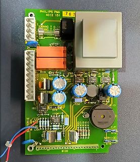
Bestückte Leiterplatte eines Philips Netzteils
T K121 R115 T93 I81 1102 60 180 182 +DC16 +DC16 C65 1103 C51 C46 30 I83 +DC16 D73 S113 C54 T91 183 L130 BATTERIE L131 R37 C53 R20 R7 R9 R5 S118 B120
in „Bauteilbestimmung - Trafo“ · Analoge Elektronik und Schaltungstechnik · · Platinenfotos
-
PDF
Handbuch_EMV_in_Geba_uden_DE_01_09_small.pdf
vorhanden sein. Die folgenden zwei Formeln zeigen die Korrelation zwischen der Kopplungs-Impedanz C L, der Anzahl Spulen N, der Induktion und der Schleifen-Fläche A. 15 N 2 ∗μ ∗μ ∗ A L = r 0 C = K ∗ L ∗L l L 1 2 K ist der Kopplungsfaktor und dieser beschreibt, wie stark die beiden Induktivitäten miteinander
in „Neubau LAN-Verkabelung welches Kabel, welche Switche“ · PC Hard- und Software ·
-
Datei
ncrt0.a30
------------------------------- ; ; when copy less 64K byte BZERO .macro TOP_ ,SECT_ mov.b #00H, R0L mov.l #TOP_, A1 mov.w #sizeof SECT_ , R3 sstr.b .endm ; BCOPY .macro FROM_,TO_,SECT_ mov.l #FROM_ ,A0 mov.l #TO_ ,A1 mov.w #sizeof SECT_ , R3 smovf.b .endm ; ; when copy over 64K byte ;BZEROL .macro
-
PDF
NSP-3630_schematic.pdf
1 2 3 4 5 6 TR2 DA1 UF4003 HDV 9V+ CA1 L6 3.3UH CA4 CA2 R1B 470K1/4W 4mHX2 222/500V 100UF 0.1 47UF 9V- 4mHX2 R4 C8 D2 UF4003 L1 C3 L2 SW1 BR1 200K 1/2W VCC V 3300PF 3 L3 3.3UH CA3 D 7 12A KBL805 C6 R2 C10A 221P C10 C11 C12 0.1 D S1 F C2 250VAC
in „[DC-Schaltnetzteil] Reichelt Manson HCS-3302 Erfahrungen?“ · Analoge Elektronik und Schaltungstechnik ·
